@VonSzarvas said:
I have an oven with 8 channel ADC and additionally 8 temperature probes setup for that sort of testing.
If there's some spin code that would run on the target device, either outputting serial data and/or relying on the external logging probes collecting data, then I could make time to run it.
I guess you'd want to see a table with:
timestamp
temperature (perhaps P2 surface, P2 rear and oven ambient)
pin toggling at sysclock (or /1000's of sysclock) to track variation over temperature
some sort of serial or DAC voltage data to demonstrate the memory is working right ?
Yes that would be appropriate. Ideally we would run it through temperature and frequency and see how much the required delay varies. At least for my driver timing I sort of want to run my delay test (which already figures out the range of delays needed to get the memory to read correctly) but do it also over temperature. It's fairly slow though to step through the entire frequency range from 50-350MHz (maybe taking ~15-30 mins or more to run) so it could take quite a long time to collect, unless the temperature is stepped in larger amounts (say 5C per step from 0-60C or something for a typical operational range).
I suppose you don't have a way to cool it though if it is an oven, so it's just room temp to a high temp, right?
To validate the memory itself is reliable over temperature is probably a different test to what I have for determining delay. You'd want to continually hammer it with random writes and reads looking for any bit errors. For that you need to know my driver is reliable first.
Ground-plane temperature under the Prop2 is my favourite spot. Other locations are extraneous imho.
If wanting to fully test this then going down to freezing would be another point to measure.
I'd be surprised if anything is learned with small increments but good to have the proof if you want. I'd go for just a few points altogether, say 0 °C, 25 °C, 50 °C and 75 °C. Freezer/chiller packs work well for controlling temp around 0 °C. Might have to settle for -5 or thereabouts.
Roger's delay scanner test is perfect for this. It clearly shows the borders and we can extrapolate a little for extra tolerance. That's all we need: The frequency scan report and a note of the board temperature added to the report. Four of those, one for each temperature point, should be job done.
Cooling is natural. At the moment we can log as temp rises and falls, with a set target point that holds to about +/- 2C.
The rise time is a gentle enough curve; I could slow it down by using a lower power setting on the heaters. Once we hit go I don't need to watch the thing- all the time will come in crunching the data later !
I'm with evanh in suggesting 2 or 3 set points to dwell on for a few minutes. That worked well last time, with too many intermediate steps taking far too long for an initial overview of capabilities.
I think we did room (approx 22), 50, 85, 100, 125 and 150 last time. I'd ditch the 150 and maybe 100 or 125. Depends on all the cap ratings... need to check first if they are all 125C rated. Hmm, probably not; too expensive.
@evanh said:
Ground-plane temperature under the Prop2 is my favourite spot. Other locations are extraneous imho.
If wanting to fully test this then going down to freezing would be another point to measure.
I'd be surprised if anything is learned with small increments but good to have the proof if you want. I'd go for just a few points altogether, say 0 °C, 25 °C, 50 °C and 75 °C. Freezer/chiller packs work well for controlling temp around 0 °C. Might have to settle for -5 or thereabouts.
Roger's delay scanner test is perfect for this. It clearly shows the borders and we can extrapolate a little for extra tolerance. That's all we need: The frequency scan report and a note of the board temperature added to the report. Four of those, one for each temperature point, should be job done.
Yeah or we could do 10C or 20C steps. Depends how fine grained we want to go.
Initially I had the idea to use the temperature in my driver to interpolate from a group of delay profiles (see the API below) but we don't know what the temperature is as there is no direct thermal sensor in the P2 so the tempK parameter is unused (and may never be used unless there's another indirect way to get the P2 temperature). I think the adaptive (closed loop) solution makes more sense though as it supports timing variation from P2 process and voltage as well as any external memory device variation, not just temperature.
setDelayFrequency(addr, freq, tempK)

Sets the frequency of operation and updates the input delay parameter for a given device's bank(s)
Uses the input timing/temperature profile for the device that operates at the address.

Arguments:
   addr - (any) address of device to setup input delay
   freq - current operating frequency in Hz
   tempK - (future use) temperature in Kelvin.  Pass 0 for now to ignore.

Returns: delay to use or negative error code
................................................................................................
}}
PUB setDelayFrequency(addr, freq, tempK) : r | bus, bank, delay
    bus := addrMap[addr >> 28]
    bank := (addr >> 24) & $f
    if bus +> LAST_INSTANCE
        return ERR_INVALID
    delay := lookupInputDelay(freq, profiles[bus * NUMBANKS + bank])
    return setDelay(addr, delay)
@VonSzarvas said:
Cooling is natural. At the moment we can log as temp rises and falls, with a set target point that holds to about +/- 2C.
The rise time is a gentle enough curve; I could slow it down by using a lower power setting on the heaters. Once we hit go I don't need to watch the thing- all the time will come in crunching the data later !
I'm with evanh in suggesting 2 or 3 set points to dwell on for a few minutes. That worked well last time, with too many intermediate steps taking far too long for an initial overview of capabilities.
I think we did room (approx 22), 50, 85, 100, 125 and 150 last time. I'd ditch the 150 and maybe 100 or 125. Depends on all the cap ratings... need to check first if they are all 125C rated. Hmm, probably not; too expensive.
Ok, I only read this after posting my last one. Yeah coarser temperatures make more sense then. The code would stop after all frequencies get tested (logging the results) and you could then adjust the temp and run it again when it hits the right temperature. If you capture the serial output during or afterwards my program should be mostly automatic and just need two frequency range arguments entered for each temperature before it resumes again. So not a lot of interaction if not many temperatures are run.
Oh wow, that looks excellent!
My current project is just about maxxed out on the 512KB, with a chunk of that being the GUI that I had to compromise on to make fit (128x96 8x8 16-color glyphs). This will be a great visual upgrade down the line!
One cog for video, and one cog for RAMs. Separate drivers. Some hubRAM for each too. RAMs on the Edge 32MB use a decent chunk of pins, most of the upper 32 are reserved, not all for RAMs though. Video is 5 pins (VGA pin count).
VGA uses 5 P2 pins and the 16 bit wide PSRAM in this memory configuration uses 18 P2 pins. You could in theory run a PSRAM memory bank with 6 pins but it would only have 1/4 of the bandwidth and not be able to do a lot of resolutions. I may still choose to do make a 4 bit PSRAM variant of this down the track as my P2 Voyager board has a single PSRAM chip fitted and it might just be able to drive an 800x480 LCD.
The PSRAM driver COG is full so it consumes about 4kB, same again for the video driver.
As far as HUB RAM use goes, for a pure external video frame buffer application, at a minimum the video driver needs two scan line sized buffers (~1920x2 bytes worst case for 1080p 8bpp) plus a display structure (56 bytes), a region structure (48 bytes), and a video timing structure (28 bytes). The PSRAM COG needs a startup data structure (32 bytes), memory bank information (128 bytes), cog qos (32 bytes) and the mailbox area (96 bytes). You could even reclaim the PSRAM and/or video driver COG space for the scan line buffers too, leaving a very minimal HUB footprint indeed (probably something under ~9kB).
Yeah the footprint is still quite small for the barest bones setup which is good. For the API I've been fighting's SPIN's inclusion of all driver code whether it is called or not. I'd really like to have a rich API that has lots of useful access functions but only bring in what is actually called. It's not a particularly fun battle. I also don't want to maintain lots of duplicated files with very minor differences between all the different memory types. Perhaps some method pointers can help me down the track split things cleanly but I don't want to slow down any time critical functions either...developing in SPIN is not really my forte (as yet), I'm probably better off in PASM. I miss the pre-processor and include files too much etc.
Just realized I've not updated the timing for PSRAM specifically for the P2 Edge in the last released driver code, will do that when I can get the time after Christmas. If it affects anyone who needs this working over frequency range in the meantime, they can run the delay test to find if their board is about the same as I'd measured in the top post. If it is then something like this delay profile should be reasonable for now.
In memory.spin2 use:
PSRamDelays long 6, 80_000000, 125_000000, 183_000000, 254_000000, 312_000000, 330_000000
and in psram.spin2 use:
delaytable long 6, 80_000000, 125_000000, 183_000000, 254_000000, 312_000000, 330_000000
Yippie, the SRAM driver works!
Even with long wires on a breadboard - RES_640x480, RES_800x600 and RES_1280x1024 looks great! (RES_1024x768 has noise)
Will do extensive testing next year :-)
This is the perfect XMAS gift... Thanks @rogloh !
@rogloh said:
I may still choose to do make a 4 bit PSRAM variant of this down the track as my P2 Voyager board has a single PSRAM chip fitted and it might just be able to drive an 800x480 LCD.
That would be a nice option, just one PSRAM for low res lcd & vga 640x480 stuff...
Also just using the memory driver and 6 pins for a (PSRAM64H) psram would be great if lots of cheap external ram is needed but not many free pins can be spared...
Perhaps, one can still have the option to use any single chip (from the four-set, as at the new Edge PSRAM board), simply by having a (perhaps) common scratchpad address area, where those "to-be-trashed" Writes can occur, safelly, anytime one needs to modify only any four-bit set (or eight, twelve, thereoff), out from the total sixteen available.
Sure, the total sum of "used timing" for those "one-up-to-three, out-of-four" operations need to match the whole timing allowance for the intended application, but, if it's entirelly possible, it'll open some neat opportunities (kind of a non-usual WMLONG-alternative).
Reading one or more four-bit-sets is simply a no-concern, at all, since it don't overwrites anything, and can be conducted safelly, even when the remaining bits are being overwriten, at their specific four-bit channels.
In short: this way, read/write ops can be intermixed, and occur concurrently, depending solelly on the driver code.
@aaaaaaaargh said:
Yippie, the SRAM driver works!
Even with long wires on a breadboard - RES_640x480, RES_800x600 and RES_1280x1024 looks great! (RES_1024x768 has noise)
Will do extensive testing next year :-)
This is the perfect XMAS gift... Thanks @rogloh !
No worries, glad it is useful. It is still beta and there might be issues because SRAM was far less tested compared to other memory types, but have a play and see what works and what doesn't. I might be able to fix whatever is broken.
@aaaaaaaargh said:
@rogloh said:
I may still choose to do make a 4 bit PSRAM variant of this down the track as my P2 Voyager board has a single PSRAM chip fitted and it might just be able to drive an 800x480 LCD.
That would be a nice option, just one PSRAM for low res lcd & vga 640x480 stuff...
Also just using the memory driver and 6 pins for a (PSRAM64H) psram would be great if lots of cheap external ram is needed but not many free pins can be spared...
Yes it is nicer on pins and could still be useful even with a lower bandwidth.
@Yanomani said:
Perhaps, one can still have the option to use any single chip (from the four-set, as at the new Edge PSRAM board), simply by having a (perhaps) common scratchpad address area, where those "to-be-trashed" Writes can occur, safelly, anytime one needs to modify only any four-bit set (or eight, twelve, thereoff), out from the total sixteen available.
Sure, the total sum of "used timing" for those "one-up-to-three, out-of-four" operations need to match the whole timing allowance for the intended application, but, if it's entirelly possible, it'll open some neat opportunities (kind of a non-usual WMLONG-alternative).
Reading one or more four-bit-sets is simply a no-concern, at all, since it don't overwrites anything, and can be conducted safelly, even when the remaining bits are being overwriten, at their specific four-bit channels.
In short: this way, read/write ops can be intermixed, and occur concurrently, depending solelly on the driver code.
Hope it helps
Henrique
Sounds like byte masking out of the four RAMs. I've already had some trouble fitting what I have all in, so I'm not sure I'll be going down that path any time soon. I do have read-modify-write capability at the bitmask level which is useful for graphics modes that need to update individual pixel data within the long for those colour modes where a pixel takes up less than a long (ie. most of them).
@Wuerfel_21 said:
Just snagged the product guide - is the RAM really only rated for 84 MHz in burst mode? That's one hell of an overclock we're doing, then?
My driver does not cross the page boundary at this speed. It closes out the transfer and opens a new one at the start of the next page. This is invisible to the caller. So the overclock is happening only for clock speeds over 133MHz (P2 @ 266MHz). The page size is 1kB but with 4 paralleled devices this is effectively a 4kB page size so the page crossing is not too frequent and would not affect performance very much when transferring large blocks of data.
Will be slightly obnoxious for the MD emulator though (weird performance differences based on how the code aligns to that 4K boundary). Though given that's mostly latency/overhead-sensitive, wonder if running sysclock/3 or sysclock/4 or smth but using linear mode would actually end up quicker. But who knows what the reliable overclock limit for linear mode is? sys/4 would be slightly under the rated 84MHz.
It should not be noticeable if you are prefetching blocks of instructions that are powers of two sized and already align on the boundaries (inherently). You could transfer at sysclk/4 (in your own code) if you are worried about this. E.g. run the P2 @ 320MHz and memory bus at 80MHz in your MD application. Although I just read that you can only cross the boundary once at this speed. The previous RAM we tested did not have this limitation from what I recall.
@rogloh said:
It should not be noticeable if you are prefetching blocks of instructions that are powers of two sized and already align on the boundaries (inherently). You could transfer at sysclk/4 (in your own code) if you are worried about this. E.g. run the P2 @ 320MHz and memory bus at 80MHz in your MD application. Although I just read that you can only cross the boundary once at this speed. The previous RAM we tested did not have this limitation from what I recall.
The prefetch blocks do not align on anything, they start at whatever address the branch target is and then go from then on until the next far branch. Reading them aligned would often end up reading a block, executing only the last one or two words and then moving on to the next one.
Though thinking about it, sys/4 would exactly be twice as slow for the actual transfer (the "low speed" read command sadly only applies to <=66 MHZ), but I'm thinking figuring out if a requested read crosses a 4K boundary and making the read routine be able to do two reads (i.e. preserving/advancing the relevant registers) seems like major pain. Like, 10+ instructions of pain.
Given the address and transfer length (in units of longs)...
wrfast bit31,hub_addr
mov tmp1,psram_addr
add tmp1,read_len
mov tmp0,psram_addr
bith tmp0,#0 addbits 11
add tmp0,#1 ' tmp0 has start of next page
cmpsub tmp1,tmp0 wcz ' IF C, tmp1 now has longs that cross over boundary
if_c sub read_len,tmp1
call #do_psram_read ' has to preseve flags and tmp0/tmp1
if_nc_or_z ret wcz
mov psram_addr,tmp0
mov read_len,tmp1
jmp #do_psram_read ' could be fall-through
Actually, that's not too terrible. Especially since the FIFO can just continue (so no need to multiply that transfer length by 4 and add it to the address).
Unrelatedly, after the transfer is done, is there any chance to read the final word from hub RAM before the
FIFO gets to write it? In that case there needs to be a blocking WRFAST afterwards (that can be in the callee, since only random reads need it - code and DMA reads always start at the beginning)
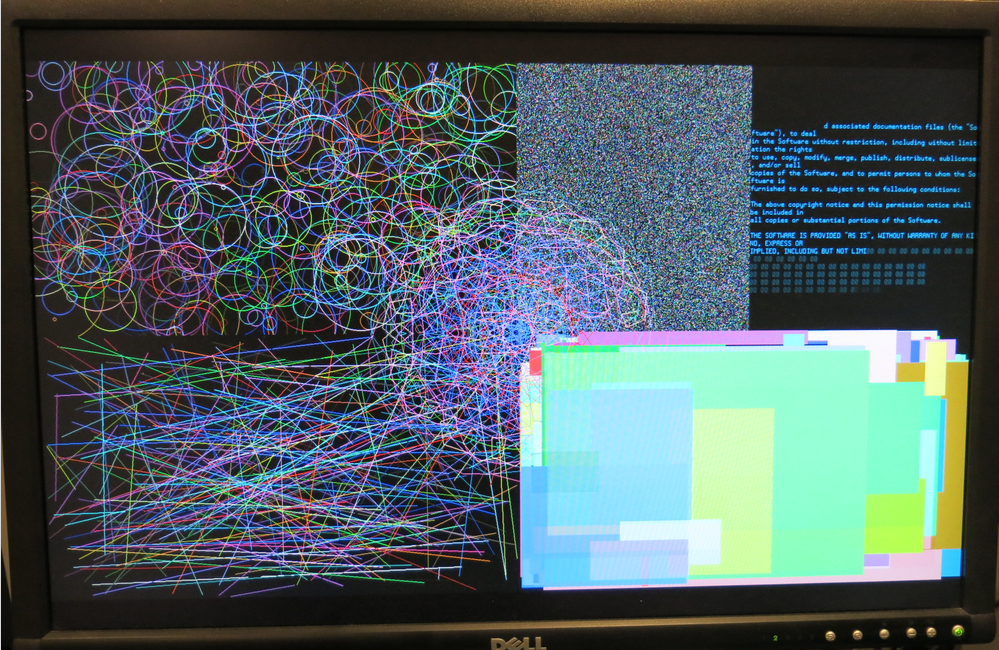
@rogloh said:
This is what you can do with it now in 1080p 8bpp.
By the way, the sample PSRAM graphics demo provided only uses individual pixel writes from SPIN2 to generate the text characters (its unoptimized code below was hacked up quickly) and the text render speed is affected accordingly. Even then it's actually still fairly usable.
In my own testing, I know there are much faster ways to generate text and write wider blocks of data which speeds things up a lot more. Like I already did for accelerating line drawing in 8/16/32bpp depths, I should probably look into whether extending built in graphics functions to output text makes sense. I'd just need a table pointer to the font and its size/width, the bpp and screen pitch and character index to be drawn (or a string pointer) and the fg/bg colours, and the memory driver could do the font reads and graphics writes for you automatically, deferring to any higher priority COGs after each scan line for example. This might be a handy way to speed it up even more.
Rendering text into a temporary hub RAM buffer and doing a graphics copy might still be faster, so I will need to test that too. You might want more control of line breaks and other special character handling so the acceleration would need to be fairly generic, perhaps just stopping, or wrapping/clipping at the text field rectangle extents for example.
PRI gfxDrawChar(ch, xstart, ystart, font, fontheight, fgcolour, bgcolour) | x, y, fontdata, addr, mask, transparent, stride
    stride:=LINEBUFSIZE
    addr := RAM + ystart*stride + xstart
    'only 8bpp implementation
    repeat y from 0 to fontheight-1
        fontdata:=byte[font][(y<<8) + (ch & $ff)]
        repeat x from 0 to 7
            if (fontdata & (1<<x))
                mem.fillbytes(addr, fgcolour, 1, 0)
            elseif fgcolour <> bgcolour ' not transparent
                mem.fillbytes(addr, bgcolour, 1, 0)
            addr++
        addr+=stride-8
@aaaaaaaargh said:
Yippie, the SRAM driver works!
Even with long wires on a breadboard - RES_640x480, RES_800x600 and RES_1280x1024 looks great! (RES_1024x768 has noise)
Try this alternate timing for RES_1024x768 to see it it helps you...the original ran the P2 at 325MHz which might be too fast for your setup. If that doesn't work you could also drop the 260000000 to 195000000 and set the 4<<8 parameter to 3<<8 instead as well to clock it even slower (no good for text regions, but may still be okay for graphics at 8bpp or less). But running the P2 at 260MHz gives you far better write performance.
xga_timing ' 1024x768@60Hz at 65*4 MHz YMMV
            long   0
            long   260000000
                   '_HSyncPolarity___FrontPorch__SyncWidth___BackPorch__Columns
                   '     1 bit         7 bits      8 bits      8 bits    8 bits
            long   (SYNC_NEG<<31) | ( 24<<24) | (136<<16) | (160<<8 ) |(1024/8)

                   '_VSyncPolarity___FrontPorch__SyncWidth___BackPorch__Visible
                   '     1 bit         8 bits      3 bits      9 bits   11 bits
            long   (SYNC_NEG<<31) | (  3<<23) | (  6<<20) | (29<<11) | 768
            long    4 << 8
            long    0
            long    0   ' reserved for CFRQ parameter
Here's a 8x faster text rendering implementation for my PSRAM demo above if you use flexspin (it also needs an 8 byte temporary array called textbuf added in a DAT section). There will certainly be other things that could be done to speed it up even more.
PRI gfxDrawChar(ch, xstart, ystart, font, fontheight, fgcolour, bgcolour) | hubaddr, y, fontdata, addr
    addr := RAM + ystart*LINEBUFSIZE + xstart
    hubaddr:=@textbuf
    'only 8bpp implementation
    repeat y from 0 to fontheight-1
      asm
        getbyte ptrb, ch,#0
        setbyte ptrb, y, #1
        add ptrb, font
        rdbyte fontdata, ptrb
        mov ptrb, hubaddr
        rep #3, #8
        rcr fontdata, #1 wc
        if_c wrbyte fgcolour, ptrb++
        if_nc wrbyte bgcolour, ptrb++
      endasm
      mem.write(hubaddr, addr, 8)
      addr+=LINEBUFSIZE


Comments
Yes that would be appropriate. Ideally we would run it through temperature and frequency and see how much the required delay varies. At least for my driver timing I sort of want to run my delay test (which already figures out the range of delays needed to get the memory to read correctly) but do it also over temperature. It's fairly slow though to step through the entire frequency range from 50-350MHz (maybe taking ~15-30 mins or more to run) so it could take quite a long time to collect, unless the temperature is stepped in larger amounts (say 5C per step from 0-60C or something for a typical operational range).
I suppose you don't have a way to cool it though if it is an oven, so it's just room temp to a high temp, right?
To validate the memory itself is reliable over temperature is probably a different test to what I have for determining delay. You'd want to continually hammer it with random writes and reads looking for any bit errors. For that you need to know my driver is reliable first.
Ground-plane temperature under the Prop2 is my favourite spot. Other locations are extraneous imho.
If wanting to fully test this then going down to freezing would be another point to measure.
I'd be surprised if anything is learned with small increments but good to have the proof if you want. I'd go for just a few points altogether, say 0 °C, 25 °C, 50 °C and 75 °C. Freezer/chiller packs work well for controlling temp around 0 °C. Might have to settle for -5 or thereabouts.
Roger's delay scanner test is perfect for this. It clearly shows the borders and we can extrapolate a little for extra tolerance. That's all we need: The frequency scan report and a note of the board temperature added to the report. Four of those, one for each temperature point, should be job done.
Cooling is natural. At the moment we can log as temp rises and falls, with a set target point that holds to about +/- 2C.
The rise time is a gentle enough curve; I could slow it down by using a lower power setting on the heaters. Once we hit go I don't need to watch the thing- all the time will come in crunching the data later !
I'm with evanh in suggesting 2 or 3 set points to dwell on for a few minutes. That worked well last time, with too many intermediate steps taking far too long for an initial overview of capabilities.
I think we did room (approx 22), 50, 85, 100, 125 and 150 last time. I'd ditch the 150 and maybe 100 or 125. Depends on all the cap ratings... need to check first if they are all 125C rated. Hmm, probably not; too expensive.
Yeah or we could do 10C or 20C steps. Depends how fine grained we want to go.
Initially I had the idea to use the temperature in my driver to interpolate from a group of delay profiles (see the API below) but we don't know what the temperature is as there is no direct thermal sensor in the P2 so the tempK parameter is unused (and may never be used unless there's another indirect way to get the P2 temperature). I think the adaptive (closed loop) solution makes more sense though as it supports timing variation from P2 process and voltage as well as any external memory device variation, not just temperature.
setDelayFrequency(addr, freq, tempK) Sets the frequency of operation and updates the input delay parameter for a given device's bank(s) Uses the input timing/temperature profile for the device that operates at the address. Arguments: addr - (any) address of device to setup input delay freq - current operating frequency in Hz tempK - (future use) temperature in Kelvin. Pass 0 for now to ignore. Returns: delay to use or negative error code ................................................................................................ }} PUB setDelayFrequency(addr, freq, tempK) : r | bus, bank, delay bus := addrMap[addr >> 28] bank := (addr >> 24) & $f if bus +> LAST_INSTANCE return ERR_INVALID delay := lookupInputDelay(freq, profiles[bus * NUMBANKS + bank]) return setDelay(addr, delay)Ok, I only read this after posting my last one. Yeah coarser temperatures make more sense then. The code would stop after all frequencies get tested (logging the results) and you could then adjust the temp and run it again when it hits the right temperature. If you capture the serial output during or afterwards my program should be mostly automatic and just need two frequency range arguments entered for each temperature before it resumes again. So not a lot of interaction if not many temperatures are run.
Oh wow, that looks excellent!
My current project is just about maxxed out on the 512KB, with a chunk of that being the GUI that I had to compromise on to make fit (128x96 8x8 16-color glyphs). This will be a great visual upgrade down the line!
Driver for PSRAM now available here (in first post):
https://forums.parallax.com/discussion/171176/memory-drivers-for-p2-psram-sram-hyperram-was-hyperram-driver-for-p2
This is what you can do with it now in 1080p 8bpp.
Very cool
I don't normally pay attention to video topics so, in summary, what P2 resources are required to achieve this (pins/memory/cogs)?
One cog for video, and one cog for RAMs. Separate drivers. Some hubRAM for each too. RAMs on the Edge 32MB use a decent chunk of pins, most of the upper 32 are reserved, not all for RAMs though. Video is 5 pins (VGA pin count).
Yes 2 driver COGs are needed.
VGA uses 5 P2 pins and the 16 bit wide PSRAM in this memory configuration uses 18 P2 pins. You could in theory run a PSRAM memory bank with 6 pins but it would only have 1/4 of the bandwidth and not be able to do a lot of resolutions. I may still choose to do make a 4 bit PSRAM variant of this down the track as my P2 Voyager board has a single PSRAM chip fitted and it might just be able to drive an 800x480 LCD.
The PSRAM driver COG is full so it consumes about 4kB, same again for the video driver.
As far as HUB RAM use goes, for a pure external video frame buffer application, at a minimum the video driver needs two scan line sized buffers (~1920x2 bytes worst case for 1080p 8bpp) plus a display structure (56 bytes), a region structure (48 bytes), and a video timing structure (28 bytes). The PSRAM COG needs a startup data structure (32 bytes), memory bank information (128 bytes), cog qos (32 bytes) and the mailbox area (96 bytes). You could even reclaim the PSRAM and/or video driver COG space for the scan line buffers too, leaving a very minimal HUB footprint indeed (probably something under ~9kB).
2 cogs and not much memory. Thats a lot lower footprint than i imagined.
The single PSram would be quite interesting too
Yeah the footprint is still quite small for the barest bones setup which is good. For the API I've been fighting's SPIN's inclusion of all driver code whether it is called or not. I'd really like to have a rich API that has lots of useful access functions but only bring in what is actually called. It's not a particularly fun battle. I also don't want to maintain lots of duplicated files with very minor differences between all the different memory types. Perhaps some method pointers can help me down the track split things cleanly but I don't want to slow down any time critical functions either...developing in SPIN is not really my forte (as yet), I'm probably better off in PASM. I miss the pre-processor and include files too much etc.
Just realized I've not updated the timing for PSRAM specifically for the P2 Edge in the last released driver code, will do that when I can get the time after Christmas. If it affects anyone who needs this working over frequency range in the meantime, they can run the delay test to find if their board is about the same as I'd measured in the top post. If it is then something like this delay profile should be reasonable for now.
In memory.spin2 use:
and in psram.spin2 use:
Yippie, the SRAM driver works!
Even with long wires on a breadboard - RES_640x480, RES_800x600 and RES_1280x1024 looks great! (RES_1024x768 has noise)
Will do extensive testing next year :-)
This is the perfect XMAS gift... Thanks @rogloh !
That would be a nice option, just one PSRAM for low res lcd & vga 640x480 stuff...
Also just using the memory driver and 6 pins for a (PSRAM64H) psram would be great if lots of cheap external ram is needed but not many free pins can be spared...
Perhaps, one can still have the option to use any single chip (from the four-set, as at the new Edge PSRAM board), simply by having a (perhaps) common scratchpad address area, where those "to-be-trashed" Writes can occur, safelly, anytime one needs to modify only any four-bit set (or eight, twelve, thereoff), out from the total sixteen available.
Sure, the total sum of "used timing" for those "one-up-to-three, out-of-four" operations need to match the whole timing allowance for the intended application, but, if it's entirelly possible, it'll open some neat opportunities (kind of a non-usual WMLONG-alternative).
Reading one or more four-bit-sets is simply a no-concern, at all, since it don't overwrites anything, and can be conducted safelly, even when the remaining bits are being overwriten, at their specific four-bit channels.
In short: this way, read/write ops can be intermixed, and occur concurrently, depending solelly on the driver code.
Hope it helps
Henrique
No worries, glad it is useful. It is still beta and there might be issues because SRAM was far less tested compared to other memory types, but have a play and see what works and what doesn't. I might be able to fix whatever is broken.
Yes it is nicer on pins and could still be useful even with a lower bandwidth.
Sounds like byte masking out of the four RAMs. I've already had some trouble fitting what I have all in, so I'm not sure I'll be going down that path any time soon. I do have read-modify-write capability at the bitmask level which is useful for graphics modes that need to update individual pixel data within the long for those colour modes where a pixel takes up less than a long (ie. most of them).
A few in stock today if anyone is waiting.
https://www.parallax.com/product/p2-edge-module-with-32mb-ram/
Selling out super fast- don't delay")
Just snagged the product guide - is the RAM really only rated for 84 MHz in burst mode? That's one hell of an overclock we're doing, then?
Yeah, but remember that's per 4-bit device on the 16-bit bus, with simultaneous access possible.
Seems like a good moment to share the current PSRAM datasheet : https://drive.google.com/drive/folders/11CobnTTaNjHhzz4Ru2xPjKjYpZRpsQJS
My driver does not cross the page boundary at this speed. It closes out the transfer and opens a new one at the start of the next page. This is invisible to the caller. So the overclock is happening only for clock speeds over 133MHz (P2 @ 266MHz). The page size is 1kB but with 4 paralleled devices this is effectively a 4kB page size so the page crossing is not too frequent and would not affect performance very much when transferring large blocks of data.
Will be slightly obnoxious for the MD emulator though (weird performance differences based on how the code aligns to that 4K boundary). Though given that's mostly latency/overhead-sensitive, wonder if running sysclock/3 or sysclock/4 or smth but using linear mode would actually end up quicker. But who knows what the reliable overclock limit for linear mode is? sys/4 would be slightly under the rated 84MHz.
It should not be noticeable if you are prefetching blocks of instructions that are powers of two sized and already align on the boundaries (inherently). You could transfer at sysclk/4 (in your own code) if you are worried about this. E.g. run the P2 @ 320MHz and memory bus at 80MHz in your MD application. Although I just read that you can only cross the boundary once at this speed. The previous RAM we tested did not have this limitation from what I recall.
The prefetch blocks do not align on anything, they start at whatever address the branch target is and then go from then on until the next far branch. Reading them aligned would often end up reading a block, executing only the last one or two words and then moving on to the next one.
Though thinking about it, sys/4 would exactly be twice as slow for the actual transfer (the "low speed" read command sadly only applies to <=66 MHZ), but I'm thinking figuring out if a requested read crosses a 4K boundary and making the read routine be able to do two reads (i.e. preserving/advancing the relevant registers) seems like major pain. Like, 10+ instructions of pain.
Given the address and transfer length (in units of longs)...
Actually, that's not too terrible. Especially since the FIFO can just continue (so no need to multiply that transfer length by 4 and add it to the address).
Unrelatedly, after the transfer is done, is there any chance to read the final word from hub RAM before the
FIFO gets to write it? In that case there needs to be a blocking WRFAST afterwards (that can be in the callee, since only random reads need it - code and DMA reads always start at the beginning)
No delay here - It'll be waiting for me when I get home ... I hope.")
By the way, the sample PSRAM graphics demo provided only uses individual pixel writes from SPIN2 to generate the text characters (its unoptimized code below was hacked up quickly) and the text render speed is affected accordingly. Even then it's actually still fairly usable.
In my own testing, I know there are much faster ways to generate text and write wider blocks of data which speeds things up a lot more. Like I already did for accelerating line drawing in 8/16/32bpp depths, I should probably look into whether extending built in graphics functions to output text makes sense. I'd just need a table pointer to the font and its size/width, the bpp and screen pitch and character index to be drawn (or a string pointer) and the fg/bg colours, and the memory driver could do the font reads and graphics writes for you automatically, deferring to any higher priority COGs after each scan line for example. This might be a handy way to speed it up even more.
Rendering text into a temporary hub RAM buffer and doing a graphics copy might still be faster, so I will need to test that too. You might want more control of line breaks and other special character handling so the acceleration would need to be fairly generic, perhaps just stopping, or wrapping/clipping at the text field rectangle extents for example.
PRI gfxDrawChar(ch, xstart, ystart, font, fontheight, fgcolour, bgcolour) | x, y, fontdata, addr, mask, transparent, stride stride:=LINEBUFSIZE addr := RAM + ystart*stride + xstart 'only 8bpp implementation repeat y from 0 to fontheight-1 fontdata:=byte[font][(y<<8) + (ch & $ff)] repeat x from 0 to 7 if (fontdata & (1<<x)) mem.fillbytes(addr, fgcolour, 1, 0) elseif fgcolour <> bgcolour ' not transparent mem.fillbytes(addr, bgcolour, 1, 0) addr++ addr+=stride-8Try this alternate timing for RES_1024x768 to see it it helps you...the original ran the P2 at 325MHz which might be too fast for your setup. If that doesn't work you could also drop the 260000000 to 195000000 and set the 4<<8 parameter to 3<<8 instead as well to clock it even slower (no good for text regions, but may still be okay for graphics at 8bpp or less). But running the P2 at 260MHz gives you far better write performance.
xga_timing ' 1024x768@60Hz at 65*4 MHz YMMV long 0 long 260000000 '_HSyncPolarity___FrontPorch__SyncWidth___BackPorch__Columns ' 1 bit 7 bits 8 bits 8 bits 8 bits long (SYNC_NEG<<31) | ( 24<<24) | (136<<16) | (160<<8 ) |(1024/8) '_VSyncPolarity___FrontPorch__SyncWidth___BackPorch__Visible ' 1 bit 8 bits 3 bits 9 bits 11 bits long (SYNC_NEG<<31) | ( 3<<23) | ( 6<<20) | (29<<11) | 768 long 4 << 8 long 0 long 0 ' reserved for CFRQ parameterHere's a 8x faster text rendering implementation for my PSRAM demo above if you use flexspin (it also needs an 8 byte temporary array called textbuf added in a DAT section). There will certainly be other things that could be done to speed it up even more.
PRI gfxDrawChar(ch, xstart, ystart, font, fontheight, fgcolour, bgcolour) | hubaddr, y, fontdata, addr addr := RAM + ystart*LINEBUFSIZE + xstart hubaddr:=@textbuf 'only 8bpp implementation repeat y from 0 to fontheight-1 asm getbyte ptrb, ch,#0 setbyte ptrb, y, #1 add ptrb, font rdbyte fontdata, ptrb mov ptrb, hubaddr rep #3, #8 rcr fontdata, #1 wc if_c wrbyte fgcolour, ptrb++ if_nc wrbyte bgcolour, ptrb++ endasm mem.write(hubaddr, addr, 8) addr+=LINEBUFSIZE