

P1 Frequency Synthesizer demo v1.1
 pic18f2550
Posts: 400
pic18f2550
Posts: 400
Hello,
I want to feed my P1 from a 10Mhz oscillator and not use a PLL. (CLKFREQ=10Mhz)
Therefore the question arises in which frequency range I can cover with the code.
10Mhz / (PLLDIV * FRQA) = Fout
Furthermore I am looking for a formula how I can calculate the actual frequency from the calculated values (find rounding errors when calculating the values).
Thanks.
Comments
If you do not use PLL, I'm not sure where PLLDIV comes from ?
The Counters docs has
The general formula for the frequency in the NCO mode is
fHz= FRQA * SystemFrequency / 2^32
The above equation works for values of FRQA between 0 and $8000_0000; for values greater than $8000_0000 the output frequency decreases according to Figure 5.
For values of FRQA which are not a power of 2, there will be jitter present on the output signal since the most significant bit of PHSA will toggle at an inconstant rate.
In your cases SysCLK is 10.000MHz and the edge jitter will be 100ns
As an example, if you dial up the nearest to 10kHz, you actually get a long term average of
4294967 * 10M/2^32 = 9999.9993108Hz ( an averaged offset error of ~689 micro Hz )
but the jitter means that is actually the numerical average of two possible real or hardware frequencies
10M/1000 = 10k or 100.00us (mostly)
10M/1001 = 9990.00999 or 100.10us (rarely) *
If you are doing a frequency synthesizer demo, you might want to add a Reciprocal Frequency Counter to show the average frequency over (say) 1 second
Addit: * How often is 'rarely' ?
if you can inject a 10Hz offset to average ~689uHz that's once every ~14510 cycles, which we can check in the time-domain like this
(14510 * 2^32/(4294967 * 10M)) - (14509 * 100u+100.10u) = -1.629e-13
A counter with a gate time of 14510 cycles or 1.4510sec will display a stable 9999.9993108Hz, other gate times will display values that average to that.
If I understand the NCO mode correctly, 429.496.730 × 10.000.000 Hz ÷ 4.294.967.296 = 1.000.000,0009313 Mhz should result.
Yes, that's the correct long term average, but the NCO HW generates 10M/10 or rarely, one cycle of 10M/9, to reach that average.
I somehow lack the idea of how the NCO works internally with counters, etc. works.
Maybe a schematic would help me.
In the documentation I have only found the PLL variant.
https://www.parallax.com/package/an001-propeller-p8x32a-counters/
The CTR PLL comes only after the NCO, so it has limits on what it can do and a limited dynamic range :
A PLL is designed to work over a range of frequencies. The range for the input clock on the PLL located within each counter is 4 to 8MHz, which results in an output range of 64 to 128 MHz. Frequencies as low as 500 kHz can be output to APIN given the range of output divisions available from the PLL. Therefore, any frequency from 500 kHz to 128 MHz can be generated using the PLL counter modes. PLL counter modes can be used to generate Radio Frequencies (RF) and can help reduce jitter in a non-power of 2 FRQA value.
The P2 PLL is much more powerful, but the P2 has only one PLL for SysCLK
In NCO mode, a 32-bit number (freqx) is added to a 32-bit phase register (phsx) on every clock cycle. The output to the pin assigned to the counter reflects the value of the phase register's bit 31. If a second pin is assigned to the counter, it's output will be the opposite of bit 31.
-Phil
The Counter-PLL is an optional post-NCO block, with MHz limits, within each counter block. The SysCLK PLL is separate.
What frequency ranges are you trying to generate, to what precision ?
The PLLDIV parameter only applies to 3 of the 32 counter modes. One of those modes (PLL internal (video mode)) feeds the video generator, and the other two (PLL single-ended and PLL differential) connect the output of the PLL to either one or two output pins. The PLLDIV parameter has no effect in other 29 modes.
The two NCO modes (NCO single-ended and NCO differential) produce a square wave output pin. I like to look at the 32 bit phase accumulator, PHSA, as a clock face with 2^32 marks around the edge and with a pointer that advances an amount FRQA at each tick of the system clock, at 1/clkfreq second intervals. That is, FRQA is added to PHSA every 12.5ns when clkfreq=80MHz. The output pin is connected to bit 31 of the PHSA. So bit 31 is low when PHSA is less than 2^31 and high for the second half of the cycle.
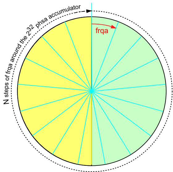
The math comes out as follows:
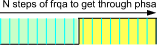
It takes N steps to get around the full circle, so
Each of those N steps takes time 1/clkfreq, so the total time to get around the circle is
That is the time for one cycle of low and high at the output pin.
That period repeats over and over as the process continues, so we have the output frequency at the pin,
frequency = clkfreq / N
             = clkfreq / (2^32 /FRQA)
             = clkfreq * FRQA /2^32.
You can rearrange that to find the FRQA necessary for a given frequency. If you need to calculate that in real time, or from a menu given desired frequency, there are binary division algorithms to crank it out.
As jmg mentioned, except for powers of two the math does not come out even There is a remainder from the division N=2^32/FRQA, and that leads to occasional jumps to N-1 or N+1 steps in a cycle: jitter. When FRQA is small, the output frequency is low, and the jitter is usually less significant compared to what happens at a high output frequency. When FRQA = 1, the output period is 2^32 * (1/clkfreq) = 53.69 seconds (when clkfreq=80MHz). However, you have to be satisfied with rough approximations, because when FRQA=2 and FRQA=3, the output period drops to 26.84 seconds and 17.9 seconds respectively. On the high end you have FRQA=2^31, for an output of 40MHz. You might think you could get very fine control of frequency up there, but the jitter cycles can be quite long. The jitter comes in long cycles that are related to the continued fraction expansion of 2^32 / N. The counters are most useful at Hz through hundreds of kHz range frequencies.
OK, I have understood that now.
This is the same principle as creating a sine with P2, only that here not the value but bit 31 is used.
When generating the signal, there are two counter values that generate jitter.
The 50% and 100% transition of 32-bit phase register (phsx).
If you are looking for a frequency with little jitter, it should be divisible by 2 and the result should still be an even number.
The P1 is powered by a FE5680A with 10Mhz.
If you have a high performance clock, you could look to add a simple /2 stage to get that 10MHz to a 5MHz within-spec value that the P1 SysCLK PLL can turn into 80MHz.
That has the same precision, and your jitter effects are 1/8 of 10MHz
I had the same thought.
The problem is that the internal PLL reacts sensitively to voltage fluctuations, which again becomes noticeable in a frequency modulation.
Since I am also calculating the frequency error, I also know what correction value I have to apply to the rubidium via the interface.
The P1 extends the frequency range that my FE5680A does not allow.
I've not seen jitter numbers for the P1 SysCLK PLL, but I'd expect them to be sub-ns and PSU care could improve the PSRR issues ?
There are useful general MCU PLL comments in this thread :
https://www.eevblog.com/forum/microcontrollers/timing-stability-of-mcu-plls/
That reports 'clean-logic' can reach 40ps and 'MCU logic' is usually 300~400-ps, as one comment says this :
Ok anything under 600ps is doable.
Thank you.
PLL jitter is highly dependent upon the value in FRQx. The more binary zeroes after the first non-zero bit, the better.
-Phil
There is another post at
https://www.eevblog.com/forum/microcontrollers/timing-stability-of-mcu-plls/
Looking at the TDC7200 he mentions, that auto-calibrates the internal fractional ns captures from an external clock, and it gives < 50ps deviation for 4~16MHz CAL source.
That means your FE5680A with 10MHz could clock that directly, and you could scale the stop pulse, to measure P1 PLL jitter over varying time windows up to the TDC7200 limit of 8ms
You could help things along, with a low noise high PSRR LDO. Parts like the OnSemi
NCV8163ASN330T1G 250 mA, Ultra-Low Noise, and High PSRR LDO, Regulator for RF and Analog Circuits
look like a good pairing.
The TDC7200 is suitable for time-of-flight measurements but not for generating different frequencies.
Yes, I was meaning to use that as a low cost means to measure the P1 SysCLK PLL jitter, the P1 still generates your frequencies.
I agree with Phil about counting zeros to the right of the first 1 in the binary representation of the FRQA tuning factor. That is the same thing as saying that there are a lot of 2s in the prime factorization, and those 2s cancel out when considering the ratio 2^32 / FRQA. In general, if there are no factors of 2, the total NCO cycle will be up to 53+ seconds (80MHz clkfreq). But with factors of 2, the maximum cycle length is reduced correspondingly. Let's say the ratio can be reduced to 2^16 / (FRQAcoprime), the maximum cycle length reduces to a fraction of a millisecond with the 80MHz clkfreq.
Add a PLL mode, driven by the NCO, I wonder. I don't recall what Chip said about the response time of the PLL ring oscillator, fast or slow in absolute terms?