

P2 DIP100 "Centipede"
 Fred777
Posts: 19
Fred777
Posts: 19
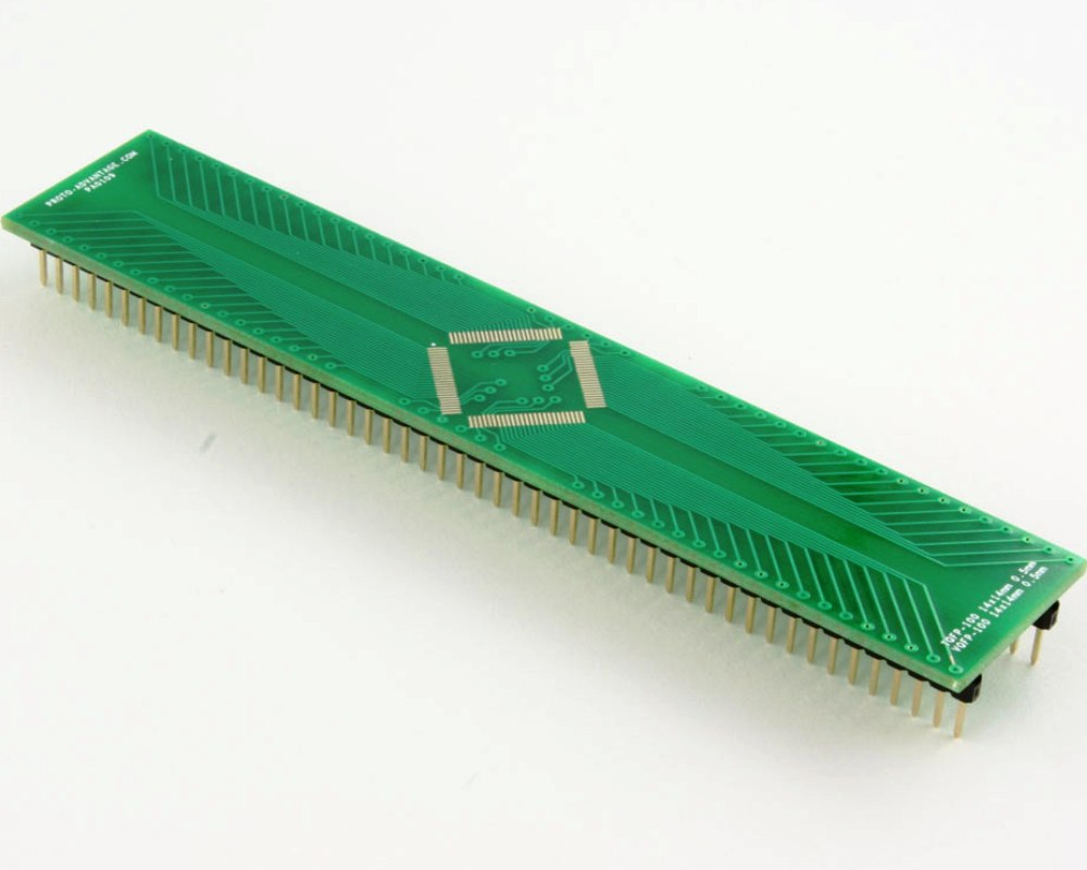
Hello all, I have an usused TQFP100 to DIP Adapter and would like to try to put a P2 onto that.
What are you thinking? Good idea or not? Problems? Tips? Maximum clock frequency to expect?
All comments are welcome.
Comments
Decoupling is going to be a serious challenge, and connecting to the GND tab under P2 an even bigger challenge.
I'm never going to say impossible, so maybe dead-bug and bent leads, with some hours manhattan wiring, could see a P2 with a pulse ?
Is that GND Tab really needed?
Unless you are going to end up with something as ugly as my ugly P1 board pictured in the post #33, I wouldn't bother. And that was only 44 pins and no GND tab underneath. Not worth the trouble, imho but...it would be very interesting to see what you can achieve if determined enough to do it.
Yes. If it wasn't @jmg wouldn't mention it")
Can you find another pin labeled GND ?")
Aaah, now I see what you mean, hadn't though of that at all, how would that normally be fixed to a pcb?
I'd like to see this work!
There's a test pin that is connected to ground right?
I'd drill a hole in the middle and solder a wire from the back of the P2 to the test pin and then connect to ground.
Will need some capacitors for sure.
I see a problem with the center where the ground plane should be, you have twelve pins wired to transistion holes in the center area. Those twelve would touch the ground pad in back of the P2. And Xtal would be further away.
@Rayman , you're a devil") !
!
The hole would be my approach as well. I'd use also some copper foil but...I'm not doing this.
I'd like to see that work too and I'm sure I could make it work myself but it would be a lousy job and frankly good for almost nothing. It would be extremely difficult to run the P2 at a reasonable clock frequency because there is no way to transfer the heat away from the P2 effectively with this board. Not to mention the lengths of these parallel traces introducing additional capacitances. However, if you limit the speed and chose the pins wisely it could work for some applications. But it is such a waste to use the P2 this way and a hell lot of effort.
@Fred777 , if you feel you must do it, go for it ! Otherwise stay away from that idea. You've been warned. Now the choice is yours.") . Good luck.
. Good luck.
And do not forget to post the progress reports here as you go, if you decide to take that path
To solve both those problems I would dead-bug it, bend the signal pins down, and the supply pins up, and mount decoupling caps almost straight onto the P2 thermal GND pad")
Xtal pins would be straight up to a hot-glue xtal, also dead bug on the GND tab - Manhattan wiring.
A few of the 100 pins could be GND repurposed, to help with pin path signal integrity, which will be poor overall.
Maybe 2 pins for 1v8, a Power in and a kelvin feedback to allow for amps across long thin traces.
Many hours of work, but would make a great photo
This looks like a complete waste of time, perfect in my view. A nice project for those dark winter evenings. The hole drilling and soldering the ground plane thing sounds like a plan.
I'll keep you updated about Project "P2 Centipede". First I'll have to get my hands on a P2...
Dead bug might be a good approach
The Centipede name is taken")
I have been working on a same-named project for the past year, although the similarities finish with the name...
I was going to comment on how to hack it on. But the more I think about it the more I think its simply not worth even considering. Make a custom board with proper decoupling capacitors. Actually, if I were to do it, I would at least consider putting the device on the underside of the board and putting a round through hole under there a little smaller than the width of the plastic package. Then solder a copper plug into it that makes the ground connection and allows you to mount a nice heat sink.