

Bs1 with a sensitive to static and noise display
 Luis_P
Posts: 246
Luis_P
Posts: 246
Hello! I built a project with seven BS1 microcontrollers controlling many 7-segment displays (SparkFun).
When I turn ON power on the BS1 microcontrollers (5V, 6A) some of the displays can get corrupted and I had to factory reset them all the time. It seems when I power the BS1 something bad is been sent out (TX output) to the display, noise or whatever is causing the display to go crazy. I've installed a power switch now to turn ON the displays 1 minute after I power the BS1 board. So far good but no the best approach.
My BS1 code does not send anything to the display until a button has been pressed.
Is anything else I can do to either protect the displays from this issue? 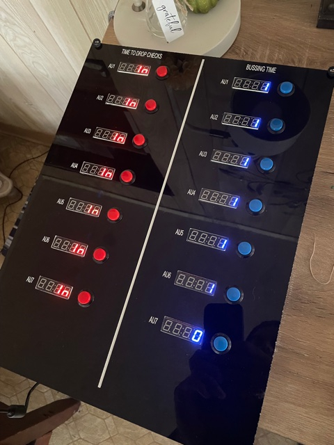
Displays:
https://www.sparkfun.com/products/11441
Part of my code:
SYMBOL A = W0
SYMBOL Baud = T2400
SYMBOL ProjPin = PIN0
PAUSE 5000 'wait for Bs1 to initialize properly
Main:
CheckSignal:
IF ProjPin=1 THEN Start ' Projector Relay signal
GOTO CheckSignal
Start:
A = 0
SEROUT 1, Baud, ($76, %00000000, $7B, %00000000, $7C, %00000000, $7D, %00000000, $7E, %01101101) ' 5
Comments
It looks like your start button and serial output are on the same pin (1).
Suggestions:
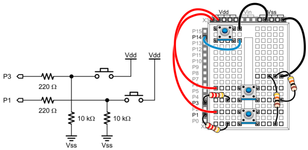
1. Put a pull-up on the serial pin to set that line into the idle state as soon as the BS1 has power
2. Debounce you button input to prevent false starts. There should be a pull-down on the input pin
10K is fine for the pull-up and pull-down
I'm nutty about program formatting -- here's how I would do your project.
' ========================================================================= ' ' File...... ' Purpose... ' Author.... ' E-mail.... ' Started... ' Updated... ' ' {$STAMP BS1} ' {$PBASIC 1.0} ' ' ========================================================================= ' -----[ Program Description ]--------------------------------------------- ' -----[ Revision History ]------------------------------------------------ ' -----[ I/O Definitions ]------------------------------------------------- SYMBOL SOut = 7 ' serial to display SYMBOL Trigger = PIN6 ' -----[ Constants ]------------------------------------------------------- SYMBOL Baud = T2400 SYMBOL IsOn = 1 ' for active-high in/out SYMBOL IsOff = 0 ' -----[ Variables ]------------------------------------------------------- SYMBOL timer = B2 ' -----[ Initialization ]-------------------------------------------------- Reset: PINS = %10000000 ' P7 is high to start DIRS = %10000000 ' P7 is output timer = 0 ' reset timer ' -----[ Program Code ]---------------------------------------------------- Main: PAUSE 5 ' loop pad timer = timer + 5 * Trigger ' update timer IF timer < 50 THEN Main ' wait for 50ms input Transmit: SEROUT SOut, Baud, ($76, %00000000, $7B, %00000000, $7C, %00000000) SEROUT SOut, Baud, ($7D, %00000000, $7E, %01101101) Hold_Off: PAUSE 5000 ' no new start for 5s GOTO Main ' back to top ' -----[ Subroutines ]----------------------------------------------------- ' ------------------------------------------------------------------------- ' -----[ User Data ]-------------------------------------------------------Hey JonnyMac! .
.
Sorry the pin for start button and serial output are not the same. I just made a typo mistake when posting my question
You mentioned to Put a pull-up on the serial pin. Like this?
...............................10K.................................
BS1 TXpin. --------/\/\/------ GND
BS1 TXpin. ---------------------RX Display
By the way my button has a pulldown already. How do I do a pullup resistor connection on the serial output?
Thanks
A resistor to ground is a pull-down. The resistor on the RX display line should be pulled up to Vdd.
-Phil
Hi Phil Thanks for your help. Please se my diagram, that's the way should be? The RX pin on the display has a 10K resistor to VDD ?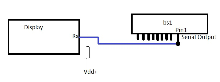
What this means?
Reset:
PINS = %10000000 ' P7 is output
DIRS = %10000000 ' P7 is high to start
How that works? what is it for?
Yes.
-Phil
This section of code presets all the IO pins. Since the serial line (P7 in my code) should be high as soon as possible so you don't get false data to the display, this puts that line in the idle state. When SEROUT runs it will leave the pin high as that is the idle state of True mode serial. There are other ways to do this; I prefer this style because it assumes nothing and lets us see how the pins will be initialized
Since the BS1 presets all pins to inputs, you could do this:
What's important is to get the serial line high ASAP. Using the pull-up makes this happen automatically -- though it doesn't hurt to do it code as well.
How about:
OUTPUT PIN7
Is that necessary? I read the manual and says I should tell the BS1 what pins are an output to use serout.
No.
That will set P0 or P1 to output mode, without setting the state, so it will probably be low. This is a subtle thing that often gets newcomers. When you use PIN7 you're asking for the state of P7. If you want to make P7 high without affecting anything else, do this:
That said, you should name your pins with the SYMBOL directive (as I did above) so that your code makes better sense to others. Naming pins is a good habit to get into. I know the BS1 only has 8 off them, but I'm asking you to trust me on this.
Yes, I know. That said, the BS1 won't put the pin into output state until SEROUT is used -- this means that pin would be in an unknown state (which could cause problems) until you press a button. One goal of any design is to ensure that any output is in a known state.
I've been coding the BS1 since 1994 and have written 100s of programs, many of them for the BS1-based Prop-1 controller (from EFX-TEK, a company I used to design circuits for) that is popular with Halloween and Christmas decorators, and even used in major theme parks like Disneyland. If you go through the Haunted Mansion and Disneyland when the "Nightmare Before Christmas" decorations are up, many of the little extra decorations are controlled by the BS1. All this is to say is that you can trust my guidance on the BS1; I will not steer you wrong.
JonnyMac please please look at my final code. Im using 5 pins total 2 are output and 3 are inputs. This is an automation for a Dine in Movie Theater by the way:
P0= PROJECTOR SIGNAL INPUT
'P1= SERVER DISPLAY OUTPUT
'P2= SERVER BUTTON INPUT
'P3= BUSSER DISPLAY OUTPUT
'P4= BUSSER BUTTON INPUT
SYMBOL A = W0
SYMBOL Baud = T2400
SYMBOL Trigger = PIN0
SYMBOL SOut1 = 1
SYMBOL SOut2 = 3
HIGH SOut1
HIGH SOut2
‘ these lines removed per JonnyMac suggestion
‘OUTPUT SOut1
‘OUTPUT SOut2
Main:
A = 0
CheckStatus:
PAUSE 5 ' loop pad
A = A + 5 * Trigger ' update timer
IF A < 50 THEN CheckStatus ' wait for 50ms input
SEROUT SOut1, Baud, ($7B, %00000000, $7C, %00000000, $7D, %00000000, $7E, %01101101) ' 5
By the way I solder a 10K resistor on the RX display to VDD.
You don’t have idea how much I appreciate your help jonnyMac!!!!
Luis
Luis,
I like to be jokey with a point -- a common phrase is use with clients is, "The root word of specification is specific!"
I am happy to help you with your code. What I don't need is your old code. What I do need is a description (in English, not code) of what is supposed to happen. You should include:
1) Number of inputs and type (e.g., button)
2) Number of outputs and behavior (simple high or low, or signal like SEROUT)
3) Is anything special suppose to happen on start up (e.g., with a display)
You have this list in your code:
Are these all of the IOs for the project? Are you wanting to look at multiple inputs (3) and control multiple (2) outputs? Be clear and complete. Piecemealing when you ask for help can lead to frustrations for those trying to help you. If we know the WHOLE story up front, that will drive the design of code. And... are you willing to change IO assignments? It's okay if you're not, but I think the code is neater and cleaner when IOs are assigned in an organized manner.
JonnyMac. Thanks again for your help. Understanding what we are going to use this for is kind of hard but I will try to explain.
In a dine in Movie Theater we have to go at the end of the movie and drop customers checks (receipts) and then bussers needs to go and clean. We have 7 Auditoriums. Each movie projector have relays (normally open) that we can use for automations. When the movie start showing the trailers the projector will close the relay. Pin 0 on my BS1 will detect (pull down resistor) and send commands to one of the displays (PIN 1) showing number 5 indicating we have 5 minutes to drop checks. After 5 minutes another display will show number 0 (PIN 3) and will count up to 10 so bussers have an idea when to go clean. The other 2 pins (PIN 2 and PIN 4) are buttons for us to press to clear the display when we completed the task. I know is hard to understand but works for us! Im using only 5 pins per each BS1 (total 7).
Each BS1 uses pin 0 waiting for the projector to close the relay. Pin 1 is the display showing time servers have to go and drop checks. Pin 2 is a button to clear the server timer display. Pin 3 is the display showing the time for the bussers to go and clean and finally Pin 4 is a button to clear the bussers display.
Let me see if I understand.
-- P0 (from relay) starts 5-minute countdown on the checks display?
-- After the 5-minute countdown that display (checks) is cleared?
-- The bussing display counts from 1 to 10? What is the delay between digits? Also 1 minute?
After the 5 min countdown the display shows “Out” then the bussing display starts at cero. Yes 1 min delay.
I still have problems with some display loosing the baud rate when power up and I have to do a factory reset on them. Either the display are defective or something is causing the displays to go nuts.
Is everything sequential? Do you have to clear "Out" before you can start the bussing timer?
No I don’t have to clear “out” everything is sequential. But after 20 min count the displays clear and shows a dot on the last digit then all start over again. Do you think because I have all displays hook up together for power is that an issue?
I don't know. One of the most difficult tasks of helping someone on the forums is really understanding what they're after. During my breaks this afternoon, I knocked together this code. It may not be exactly what you're looking for, but possibly close enough to modify for your needs.
' ========================================================================= ' ' File...... theatre_control.bs1 ' Purpose... ' Author.... Jon McPhalen ' E-mail.... ' Started... ' Updated... 03 NOV 2021 ' ' {$STAMP BS1} ' {$PBASIC 1.0} ' ' ========================================================================= ' -----[ Program Description ]--------------------------------------------- ' -----[ Revision History ]------------------------------------------------ ' -----[ I/O Definitions ]------------------------------------------------- SYMBOL Clr_Bussing = PIN4 ' 10K pull-down SYMBOL Bussing = 3 ' 10K pull-up SYMBOL Clr_Serving = PIN2 ' 10K pull-down SYMBOL Serving = 1 ' 10K pull-up SYMBOL Proj_Relay = PIN0 ' 10K pull-down ' -----[ Constants ]------------------------------------------------------- SYMBOL BAUD = T2400 SYMBOL IS_ON = 1 ' for active-high in/out SYMBOL IS_OFF = 0 ' digit maps %0gfedcba ' SYMBOL DIG_0 = %00111111 SYMBOL DIG_1 = %00000110 SYMBOL DIG_2 = %01011011 SYMBOL DIG_3 = %01001111 SYMBOL DIG_4 = %01100110 SYMBOL DIG_5 = %01101101 SYMBOL DIG_6 = %01111101 SYMBOL DIG_7 = %00000111 SYMBOL DIG_8 = %01111111 SYMBOL DIG_9 = %01100111 SYMBOL LTR_u = %00011100 SYMBOL LTR_t = %01111000 ' -----[ Variables ]------------------------------------------------------- SYMBOL display = B2 ' serial pin for display SYMBOL timer = B3 ' for displays SYMBOL cols01 = W4 SYMBOL col0 = B8 SYMBOL col1 = B9 SYMBOL cols23 = W5 SYMBOL col2 = B10 SYMBOL col3 = B11 ' Warning: Do not use B12, B13, or W6 ' -- used for subroutine stack ' -----[ Initialization ]-------------------------------------------------- Reset: PINS = %00001010 ' set serial pins to idle DIRS = %00001010 cols01 = 0 ' all segments off cols23 = 0 FOR display = Serving TO Bussing GOSUB Update_Display PAUSE 10 NEXT ' -----[ Program Code ]---------------------------------------------------- Main: timer = 0 Wait_For_Serving: PAUSE 5 timer = timer + 5 * Proj_Relay IF timer < 50 THEN Wait_For_Serving Serving_Timer: display = Serving FOR timer = 5 TO 1 STEP -1 READ timer, col0 ' convert to digit map GOSUB Update_Display PAUSE 60000 ' wait 1 minute NEXT col1 = DIG_0 ' display [ Out] col2 = LTR_u col3 = LTR_t GOSUB Update_Display ' timer = 0 ' Wait_To_Clear_Serving: ' PAUSE 5 ' timer = timer + 5 * Clr_Serving ' IF timer < 50 THEN Wait_To_Clear_Serving cols01 = 0 ' clear server display cols23 = 0 GOSUB Update_Display Bussing_Timer: ' count 0 to 9 display = Bussing FOR timer = 1 TO 9 READ timer, col3 GOSUB Update_Display PAUSE 60000 ' wait 1 minute NEXT READ 1, col2 ' stop at 10 READ 0, col3 GOSUB Update_Display ' Wait_To_Clear_Bussing: ' PAUSE 5 ' timer = timer + 5 * Clr_Bussing ' IF timer < 50 THEN Wait_To_Clear_Bussing GOTO Reset ' -----[ Subroutines ]----------------------------------------------------- ' Set display to pin for SEROUT Update_Display: SEROUT display, BAUD, ($7B, col0, $7C, col1, $7D, col2, $7E, col3) RETURN ' -----[ User Data ]------------------------------------------------------- Digit_Maps: EEPROM(DIG_0) EEPROM(DIG_1) EEPROM(DIG_2) EEPROM(DIG_3) EEPROM(DIG_4) EEPROM(DIG_5) EEPROM(DIG_6) EEPROM(DIG_7) EEPROM(DIG_8) EEPROM(DIG_9)JonnyMac Thank you very much! for this. I test the code and for some reason PIN2 is always HIGH.
I test the button with other code and works fine but when I run yours the state is always 1 (High) Why is that? the other PINS works fine. Only PIN2.
Luis
I don't know why that is. As you can see in the reset section, that pin is defined as an input (PIN2 is 3rd from right).
Did you modify this section? I looked through the listing and there is no use of HIGH anywhere; the only time PIN2 (aliased as Clr_Bussing) is used is in a switch debounce routine.
This is not my preferred style, but you could change reset to look like this to prevent accidents with bit alignment in the PINS and DIRS statements.
Strange. See my picture. Thats how I have my buttons pull down circuit:
One of the things I frequently tell my clients is to test hardware in isolation before moving to the application.
Modify the top of your program like this -- just temporarily -- to check the buttons in isolation.
Main: ' test code PAUSE 250 Check_Btn1: IF Clr_Serving = IS_OFF THEN Check_Btn2 DEBUG "Clear Serving button is pressed", CR Check_Btn2: IF Clr_Bussing = IS_OFF THEN Main DEBUG "Clear Bussing button is pressed", CR GOTO Main ' end of test codeJonnyMac:")
When I remove this line at the top the program works fine and all the buttons works:
'FOR display = Serving TO Bussing
'GOSUB Update_Display
'PAUSE 10
'NEXT
I have no idea why this routine make PIN2 high..... but I don't think I need that line.
BTW what city are you in? When this is done I will like you to see it in action..... and free movie tickets...
Okay, I know what's happening. Change the reset section to this:
I wrote the original code with my style of grouping input and output pin in separate sections of the IO map.
I'm in Burbank -- and literally live within a few minutes drive of Disney Studio, Warner Brothers Studio, and Universal Studios (places where movies are made).
Hi JonnyMac. Still makes PIN2 go high. Instead I have to do this to clear the display:
Clear:
  col0 = 0
  col1 = 0
  col2 = 0
  col3 = 0
display = Serving
GOSUB Update_Display
display = Bussing
GOSUB Update_Display
Thanks!
I think you missed something in testing. These lines:
do exactly the same thing as:
-- just in more steps. The variable cols01 is a word (16 bits) that is made up of col0 (8 bits) and col1 (8 bits). The BS1 has a tiny memory, and this strategy (setting two bytes with one line of code) is often used to save code space.
For some inexplicable reason it makes Pin2 to go High. The other way doesn’t… weird!
Very weird since neither of those variables are connected to PINS or DIRS.
Over the weekend I went to see "Finch" (my friend Rick built, programmed, and puppeteered the robot called Dewey) at the Alamo Draft House in DTLA. I was reminded of your project because the servers brought our food checks just before the end of the film.
JonnyMac!
I couldn’t have done without your help! Before, with my code, the displays were getting crazy when powering up and had to factory reset them all the time. Even with the pull-up resistor installed on the RX line. Now with your code help everything is normal and working perfect. I think this piece of code at the beginning fixed the problem:
PINS = %00001010 DIRS = %00001010
This project is very important to know when to drop checks and when to go clean. Simple but very effective.
I have modified the code to have the buttons show “in” when pressed. To let other servers know someone already went to drop checks or clean.
Was very fun to build this even if I didn’t get paid for it, I did it just for fun. Im a server at the Pruneyard CINEMAS.
Thanks JonnyMac!!!!
Sorry, I was confused by this and had to translate what it meant..."Finch" is a new movie starring Tom Hanks, streaming (for most of us) on Apple TV+. Tom Hanks is an engineer in a post-apocalyptic time who builds a robot named "Dewey" - the same name as one of the robots in Silent Running, which I saw on TV when I was a kid. Thus the confusion.
Check out the trailer on YouTube, the movie looks fun, and the work with the robot is terrific!