First, I have to find out if it works at all. If it doesn't I can save the extra work for trying to match impedances, trace length and so on. If it works very well at the first go I can also save it. Only if it works a little but not perfectly then I have to do some more iterations for optimizing.
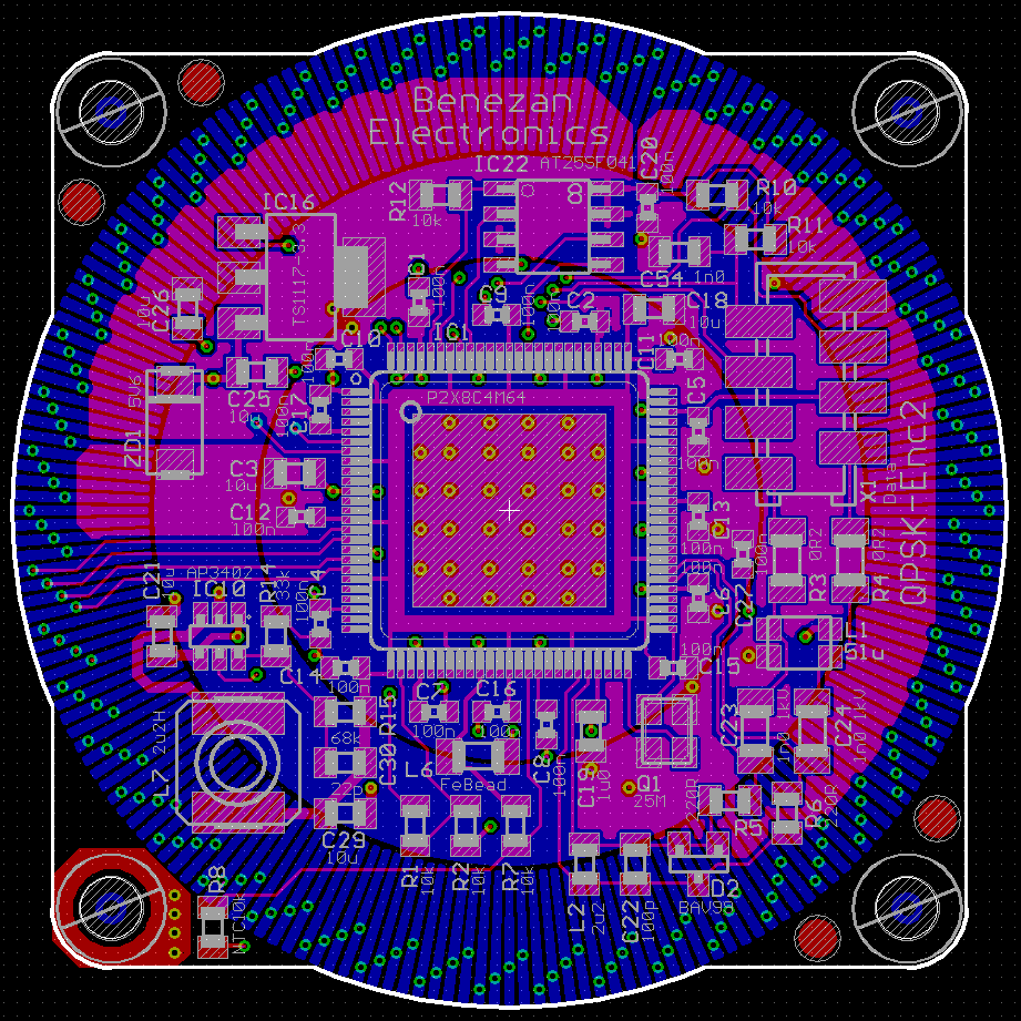
I've cut the number of "bycicle spokes" to half by combining two adjacent electrodes with a Y-pattern. The rest we will see...
Yeah, I hope they don't get the idea of optimizing it. "Oh what a bad design, so many useless traces that lead to nowhere. Let's cut all the traces that are not connected to any open pad to save copper..."
@ManAtWork said:
Yeah, I hope they don't get the idea of optimizing it. "Oh what a bad design, so many useless traces that lead to nowhere. Let's cut all the traces that are not connected to any open pad to save copper..."
They'd better not. That kinda thinking would screw a lot of rf designs.
Very nice pcbs! The filling is always tastier than the bread itself.
Hope the fab didn't messed with the moving disc outer perimeter too much, up to the point any attempt to fine tune its balancing would result in exposed copper surfaces.
I think, balancing or radial runout won't be a problem. The disc is spinning at 3000 RPM max. and a runout up to 0.1mm will be averaged out by the electrodes spread equally over the whole perimeter. Bending of the sisc and the resulting axial wobble is probably more critical. Any small change in the distance of the discs results in a big change of the capacitance. I have to make a hub on the lathe that centers and aligns the rotor well.
The Motor has a fixed bearing at the rear flange and a loose bearing at the front which is pre-tensioned axially by a corrugated spring washer. So the air gap between the encoder discs should stay relatively constant when the motor temperature changes and the rotor and shaft expand.
Is there potential high speed use of this? It just occurred to me that those disks look a lot like a Wimshurst Machine. Could static buildup become an issue here?
"Is there potential high speed use of this? It just occurred to me that those disks look a lot like a Wimshurst Machine. Could static buildup become an issue here?" - This is highly unlikely since the conductor configuration is not correct for a Wimshurst Machine. i.e. the combs and brushes. With a Wimshurst Machine all of the foil 'leafs' are electrically isolated. There is no 'transfer bar' and no comb pickups that are positioned correctly.
@Circuitsoft said:
Is there potential high speed use of this? It just occurred to me that those disks look a lot like a Wimshurst Machine. Could static buildup become an issue here?
In my design all even electrodes and all odd electrodes of the rotor are connected in a ring. At the stator every 4th electrodes are connected to one of 4 groups. So no electrostatic induction can happen. In a Wimshurst machine you need two counter-rotating discs and stationary brushes connecting opposite sides of the rotor.
I understand what the Goertzel mode does I think - essentially a single frequency FFT that delivers a complex value. I also understand capacity as a function of proximity, distance and dielectric constant. What I’m missing is why the former helps with the latter 😕
What effect do we measure here with phase or amplitude?
two periodical copper patterns, one fixed and one rotating form a capacitor that periodically changes capacity. A third pattern, shifted to the first one by 90° of the period forms another capacitor with the rotating pattern. So we have two signals that periodically change with the rotating rotor. These two signals are digitized and fed into the goertzel stage. The output gives the amplitude and the angle (polar coordinates) of the input signal (x/y coordinates). While the amplitude just shows that the system is working, the angle give a position information within one period of the signal. Thats all.
If the period of the signal corresponds to the motor poles the angle can be used to commutate the motor phases. Else there has to be a reference signal and then the angle can be counted and determine the rotor position at high resolution. So in this case Goertzel is not used as a fourier transformer.
Think of it as a circular potentiometer without end stops. Instead of the fixed contact at the ends it has 4 taps at 0, 90, 180 and 270°. We feed 4 signals +sin, +cos, -sin and -cos into the tap points. The rotor is the wiper and sees a "blended" signal that has a phase relationship proportional to the rotor angle. Now imagine that the potentiometer is not a resistive one with the wiper touching the resistive track but a capacitive one with the rotor electrode covering 90° and moving 0.1mm above the stator surface.
The actual design is differential. It has two opposite electrodes with opposite polarities. And instead of 4 electrodes (taps) there are 50 times 4 = 200 electrodes on the stator.
I've already got some signs of live from the encoder board. The capacitive sensor works quite well. However I have problems with the power supply. Although only two cogs are running, one transmitting some debug characters every 10ms and the other mostly waiting for the streamer, the board draws more than 200mA which causes too much voltage drop across the filters and protection resistors. I hoped 100mA was enough.
I have to find out if the current consumption is mainly caused by the 75 ohm DAC pins or by the 1.8V core. Decreasing the clock frequency is no option. I need 200MHz sampling rate to get reasonable resolution. And in the final application I even need one more cog for the QPSK communication.
Hmm, I have inserted a 0.2 ohm sense resistor into the 1.8V path. It shows 54mV voltage drop so that's 216mA for the core. I have vastly underestimated that. I thought that if I avoid busy waiting and heavy calculations I could get way below that. The cogs do almost nothing, only a CORDIC calculation once every 500µs and copying two longs to hubram. I can't believe that the streamer alone and the idling cogs draw so much current.
Anyway, if I replace the linear regulator for 1.8V with a switching one with better efficiency I can bring down the overall current draw near 100mA at 5V. I hoped to get away without that to avoid switching noise.
But still 8 cogs running at 200 MHz all the time so even when doing almost nothing, just switching states with the clock they surely must draw power. The P2 is not designed for the idle state operation, obviously
EDIT: I was also surprised the chip got really hot when pushed to the 350 MHz but it was working fine. I've seen power transistors falling off the board under load because of the overheating but you must have seen that too. The P2 remained on the board all right.
A stopped cog should not draw any power except the leakage current of all the CMOS gates. Well, at least the ALU, instruction decoder and all the control logic of the cog. Of course, the egg-beater still has to multiplex all those memory buses to the cogs even to those that don't do anything useful. And there a re a real lot of buses with lots of bits and long traces. I guess that this causes the majority of power consumption when idling at high frequencies.
@Maciek said:
I've seen power transistors falling off the board under load because of the overheating
Yes, that's a overtemperature fuse that cuts the circuit by de-soldering itself. But it doesn't always work, only if the current rises slowly. If the transistor case explodes you get thrust in the wrong direction.
...and I've just found out unintentionally that a P2 is still working at Vio=2.4V and Vcore=1.3V
@ManAtWork said:
....
...and I've just found out unintentionally that a P2 is still working at Vio=2.4V and Vcore=1.3V
That begs for further exploration because if confirmed over some wider clock frequency span it could be a worthy feature. It'll allow for lower (no, no, I do not say or mean low) power operation and the differences from the officially specified values are substantial. Even if the current does not drop at all, and it should, it is still a significant gain.
Maybe something like the UFO target board for the ChipWhisperer but with the P2 would be helpful as it allows for decoupling of the power supply pins ? Forget the original purpose of the ChipWhisperer but I am thinking purely in power profiling terms here.
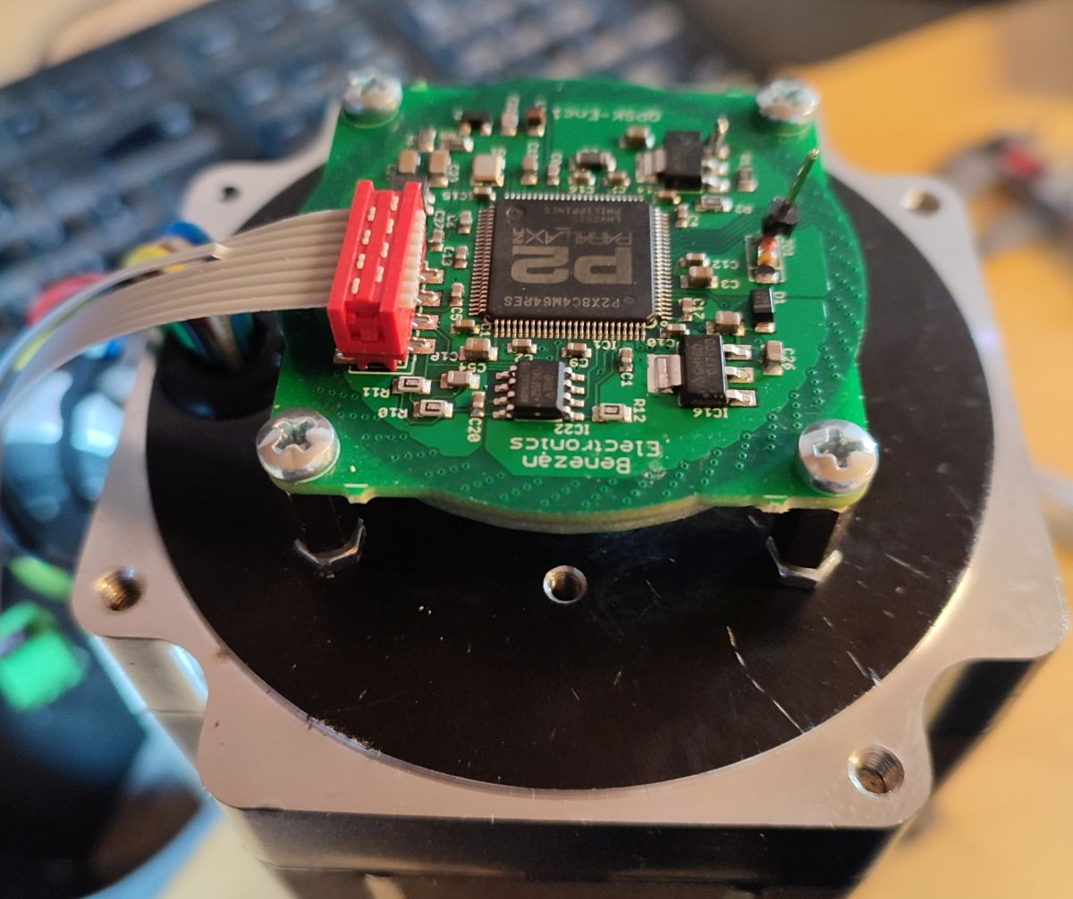
Today, I have mounted the encoder on a real motor. This was quite complicated because, for now, everything had to be adjustable. I glued the rotor PCB onto a brass hub with manual centering. The spacer bolts where the stator PCB is mounted are adjustable with lock nuts to fine tune the air gap between the two PCBs.
The air gap is relatively critical. A small change results in a large change of the signal amplitude. Although this does not affect the angle mesurement directly a smaller amplitude results in a lower signal to noise ratio and therefore in a lower resolution. I have set it to something in the 0.1 to 0.15mm range. Axial forces on the motor shaft or thermal expansion cause small changes of the air gap.
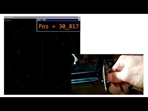
Here is a video demonstrating the performance. I manually turn the motor aprox. one full revolution. The displayed position value is composed of 10 bits from the angle output of the Goertzel calculations and the high order bits from a counter counting the wrap-arounds of the angle. There are 50 pole pairs per revolution so this translates to 50*1024=51200 counts per revolution.
There's plenty of resolution there for profiling microstepping performance, if that were useful
Its also interesting that you have that magnitude (amplitude) information, as well as phase. That could be used to perhaps measure thrust, or even mechanical shock should the load hit an obstacle or something.
State-of-the-art optical encoders have 17 to 22 bits resolution while cheap chinese ones have 1000..2500cpr (cycles or lines per revolution) or 4000 to 10000 counts/rev (~12 to 13 bits) so my encoder is somewhere in between. It's surely enough for closed loop steppers but doesn't beat high end servo systems, of course. For servos higher resolution is always better. Even if you don't need the resolution for positioning you get much better resolution of the velocity which is delta-position divided by delta time. If you need a velocity value once per millisecond that means you only get 6 bits of resolution from a 16 bit position value.
I doubt that the amplitude information can be taken for anything useful except for a rough sanity check if the encoder is still working within the design limits or anything has gone wrong (worn bearings, mechanical damage, too much dirt or oil/water in the air gap...).
I've made a new layout with a switching regulator for 1.8V instead of the LDO. And I've added a voltage divider to measure the supply voltage and an NTC to monitor motor temperature (near the mounting bolt).
Today I've tested the transmission over a real cable. With 75 ohm termination on each side of a 50m cable the signal level drops to ~0.8V on the sender side and ~0.5V at the receiver. There are almost no reflections but you can see the 250ns delay.
But the voltage drop is too high with the old layout and LDO regulators. At 200MHz the P2 draws too much current and the supply drops to 3.5V which is not enough for the LDO to output a stable 3.3V.


Comments
First, I have to find out if it works at all. If it doesn't I can save the extra work for trying to match impedances, trace length and so on. If it works very well at the first go I can also save it. Only if it works a little but not perfectly then I have to do some more iterations for optimizing.
I've cut the number of "bycicle spokes" to half by combining two adjacent electrodes with a Y-pattern. The rest we will see...
Some kind of a mix of Snowflake Daisy and tuning forks.
The pcb fab team will try to understand it as some kind of complex Christmas bulb, and will miss the RGBs and piezos.
Yeah, I hope they don't get the idea of optimizing it. "Oh what a bad design, so many useless traces that lead to nowhere. Let's cut all the traces that are not connected to any open pad to save copper..."
They'd better not. That kinda thinking would screw a lot of rf designs.
Today, the PCBs have arrived.
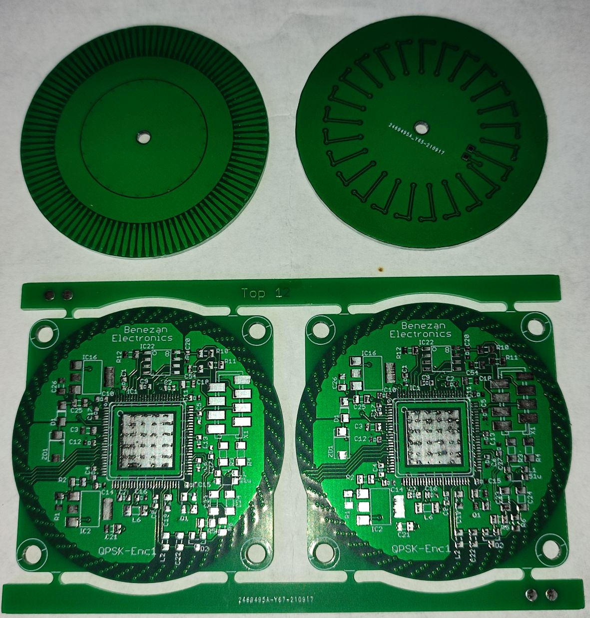
Very nice pcbs! The filling is always tastier than the bread itself.
Hope the fab didn't messed with the moving disc outer perimeter too much, up to the point any attempt to fine tune its balancing would result in exposed copper surfaces.
I think, balancing or radial runout won't be a problem. The disc is spinning at 3000 RPM max. and a runout up to 0.1mm will be averaged out by the electrodes spread equally over the whole perimeter. Bending of the sisc and the resulting axial wobble is probably more critical. Any small change in the distance of the discs results in a big change of the capacitance. I have to make a hub on the lathe that centers and aligns the rotor well.
Those look great Manatwork
I'm trying to work out how things mechanically couple, are there flanged bearings on the 4 corners of the stator that keep the rotor in position?
The Motor has a fixed bearing at the rear flange and a loose bearing at the front which is pre-tensioned axially by a corrugated spring washer. So the air gap between the encoder discs should stay relatively constant when the motor temperature changes and the rotor and shaft expand.
Is there potential high speed use of this? It just occurred to me that those disks look a lot like a Wimshurst Machine. Could static buildup become an issue here?
Maybe there'd be a way to mount a couple TVS diodes on the rotor and sink them into the shaft?
"Is there potential high speed use of this? It just occurred to me that those disks look a lot like a Wimshurst Machine. Could static buildup become an issue here?" - This is highly unlikely since the conductor configuration is not correct for a Wimshurst Machine. i.e. the combs and brushes. With a Wimshurst Machine all of the foil 'leafs' are electrically isolated. There is no 'transfer bar' and no comb pickups that are positioned correctly.
In my design all even electrodes and all odd electrodes of the rotor are connected in a ring. At the stator every 4th electrodes are connected to one of 4 groups. So no electrostatic induction can happen. In a Wimshurst machine you need two counter-rotating discs and stationary brushes connecting opposite sides of the rotor.
I understand what the Goertzel mode does I think - essentially a single frequency FFT that delivers a complex value. I also understand capacity as a function of proximity, distance and dielectric constant. What I’m missing is why the former helps with the latter 😕
What effect do we measure here with phase or amplitude?
two periodical copper patterns, one fixed and one rotating form a capacitor that periodically changes capacity. A third pattern, shifted to the first one by 90° of the period forms another capacitor with the rotating pattern. So we have two signals that periodically change with the rotating rotor. These two signals are digitized and fed into the goertzel stage. The output gives the amplitude and the angle (polar coordinates) of the input signal (x/y coordinates). While the amplitude just shows that the system is working, the angle give a position information within one period of the signal. Thats all.
If the period of the signal corresponds to the motor poles the angle can be used to commutate the motor phases. Else there has to be a reference signal and then the angle can be counted and determine the rotor position at high resolution. So in this case Goertzel is not used as a fourier transformer.
Think of it as a circular potentiometer without end stops. Instead of the fixed contact at the ends it has 4 taps at 0, 90, 180 and 270°. We feed 4 signals +sin, +cos, -sin and -cos into the tap points. The rotor is the wiper and sees a "blended" signal that has a phase relationship proportional to the rotor angle. Now imagine that the potentiometer is not a resistive one with the wiper touching the resistive track but a capacitive one with the rotor electrode covering 90° and moving 0.1mm above the stator surface.
The actual design is differential. It has two opposite electrodes with opposite polarities. And instead of 4 electrodes (taps) there are 50 times 4 = 200 electrodes on the stator.
I've already got some signs of live from the encoder board. The capacitive sensor works quite well. However I have problems with the power supply. Although only two cogs are running, one transmitting some debug characters every 10ms and the other mostly waiting for the streamer, the board draws more than 200mA which causes too much voltage drop across the filters and protection resistors. I hoped 100mA was enough.
I have to find out if the current consumption is mainly caused by the 75 ohm DAC pins or by the 1.8V core. Decreasing the clock frequency is no option. I need 200MHz sampling rate to get reasonable resolution. And in the final application I even need one more cog for the QPSK communication.
But you use only four (?) DACs so this shouldn't be causing so much current draw so the core would be the main suspect for me.
How are the other pins terminated/set up ?
Changing the DAC pin mode from P_DAC_75R_2V to P_DAC_990R_3V decreases the current consumption from 0.23 to 0.22A.
Hmm, I have inserted a 0.2 ohm sense resistor into the 1.8V path. It shows 54mV voltage drop so that's 216mA for the core. I have vastly underestimated that. I thought that if I avoid busy waiting and heavy calculations I could get way below that. The cogs do almost nothing, only a CORDIC calculation once every 500µs and copying two longs to hubram. I can't believe that the streamer alone and the idling cogs draw so much current.
Anyway, if I replace the linear regulator for 1.8V with a switching one with better efficiency I can bring down the overall current draw near 100mA at 5V. I hoped to get away without that to avoid switching noise.
But still 8 cogs running at 200 MHz all the time so even when doing almost nothing, just switching states with the clock they surely must draw power. The P2 is not designed for the idle state operation, obviously")
EDIT: I was also surprised the chip got really hot when pushed to the 350 MHz but it was working fine. I've seen power transistors falling off the board under load because of the overheating but you must have seen that too. The P2 remained on the board all right.
A stopped cog should not draw any power except the leakage current of all the CMOS gates. Well, at least the ALU, instruction decoder and all the control logic of the cog. Of course, the egg-beater still has to multiplex all those memory buses to the cogs even to those that don't do anything useful. And there a re a real lot of buses with lots of bits and long traces. I guess that this causes the majority of power consumption when idling at high frequencies.
Yes, that's a overtemperature fuse that cuts the circuit by de-soldering itself. But it doesn't always work, only if the current rises slowly. If the transistor case explodes you get thrust in the wrong direction.
...and I've just found out unintentionally that a P2 is still working at Vio=2.4V and Vcore=1.3V
That begs for further exploration because if confirmed over some wider clock frequency span it could be a worthy feature. It'll allow for lower (no, no, I do not say or mean low) power operation and the differences from the officially specified values are substantial. Even if the current does not drop at all, and it should, it is still a significant gain.
Maybe something like the UFO target board for the ChipWhisperer but with the P2 would be helpful as it allows for decoupling of the power supply pins ? Forget the original purpose of the ChipWhisperer but I am thinking purely in power profiling terms here.
Today, I have mounted the encoder on a real motor. This was quite complicated because, for now, everything had to be adjustable. I glued the rotor PCB onto a brass hub with manual centering. The spacer bolts where the stator PCB is mounted are adjustable with lock nuts to fine tune the air gap between the two PCBs.
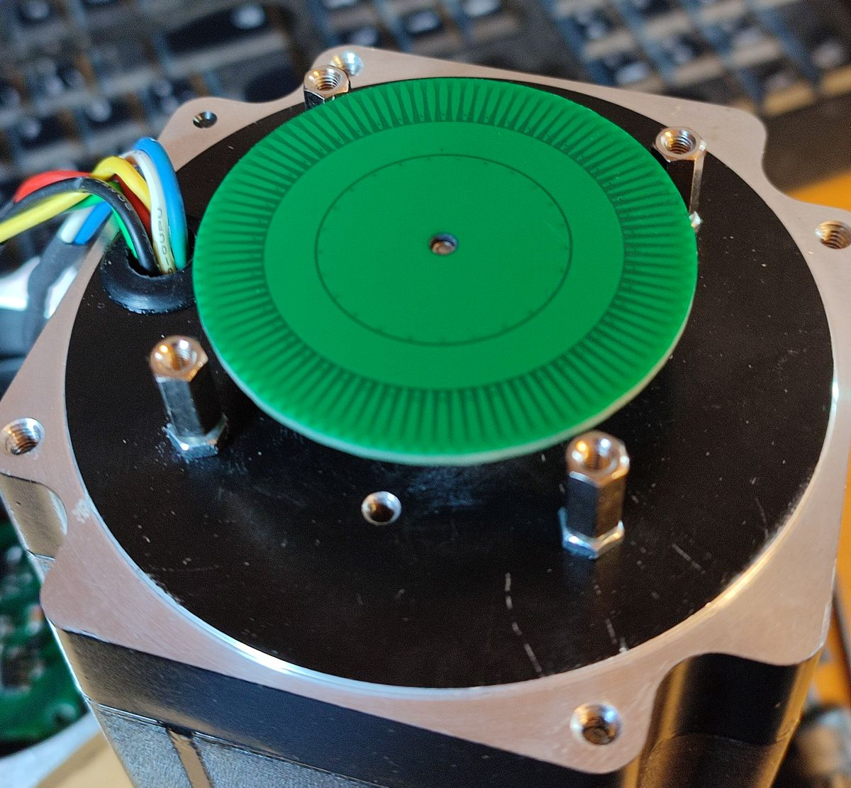

The air gap is relatively critical. A small change results in a large change of the signal amplitude. Although this does not affect the angle mesurement directly a smaller amplitude results in a lower signal to noise ratio and therefore in a lower resolution. I have set it to something in the 0.1 to 0.15mm range. Axial forces on the motor shaft or thermal expansion cause small changes of the air gap.
Here is a video demonstrating the performance. I manually turn the motor aprox. one full revolution. The displayed position value is composed of 10 bits from the angle output of the Goertzel calculations and the high order bits from a counter counting the wrap-arounds of the angle. There are 50 pole pairs per revolution so this translates to 50*1024=51200 counts per revolution.
Thats a really good result, congratulations.
There's plenty of resolution there for profiling microstepping performance, if that were useful
Its also interesting that you have that magnitude (amplitude) information, as well as phase. That could be used to perhaps measure thrust, or even mechanical shock should the load hit an obstacle or something.
State-of-the-art optical encoders have 17 to 22 bits resolution while cheap chinese ones have 1000..2500cpr (cycles or lines per revolution) or 4000 to 10000 counts/rev (~12 to 13 bits) so my encoder is somewhere in between. It's surely enough for closed loop steppers but doesn't beat high end servo systems, of course. For servos higher resolution is always better. Even if you don't need the resolution for positioning you get much better resolution of the velocity which is delta-position divided by delta time. If you need a velocity value once per millisecond that means you only get 6 bits of resolution from a 16 bit position value.
I doubt that the amplitude information can be taken for anything useful except for a rough sanity check if the encoder is still working within the design limits or anything has gone wrong (worn bearings, mechanical damage, too much dirt or oil/water in the air gap...).
I've made a new layout with a switching regulator for 1.8V instead of the LDO. And I've added a voltage divider to measure the supply voltage and an NTC to monitor motor temperature (near the mounting bolt).
Today I've tested the transmission over a real cable. With 75 ohm termination on each side of a 50m cable the signal level drops to ~0.8V on the sender side and ~0.5V at the receiver. There are almost no reflections but you can see the 250ns delay.
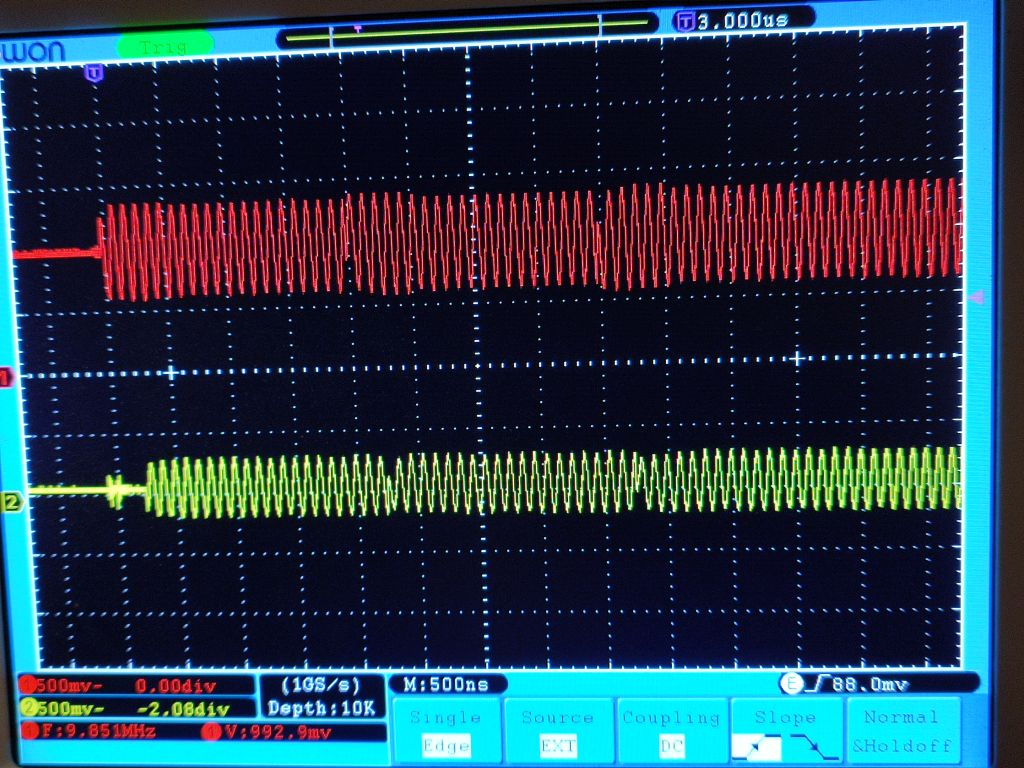
But the voltage drop is too high with the old layout and LDO regulators. At 200MHz the P2 draws too much current and the supply drops to 3.5V which is not enough for the LDO to output a stable 3.3V.