FLTL {#}D {WCZ} Syntax question
 Bob Drury
Posts: 236
Bob Drury
Posts: 236
in Propeller 2
FLTL {#}D {WCZ}
OUT bits of pins D[10:6]+D[5:0]..D[5:0] = 0. DIR bits = 0. Wraps within OUTA/OUTB. Prior SETQ overrides D[10:6]. C,Z = OUT bit.
For FLTL #21 DIR for Pin 21 =0 and no WRPIN command issued, would this do nothing? Would a
WRPIN ##P_LOW_FAST,#21 (default) , have to be issued first, then FLTL would cause the low side
of the Pin to float. Spin2 has pinfloat(#21) to float the pin 21 would FLTL #21 and FLTH #21 have to
be issued to float Pin 21. Trying to understand what FLT instructions are doing.
Regards
Bob (WRD)
Comments
The FLT part floats the pin ie DIR=0
The H/L part sets the OUT H/L.
It's use is so you can then just use DIR to Drive or not while OUT remains as H/L.
If pin is floating high impedance input what can Out do? I obviously misunderstand, maybe there is a different interpretation for float. I am thinking it disconnects the High an low multiplexers. (fast 1.5k 15k etc)
Regards
Bob (WRD)
I think what is being said:
FLTH output set High would remain HIGH on and by switching the DIR =0 the pin goes into a high impedance state or generates source signal when Pin DIR =1
FLTL output set Low would remain Low off and by switching the DIR=0 the pin goes into a high impedance state or generates sink signal when Pin DIR = 1.
If this is true then WHY FLTH and FLTL why not just FLT then set OUT H\L? I guess it save you from initially setting the output.
Would the use of this be in communication busses? Where bus or device is pull down resistor or bus is pull up resistor. That would mean the Multiplexer (fast 1.5k 15k etc)
has absolutely nothing to do with FLT commands and the default fast for High and Low on output drive would be used normally.
I am new to a lot of stuff .
Regards
Bob (WRD)
There's a set of instructions that are directly related:
OUTx
DIRx
FLTx
DRVx
OUTx controls just the OUTA/B register bit(s) for the affected pins
DIRx controls just the DIRA/B register bit(s) for the affected pins
FLTx and DRVx control both registers in a single 2 clock cycle instruction.
This allows better granularity in time sensitive code.
One example might be a duplex bus where you need to go from a high-impedance receive state to driving Low in most circumstances, but sometimes you need to drive High and the time taken is critical.
You could set the idle state with a FLTL and then use a DIRH instruction to switch to output for the majority case.
For the minority, but time sensitive case, instead of having to issue two instructions (OUTH, DIRH) you can simply issue a DRVH instruction (2 clocks), and on return to the idle state the FLTL correctly handles the return from both cases in only 2 clocks.
Addit: And it all cases you can use the WC/WZ/WCZ effect to capture the previous OUT state in the flag(s) being written.
This. I've often used FLTx to preset OUT register, not the output, to initial state before later using a DIRH on the same pins.
However, I've also seen a lot of lazy use of DRVx in place of OUTx, or FLTx and DRVx where DIRL and DIRH would have worked just fine. It's not unreasonable, the attitude is why track state of the individual components when a single instruction sets both at no extra cost.
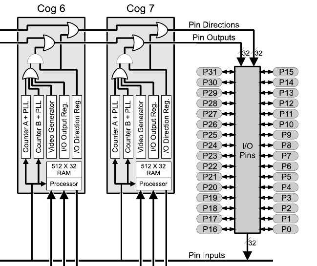
There is a drawing at the top of the Prop1 datasheet. It shows the logic from the OUT and DIR registers and how all the OUTs and DIRs from each Cog are merged on the way to the pins. The Prop2 has this same logic for its OUT and DIR registers as well.