@evanh said:
Hmm, I see the BITDAC pin setup is driving between Vdd and Vdd/2 rather than rail-to-rail. Same with Roger's driver. Why is that?
I think I had originally set it up to avoid exceeding the voltage range mentioned in the DVI spec and to bias it somewhere around the expected voltage. You can drive the output harder and it also typically works but my thought was that could potentially harm receive devices by exceeding their input range so I erred on the side of safety. I imagine it probably would not harm receivers in practice though, but can't rule it out. We don't have true CML outputs in the P2 so it uses this different drive method.
Just tried getting NTSC output from my Sega VDP emulation thing.
I've figured that this timing should be similar to real Sega Hardware, but that is irrelevant. What is relevant is that the total horizontal pixel count is such that there are an integer number of color cycles in a line (215+640)*6*4/90 == 228, which means that the color carrier should stay phase locked at all times. But it doesn't, on composite it gets terrible dotcrawl (svideo is kinda fine). My first suspicion was that the CFREQ just doesn't have enough precision, but that's clearly not it. At that clockrate, CFREQ rounding errors should only accumulate to one full cycle in at least 13 seconds, but whatever error is going on here accumulates a lot faster. So what's going on?
ntsc_timing 'NTSC resolution 640x240 60Hz - should be 100% timing the same as real MD?
' Not quite sure on the porch/sync widths, but the total is right
long 0'$01C732FB
long 53_693_175*6
'_HSyncPolarity___FrontPorch__SyncWidth___BackPorch__Columns
' 1 bit 7 bits 8 bits 8 bits 8 bits
long (video.SYNC_NEG<<31) | ( 53<<24) | ( 54<<16) | ( 108<<8 ) | (640/8)
'_VSyncPolarity___FrontPorch__SyncWidth___BackPorch__Visible
' 1 bit 8 bits 3 bits 9 bits 11 bits
long (video.SYNC_NEG<<31) | ( 0<<23) | ( 0<<20) | ( 12<<11) | 240
long (4*6) << 8 ' $0ccccccc+1
long (7<<24) + (40<<16)
long round(1.0/90.0 * 4_294_967_296.0) ' reserved for CFRQ parameter
I think I figured it, the serration pulses are a half-pixel short when the total pixels in a line are odd. Making the second set of pulses 1 px longer seems to keep the issue at bay.
@Wuerfel_21 said:
I think I figured it, the serration pulses are a half-pixel short when the total pixels in a line are odd. Making the second set of pulses 1 px longer seems to keep the issue at bay.
What did you mean about the "second set", are you talking about a timing difference between odd and even fields?
Well, there's one set of serration pulses, then sync pulses, then more serration pulses. If each of the second ones is made one pixel longer, the rounding error cancels out. The better solution would be to alternate each pulse, but adding more than 2 instructions to the sync routine seems to mess everything up, so, eh.
bitmask
ntsc1 rep #2, #5-0 'defaults to PAL
muxmask xcont sync_000, hsync1 'generate horizontal blanking/sync
offset xcont sync_001, hsync0
decod status, #31 'update status - in vertical sync
bpp setbyte status, fieldcount, #2 'update field counter in status
writestat wrlong status, statusaddr
ntsc2 rep #2, #5-0 'defaults to PAL
xcont sync_002, hsync1 'generate horizontal blanking/sync
xcont sync_003, hsync0
test m_vi,#1 wc ' TERRIBLE HACK
ntsc3 rep #3, #5-0 'defaults to PAL
xcont sync_000, hsync1 'generate horizontal blanking/sync
if_c xcont #1, hsync0 ' TERRIBLE HACK
xcont sync_001, hsync0
Yes the code is tight and finely balanced and doesn't take much changing to break it. I think my upcoming release with external RAM stuff probably has all COG space used so no more room.
After starting to test my Voyager PCB LCD output I think I've identified a reasonably simple, yet arcane way due to patching run time PASM code, to get DE pin output integrated with my DVI/VGA/TV driver so that parallel RGB panels or other devices like the TFP410 encoders can work with it. It's mainly a matter of patching some code below at setup time if the output type selected is parallel RGB. The key is to use sawtooth PWM smart pin output for the DE signal and set its duty cycle to either 0 or the number of visible pixels once per scan line depending on whether it is in blanking/sync or the active video region. I'll need to also sync it up to the HSYNC streamer output too, but this should be a one off thing at setup time.
I think I can also have analog DAC pins outputting video at the same time (which could be convenient), plus retain the existing VSYNC and HSYNC signals which some LCDs can use or require. I'll probably make all those outputs optional, along with the number of active parallel pixel bits using a pin mask which is useful if you have 6 bpp panels etc and want to free 6 pins vs using all 24 bits for video data. The clock will also be a PWM output (P2 clock needs to be an even multiple of the pixel rate to be able to generate a 50% duty cycle clock), so this implies 2x, 4x, 6x, ... divisors etc. I'll also have the clock and DE pins be invertable too.
I also want to support an optional pin for LCD backlight control using another PWM output whose duty cycle can be changed once per frame and add an API to control it. Main trick will be getting the streamer and DE PWM perfectly in sync at startup but I expect that is also doable with an initial streamer command whose execution time is a perfect multiple of the scan line period plus some extra clock cycles to align it, accounting for any internal latencies and the nominated porch sizes etc.
So I would change this sequence in my driver...
proghd2 sub m_sn, m_slim 'restores sync width (SD)
proghd3 setnib flipref, #0, #7 '...or restores back porch (HD)
nop 'must keep room for 18 instructions!
jmp #fieldloop 'continue on to a new field/frame
'--------------------------------------------------------------------------------------------------
' Subroutines
'--------------------------------------------------------------------------------------------------
hsync xzero m_sn, hsync1 'generate the sync pulse
wrlong status, statusaddr 'update the sync status per line
dobreeze xcont m_br, hsync0 'do breezeway before colour burst
setcq cq 'reapply CQ for PAL colour changes
doburst xcont m_cb, colourburst 'do the PAL/NTSC colour burst
flipref xor cq, palflipcq 'toggle PAL colour output per scanline
bp _ret_ xcont m_bv, hsync0 'generate the back porch
'..................................................................................................
blank_pal xor cq, palflipcq 'NEEDS TO BE EVEN DIST. FROM patchvbp!
blank call #hsync 'do hsync at the start of the line
xcont m_vi, hsync0 'generate blank line pixels
_ret_ djnz pa, #blank 'repeat to generate multiple lines
...into this code below with just 3 or 4 lines changed (some other code here already gets patched out for the VGA case so it doesn't make a lot of sense to analyze it as is)...
proghd2 sub m_sn, m_slim 'restores sync width (SD)
proghd3 setnib flipref, #0, #7 '...or restores back porch (HD)
jmp #fieldloop 'must keep room for 18 instructions!
mov de_pwm, vis_pixels
'--------------------------------------------------------------------------------------------------
' Subroutines
'--------------------------------------------------------------------------------------------------
hsync xzero m_sn, hsync1 'generate the sync pulse
wrlong status, statusaddr 'update the sync status per line
dobreeze wypin de_pwm, #depin
setcq cq 'reapply CQ for PAL colour changes
doburst xcont m_cb, colourburst 'do the PAL/NTSC colour burst
flipref xor cq, palflipcq 'toggle PAL colour output per scanline
bp _ret_ xcont m_bv, hsync0 'generate the back porch
'..................................................................................................
blank_pal mov de_pwm, #0 'NEEDS TO BE EVEN DIST. FROM patchvbp!
blank call #hsync 'do hsync at the start of the line
xcont m_vi, hsync0 'generate blank line pixels
_ret_ djnz pa, #blank 'repeat to generate multiple lines
...and I would be patching these existing calls to call one COG address earlier (can subtract one from fields in these locations) which is where the DE pin code sits.
lineloop
call #hsync-1 'do horizontal sync
and
patchvfp callpa #V_FP-0, #blank-1 'send vertical front porch lines
First attempt with this parallel RGB output method in my p2 video driver that was identified above got pretty close. Looks like I just need to phase align DE better at the start of line which should hopefully be straightforward enough with more tweaking.
Sending 100kB of a byte counting pattern at 800x480 image resolution in RGB8 colour mode @ 60Hz.
I would guess you're clocking to a specified clock frequency and native resolution, correct? Parallel/LVDS interfaces are the native LCD. Display's scan-converter is bypassed.
EDIT; I guess the dot clock has some flexibility. The panel will synchronously operate at whatever is pushed its way, within limits.
Newer panels, designed to handle DisplayPort environments, will likely have much wider range on refresh in particular.
@evanh said:
EDIT; I guess the dot clock has some flexibility. The panel will synchronously operate at whatever is pushed its way, within limits.
Yeah I suspect so. For now I am just running with a 40MHz dot clock, 240MHz P2 clock at native panel resolution and 60Hz refresh. This LCD panel is raw parallel RGB and doesn't include a scaler or anything fancy. It's a 7 inch Innolux display type (800x480 panel) and the data sheet mentions a typical data rate of 33.3Mpixels to 50Mpixels max, but no min input rate was specified. Once I get things to lock I'll probably play about with it to see what ranges it can take. It's only 6bits per colour so not the prettiest screen for graphics images etc, though it works okay with text.
@rogloh said:
First attempt with this parallel RGB output method in my p2 video driver that was identified above got pretty close. Looks like I just need to phase align DE better at the start of line which should hopefully be straightforward enough with more tweaking.
Sending 100kB of a byte counting pattern at 800x480 image resolution in RGB8 colour mode @ 60Hz.
Is it just because you're not driving it properly or is that the actual black level of that panel? Because, wow, that's some hot garbage then ;p
But yay for direct LCD drive, gotta bypass them trashy driver boards.
Yeah I investigated that issue and found out that I had used #3000000 instead of #$3000000 in a outa data pattern. Now that cyan is black and it looks a lot better. I've also been homing in on better alignment.
By the way @Wuerfel_21 , if your game code can be coaxed to run at 800x480 resolution with my video driver and uses USB input devices this little setup I have could make a portable game demo platform for a P2 and it has i2s or PWM audio output with internal speakers and/or line out.
@rogloh said:
By the way @Wuerfel_21 , if your game code can be coaxed to run at 800x480 resolution with my video driver and uses USB input devices this little setup I have could make a portable game demo platform for a P2 and it has i2s or PWM audio output with internal speakers and/or line out.
Which game? Spin Hexagon should JustWork(tm), just need to hack i2s into the audio streaming code (runs at flat 32 kHz, so it should be fine). If by USB input you mean USB gamepads, uhh, I don't think anyone got them working yet.
Projekt Menetekel likewise should work, but aside from being super unfinished as a whole (both the game and the VM that runs it), the video output is kinda suboptimal, because the game is designed for 256x224 with slightly wide pixels. On SDTV, the pixel clock is reduced to mostly (thin pixel text rendering on P1 necessitates a VSCL value that is divisible by 2, that being 10 for NTSC. 11 would fill the screen and that's what Spin Hexagon/VJET does on P1) fill the 4:3 screen horizontally, which is where the wide pixels come from, but that's not an option for digital outputs (and not really for VGA either, due to the tight sampling windows most LCD monitors have -> you just get uneven or very blurr pixels). The PC version has the same issue, but it looks less goofy in a desktop window than fullscreen on a wide display. The actual rendering fits neatly in 1 cog on P2, so I'm thinking of writing another cog that does gamma correct resampling to a slightly wider resolution (since the scale is already 2X to begin with, this shouldn't even be too terrible (and the graphics are generally drawn expecting some horizontal blurring from a CRT) , will have to try how that'd look. Would of course have to be gamma correct )
Infact, here's how resampling would look, except not gamma correct because Pain.NET.
This is linear interpolation vs. with gamma=2 (easy to implement... though I think there's a table-based approach that would work for arbitrary gamma curves, i.e. sRGB).
The gamma-aware one looks significantly more pleasant (look at the eyes!) and "CRT-like", I guess.
EDIT: Now that I think about it, I don't think I can do a lookup table - roots of sums come back to haunt me once more ;p
Well, if we're resampling for LCD, we might as well be aware of subpixels, right? Turns out that gets rid of most of the blur and if it does end up such that every subpixel needs its own QSQRT, it's effectively free. Though that implementation would probably eat all the remaining cogs, anyways...
@rogloh said:
By the way @Wuerfel_21 , if your game code can be coaxed to run at 800x480 resolution with my video driver and uses USB input devices this little setup I have could make a portable game demo platform for a P2 and it has i2s or PWM audio output with internal speakers and/or line out.
Which game? Spin Hexagon should JustWork(tm), just need to hack i2s into the audio streaming code (runs at flat 32 kHz, so it should be fine). If by USB input you mean USB gamepads, uhh, I don't think anyone got them working yet.
Yeah I was mainly thinking of this game. I thought it might have worked with a USB keyboard IIRC.
The audio doesn't necessarily have to hacked for i2s, though it's a nice to have feature as well going forward.
The way my own Voyager board works is that it has two source selection choices, one for the 3.5mm output and one that sources the amplifier.
Line out (3.5mm jack) - can be either sourced from the i2s DAC or from P2 GPIO audio
Amplifier in - can be either from P2 GPIO audio or whatever gets sent to the 3.5mm jack when it is not plugged in (plugging in cuts off the source to the amp, loaded down to gnd).
This selection was only done with solder jumpers, not some software selectable audio switches, which would have been cool now I think of it. Hmmm, maybe I can just try to bridge both with a capacitor on the jumper instead of solder to just merge both sources at once...might try that at some point too.
Projekt Menetekel likewise should work, but aside from being super unfinished as a whole (both the game and the VM that runs it), the video output is kinda suboptimal, because the game is designed for 256x224 with slightly wide pixels.
Yeah these mid sized LCD panels are sort of oddball (non 4:3) widescreen resolutions these days (800x480, 1024x600 etc). If it helps at all, in theory my video driver can at least pixel double up from 400x240 so there's always the black border option if the scan line rendering can effectively be centered in the middle using top, bottom and side borders.
Doubling to 512x448 (which fills most of the height on 480p) was never the issue (tripling would be, as text regions are always 512 wide), making the graphics not look oddly skinny is. They need to be widened by 15 to 20% or so. Problem is that I've figured out that doing interpolation+QSQRT per subpixel may not be viable. Maybe if hires text is sacrificed (reducing effective res to 512x224). But that's also not great. Then again, most people are aspect ratio blind, so I guess they wouldn't find it too terrible if the graphics are slightly skinny. But I myself am very peculiar about this sort of thing. Then again, I haven't even implemented it in the PC build yet, soooo ehhhhhhhh....
@rogloh said:
I thought it might have worked with a USB keyboard IIRC.
Yes, that's what it does work with. But it's easy to hack in pretty much anything, there's only 4 inputs.
I think it's 8:7 if you assume square pixels on a monitor. The 4:3 TV's didn't assume square pixels though. What was it, nominally something like 704 x 480 (but overscan affects this too) on a 4:3 CRT, at least for video. 640x480 fits better there.
Got the alignment and colours sorted now...apologies for poorly lit shot with overhead lighting flare. This is raw parallel RGB data going to the LCD panel (as 18bpp but in 256 colour palette mode sourced from that 720x480 Mario bmp file) using my hacked up p2 video driver as a proof of concept.
Update: Also added PWM control of the backlight pin and this works too.
One thing that bothers me a little is if the video driver ever gets overloaded and the streamer commands underrun this could cause a horizontal image offset to develop on LCD panels. An underrun doesn't typically happen unless you go out of your way to overload the driver (or run a pixel clock a little too slow for the features enabled). However if it ever happens, on a VGA or DVI output it can recover afterwards when the overload condition is removed and the sync pulses become stable again, but an LCD with it's DE signal being sent as PWM, it will not recover because the PWM pulse is synced once after initialization and stays fixed from then on. I can't really do much about this unless I somehow monitored for differences between HSYNC and DE pulse offsets and tried to restart or compensate the DE PWM phase accordingly. I don't really have the COG space or execution time to do that function all the time unless it was during the vertical sync perhaps. So if you ever overload the COG in the parallel RGB output mode, you probably would need a driver restart to recover.
Okay, after hitting my head against the problem for a while, I have achieved enlightenment and thus came to the realization that the palette doesn't contain a lot of very dark colors, so doing interpolation in 8 bit linear space is fine-ish, which means that BLNPIX can be used for the actual interpolation and a table lookup for linear-to-sRGB. Runs at ~36 cycles per output pixels, so viable in 3 cogs for 516x448 to 602x448, I guess? Lots of resource for such a minor thing.
Looks a bit like this for one (output-side) pixel:
' colora still set from previous iteration
rfbyte pixels+4
rdlut colorb,pixels+4 ' LUT contains palette in linear format
setpiv #PIV3
blnpix colora,colorb
getbyte tmp1,colora,#3
altgb tmp1,#linear2srgb
rolbyte outpixels+3
getbyte tmp1,colora,#2
altgb tmp1,#linear2srgb
rolbyte outpixels+3
getbyte tmp1,colora,#1
altgb tmp1,#linear2srgb
rolbyte outpixels+3
setbyte outpixels+3,#0,#3 ' debug wants xRGB, hardware wants RGBx, sigh....
' outpixel array gets burst written each loop
Nice job. It's good to see some use of the BLNPIX stuff. So far I've found that to be quite an expensive operation and burns COGs quickly if you want to use it in real time, and the alpha blending is also useful really only in the LUMA or R:G:B:0 modes or if RGBSQZ & RBGEXP is first used with 16bpp colour.
Having 3 COGs used up for scaling is a bit of a killer isn't it.


Comments
I think I had originally set it up to avoid exceeding the voltage range mentioned in the DVI spec and to bias it somewhere around the expected voltage. You can drive the output harder and it also typically works but my thought was that could potentially harm receive devices by exceeding their input range so I erred on the side of safety. I imagine it probably would not harm receivers in practice though, but can't rule it out. We don't have true CML outputs in the P2 so it uses this different drive method.
Oh, didn't know current mode was used. Just assumed it was LVDS. Shows I've never really looked hard at DVI/HDMI.
Huh, has a similarity to open-collector ... hehe, that works too
wrpin ##P_HIGH_FLOAT | P_LOW_1K5, #7<<6 + hdmi_baseWriting what might be my first serious Spin code, I've built my preferred video mode-set function:
PUB  modeset( basepin, width, height, vfreq ) | vblank, hfreq
'
' IMPORTANT:  Do CLKSET() before calling this
'
' NOTE:  Starts a new Cog to sequence the video output, and returns the cog_id
'
' NOTE:  Specified vertical refresh frequency is achieved only if there is
'   enough blanking time, otherwise it will be a lower frequency than requested
'
    vblank := vfreq * (width + hblank)
    vblank := (clkfreq/10 + vblank/2) / vblank - height
    vblank := vblank < 12 ? 12 : vblank

    c_pingrp := basepin addpins 7
    c_bv := vblank - 3          'post-vsync bulk vblanking
    c_dots := width
    c_lines := height
    m_bl := X_IMM_1X32_4DAC8 | X_PINS_ON | (basepin<<17) | 8        'hblank porch (symmetrical)
    m_sn := X_IMM_1X32_4DAC8 | X_PINS_ON | (basepin<<17) | (hblank - 16)    'hsync
    m_vi := X_IMM_1X32_4DAC8 | X_PINS_ON | (basepin<<17) | width        'border line

    hfreq := clkfreq / (10 * (hblank + width))  ' x10 assumes 10:1 DVI:pixel ratio
    vfreq := 10 * (hblank + width) * (vblank + height)
    vfreq := (clkfreq + vfreq/2) / vfreq
    debug( sdec(clkfreq), sdec(width), sdec(height), sdec(hblank), sdec(vblank), sdec(hfreq), sdec(vfreq) )

    return coginit( COGEXEC_NEW, @pgm_dvi )
PS:
hblank = 80a constant. All timing calculations assume a HDMI/DVI data link and reduced blanking.If this discussion is related to a different video driver, does it belong in a thread for that driver?
I don't have one, it's more a demo for what can be done.
Just tried getting NTSC output from my Sega VDP emulation thing.
I've figured that this timing should be similar to real Sega Hardware, but that is irrelevant. What is relevant is that the total horizontal pixel count is such that there are an integer number of color cycles in a line
(215+640)*6*4/90 == 228, which means that the color carrier should stay phase locked at all times. But it doesn't, on composite it gets terrible dotcrawl (svideo is kinda fine). My first suspicion was that the CFREQ just doesn't have enough precision, but that's clearly not it. At that clockrate, CFREQ rounding errors should only accumulate to one full cycle in at least 13 seconds, but whatever error is going on here accumulates a lot faster. So what's going on?ntsc_timing 'NTSC resolution 640x240 60Hz - should be 100% timing the same as real MD? ' Not quite sure on the porch/sync widths, but the total is right long 0'$01C732FB long 53_693_175*6 '_HSyncPolarity___FrontPorch__SyncWidth___BackPorch__Columns ' 1 bit 7 bits 8 bits 8 bits 8 bits long (video.SYNC_NEG<<31) | ( 53<<24) | ( 54<<16) | ( 108<<8 ) | (640/8) '_VSyncPolarity___FrontPorch__SyncWidth___BackPorch__Visible ' 1 bit 8 bits 3 bits 9 bits 11 bits long (video.SYNC_NEG<<31) | ( 0<<23) | ( 0<<20) | ( 12<<11) | 240 long (4*6) << 8 ' $0ccccccc+1 long (7<<24) + (40<<16) long round(1.0/90.0 * 4_294_967_296.0) ' reserved for CFRQ parameterI think I figured it, the serration pulses are a half-pixel short when the total pixels in a line are odd. Making the second set of pulses 1 px longer seems to keep the issue at bay.
What did you mean about the "second set", are you talking about a timing difference between odd and even fields?
Well, there's one set of serration pulses, then sync pulses, then more serration pulses. If each of the second ones is made one pixel longer, the rounding error cancels out. The better solution would be to alternate each pulse, but adding more than 2 instructions to the sync routine seems to mess everything up, so, eh.
bitmask ntsc1 rep #2, #5-0 'defaults to PAL muxmask xcont sync_000, hsync1 'generate horizontal blanking/sync offset xcont sync_001, hsync0 decod status, #31 'update status - in vertical sync bpp setbyte status, fieldcount, #2 'update field counter in status writestat wrlong status, statusaddr ntsc2 rep #2, #5-0 'defaults to PAL xcont sync_002, hsync1 'generate horizontal blanking/sync xcont sync_003, hsync0 test m_vi,#1 wc ' TERRIBLE HACK ntsc3 rep #3, #5-0 'defaults to PAL xcont sync_000, hsync1 'generate horizontal blanking/sync if_c xcont #1, hsync0 ' TERRIBLE HACK xcont sync_001, hsync0Yes the code is tight and finely balanced and doesn't take much changing to break it. I think my upcoming release with external RAM stuff probably has all COG space used so no more room.
After starting to test my Voyager PCB LCD output I think I've identified a reasonably simple, yet arcane way due to patching run time PASM code, to get DE pin output integrated with my DVI/VGA/TV driver so that parallel RGB panels or other devices like the TFP410 encoders can work with it. It's mainly a matter of patching some code below at setup time if the output type selected is parallel RGB. The key is to use sawtooth PWM smart pin output for the DE signal and set its duty cycle to either 0 or the number of visible pixels once per scan line depending on whether it is in blanking/sync or the active video region. I'll need to also sync it up to the HSYNC streamer output too, but this should be a one off thing at setup time.
I think I can also have analog DAC pins outputting video at the same time (which could be convenient), plus retain the existing VSYNC and HSYNC signals which some LCDs can use or require. I'll probably make all those outputs optional, along with the number of active parallel pixel bits using a pin mask which is useful if you have 6 bpp panels etc and want to free 6 pins vs using all 24 bits for video data. The clock will also be a PWM output (P2 clock needs to be an even multiple of the pixel rate to be able to generate a 50% duty cycle clock), so this implies 2x, 4x, 6x, ... divisors etc. I'll also have the clock and DE pins be invertable too.
I also want to support an optional pin for LCD backlight control using another PWM output whose duty cycle can be changed once per frame and add an API to control it. Main trick will be getting the streamer and DE PWM perfectly in sync at startup but I expect that is also doable with an initial streamer command whose execution time is a perfect multiple of the scan line period plus some extra clock cycles to align it, accounting for any internal latencies and the nominated porch sizes etc.
So I would change this sequence in my driver...
proghd2                     sub     m_sn, m_slim            'restores sync width (SD)
proghd3                     setnib  flipref, #0, #7         '...or restores back porch (HD)
                            nop                             'must keep room for 18 instructions!

                            jmp     #fieldloop              'continue on to a new field/frame

'--------------------------------------------------------------------------------------------------
' Subroutines
'--------------------------------------------------------------------------------------------------

hsync                       xzero   m_sn, hsync1            'generate the sync pulse
                            wrlong  status, statusaddr      'update the sync status per line
dobreeze                    xcont   m_br, hsync0            'do breezeway before colour burst
                            setcq   cq                      'reapply CQ for PAL colour changes
doburst                     xcont   m_cb, colourburst       'do the PAL/NTSC colour burst
flipref                     xor     cq, palflipcq           'toggle PAL colour output per scanline
bp          _ret_           xcont   m_bv, hsync0            'generate the back porch

'..................................................................................................
blank_pal                   xor     cq, palflipcq           'NEEDS TO BE EVEN DIST. FROM patchvbp!
blank                       call    #hsync                  'do hsync at the start of the line
                            xcont   m_vi, hsync0            'generate blank line pixels
            _ret_           djnz    pa, #blank              'repeat to generate multiple lines
...into this code below with just 3 or 4 lines changed (some other code here already gets patched out for the VGA case so it doesn't make a lot of sense to analyze it as is)...
proghd2                     sub     m_sn, m_slim            'restores sync width (SD)
proghd3                     setnib  flipref, #0, #7         '...or restores back porch (HD)
                            jmp     #fieldloop              'must keep room for 18 instructions!

                            mov     de_pwm, vis_pixels
'--------------------------------------------------------------------------------------------------
' Subroutines
'--------------------------------------------------------------------------------------------------

hsync                       xzero   m_sn, hsync1            'generate the sync pulse
                            wrlong  status, statusaddr      'update the sync status per line
dobreeze                    wypin   de_pwm, #depin
                            setcq   cq                      'reapply CQ for PAL colour changes
doburst                     xcont   m_cb, colourburst       'do the PAL/NTSC colour burst
flipref                     xor     cq, palflipcq           'toggle PAL colour output per scanline
bp          _ret_           xcont   m_bv, hsync0            'generate the back porch

'..................................................................................................
blank_pal                   mov     de_pwm, #0              'NEEDS TO BE EVEN DIST. FROM patchvbp!
blank                       call    #hsync                  'do hsync at the start of the line
                            xcont   m_vi, hsync0            'generate blank line pixels
            _ret_           djnz    pa, #blank              'repeat to generate multiple lines
...and I would be patching these existing calls to call one COG address earlier (can subtract one from fields in these locations) which is where the DE pin code sits.
lineloop
                            call    #hsync-1                  'do horizontal sync
and
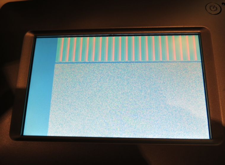
First attempt with this parallel RGB output method in my p2 video driver that was identified above got pretty close. Looks like I just need to phase align DE better at the start of line which should hopefully be straightforward enough with more tweaking.
Sending 100kB of a byte counting pattern at 800x480 image resolution in RGB8 colour mode @ 60Hz.
I would guess you're clocking to a specified clock frequency and native resolution, correct? Parallel/LVDS interfaces are the native LCD. Display's scan-converter is bypassed.
EDIT; I guess the dot clock has some flexibility. The panel will synchronously operate at whatever is pushed its way, within limits.
Newer panels, designed to handle DisplayPort environments, will likely have much wider range on refresh in particular.
Yeah I suspect so. For now I am just running with a 40MHz dot clock, 240MHz P2 clock at native panel resolution and 60Hz refresh. This LCD panel is raw parallel RGB and doesn't include a scaler or anything fancy. It's a 7 inch Innolux display type (800x480 panel) and the data sheet mentions a typical data rate of 33.3Mpixels to 50Mpixels max, but no min input rate was specified. Once I get things to lock I'll probably play about with it to see what ranges it can take. It's only 6bits per colour so not the prettiest screen for graphics images etc, though it works okay with text.
Is it just because you're not driving it properly or is that the actual black level of that panel? Because, wow, that's some hot garbage then ;p
But yay for direct LCD drive, gotta bypass them trashy driver boards.
Yeah I investigated that issue and found out that I had used #3000000 instead of #$3000000 in a outa data pattern. Now that cyan is black and it looks a lot better. I've also been homing in on better alignment.
By the way @Wuerfel_21 , if your game code can be coaxed to run at 800x480 resolution with my video driver and uses USB input devices this little setup I have could make a portable game demo platform for a P2 and it has i2s or PWM audio output with internal speakers and/or line out.
Which game? Spin Hexagon should JustWork(tm), just need to hack i2s into the audio streaming code (runs at flat 32 kHz, so it should be fine). If by USB input you mean USB gamepads, uhh, I don't think anyone got them working yet.
Projekt Menetekel likewise should work, but aside from being super unfinished as a whole (both the game and the VM that runs it), the video output is kinda suboptimal, because the game is designed for 256x224 with slightly wide pixels. On SDTV, the pixel clock is reduced to mostly (thin pixel text rendering on P1 necessitates a VSCL value that is divisible by 2, that being 10 for NTSC. 11 would fill the screen and that's what Spin Hexagon/VJET does on P1) fill the 4:3 screen horizontally, which is where the wide pixels come from, but that's not an option for digital outputs (and not really for VGA either, due to the tight sampling windows most LCD monitors have -> you just get uneven or very blurr pixels). The PC version has the same issue, but it looks less goofy in a desktop window than fullscreen on a wide display. The actual rendering fits neatly in 1 cog on P2, so I'm thinking of writing another cog that does gamma correct resampling to a slightly wider resolution (since the scale is already 2X to begin with, this shouldn't even be too terrible (and the graphics are generally drawn expecting some horizontal blurring from a CRT) , will have to try how that'd look. Would of course have to be gamma correct )
)
Infact, here's how resampling would look, except not gamma correct because Pain.NET.
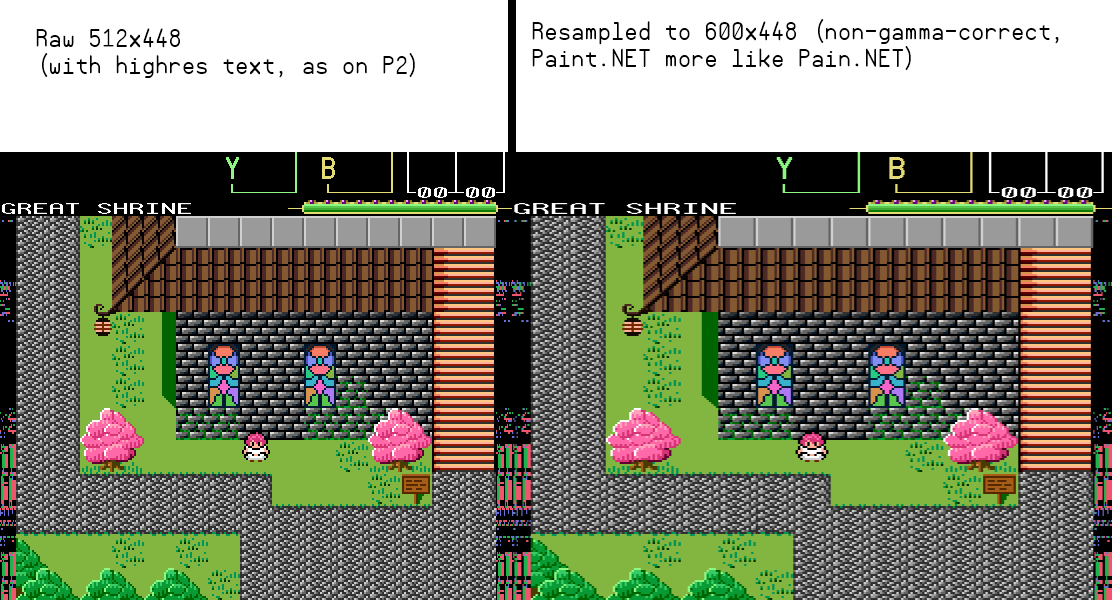
This is linear interpolation vs. with gamma=2 (easy to implement... though I think there's a table-based approach that would work for arbitrary gamma curves, i.e. sRGB).

The gamma-aware one looks significantly more pleasant (look at the eyes!) and "CRT-like", I guess.
EDIT: Now that I think about it, I don't think I can do a lookup table - roots of sums come back to haunt me once more ;p
Well, if we're resampling for LCD, we might as well be aware of subpixels, right? Turns out that gets rid of most of the blur and if it does end up such that every subpixel needs its own QSQRT, it's effectively free. Though that implementation would probably eat all the remaining cogs, anyways...
Yeah I was mainly thinking of this game. I thought it might have worked with a USB keyboard IIRC.
The audio doesn't necessarily have to hacked for i2s, though it's a nice to have feature as well going forward.
The way my own Voyager board works is that it has two source selection choices, one for the 3.5mm output and one that sources the amplifier.
Line out (3.5mm jack) - can be either sourced from the i2s DAC or from P2 GPIO audio
Amplifier in - can be either from P2 GPIO audio or whatever gets sent to the 3.5mm jack when it is not plugged in (plugging in cuts off the source to the amp, loaded down to gnd).
This selection was only done with solder jumpers, not some software selectable audio switches, which would have been cool now I think of it. Hmmm, maybe I can just try to bridge both with a capacitor on the jumper instead of solder to just merge both sources at once...might try that at some point too.
Yeah these mid sized LCD panels are sort of oddball (non 4:3) widescreen resolutions these days (800x480, 1024x600 etc). If it helps at all, in theory my video driver can at least pixel double up from 400x240 so there's always the black border option if the scan line rendering can effectively be centered in the middle using top, bottom and side borders.
Doubling to 512x448 (which fills most of the height on 480p) was never the issue (tripling would be, as text regions are always 512 wide), making the graphics not look oddly skinny is. They need to be widened by 15 to 20% or so. Problem is that I've figured out that doing interpolation+QSQRT per subpixel may not be viable. Maybe if hires text is sacrificed (reducing effective res to 512x224). But that's also not great. Then again, most people are aspect ratio blind, so I guess they wouldn't find it too terrible if the graphics are slightly skinny. But I myself am very peculiar about this sort of thing. Then again, I haven't even implemented it in the PC build yet, soooo ehhhhhhhh....
Yes, that's what it does work with. But it's easy to hack in pretty much anything, there's only 4 inputs.
256x224 at 4:3 screen aspect is 7:6 pixel aspect.
I think it's 8:7 if you assume square pixels on a monitor. The 4:3 TV's didn't assume square pixels though. What was it, nominally something like 704 x 480 (but overscan affects this too) on a 4:3 CRT, at least for video. 640x480 fits better there.
By "7:6 pixel aspect" I meant non-square pixels. The assumed part is the traditional fixed 4:3 screen aspect.
Got the alignment and colours sorted now...apologies for poorly lit shot with overhead lighting flare. This is raw parallel RGB data going to the LCD panel (as 18bpp but in 256 colour palette mode sourced from that 720x480 Mario bmp file) using my hacked up p2 video driver as a proof of concept.
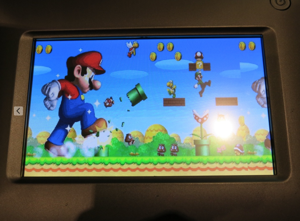
Update: Also added PWM control of the backlight pin and this works too.
One thing that bothers me a little is if the video driver ever gets overloaded and the streamer commands underrun this could cause a horizontal image offset to develop on LCD panels. An underrun doesn't typically happen unless you go out of your way to overload the driver (or run a pixel clock a little too slow for the features enabled). However if it ever happens, on a VGA or DVI output it can recover afterwards when the overload condition is removed and the sync pulses become stable again, but an LCD with it's DE signal being sent as PWM, it will not recover because the PWM pulse is synced once after initialization and stays fixed from then on. I can't really do much about this unless I somehow monitored for differences between HSYNC and DE pulse offsets and tried to restart or compensate the DE PWM phase accordingly. I don't really have the COG space or execution time to do that function all the time unless it was during the vertical sync perhaps. So if you ever overload the COG in the parallel RGB output mode, you probably would need a driver restart to recover.
Okay, after hitting my head against the problem for a while, I have achieved enlightenment and thus came to the realization that the palette doesn't contain a lot of very dark colors, so doing interpolation in 8 bit linear space is fine-ish, which means that BLNPIX can be used for the actual interpolation and a table lookup for linear-to-sRGB. Runs at ~36 cycles per output pixels, so viable in 3 cogs for 516x448 to 602x448, I guess? Lots of resource for such a minor thing.
Looks a bit like this for one (output-side) pixel:
' colora still set from previous iteration rfbyte pixels+4 rdlut colorb,pixels+4 ' LUT contains palette in linear format setpiv #PIV3 blnpix colora,colorb getbyte tmp1,colora,#3 altgb tmp1,#linear2srgb rolbyte outpixels+3 getbyte tmp1,colora,#2 altgb tmp1,#linear2srgb rolbyte outpixels+3 getbyte tmp1,colora,#1 altgb tmp1,#linear2srgb rolbyte outpixels+3 setbyte outpixels+3,#0,#3 ' debug wants xRGB, hardware wants RGBx, sigh.... ' outpixel array gets burst written each loopNice job. It's good to see some use of the BLNPIX stuff. So far I've found that to be quite an expensive operation and burns COGs quickly if you want to use it in real time, and the alpha blending is also useful really only in the LUMA or R:G:B:0 modes or if RGBSQZ & RBGEXP is first used with 16bpp colour.
Having 3 COGs used up for scaling is a bit of a killer isn't it.
Nice looking piccy there Roger.")
Yeah, a smartpin timing mismatch recovering during vblank sounds fine to me. It would primarily be a debugging tool anyway.