Maybe, active termination with some sort of soft-clipping would be better than passive, resitive termination. I have to do some experiments with different cable lengths. While QPSK should be relatively immune against noise ringing due to reflected waves could become a problem. 10MHz has a wavelength of 30m so a 7.5m cable can already form a 1/4 wave resonator.
At post #8 you showed us two types of available connectors, and also described the signal conductors as follows:
"The wire pair for communication is twisted and shielded..."
Resorting to Wikipedia for a first aproximation, I found a similar construction which shows VF = 66% (Belden 8723 twin shielded twisted pair stranded (polypropylene insulator)-entry).
This stands for something about 19.8 m wavelenght, based on a 10 MHz carrier.
Another version, now with only two twisted pairs, lists VF as 62% (due to the closer proximity between conductors centers and the underlying shield). Unfortunatelly, not any single-pair version available.
You are totally right. Speed of light is slower inside any solid or liquid material or in fact even in everything except a perfect vacuum. But the exact number of the wavelength doesn't matter here as we don't build antennas. I just wanted to express that the cable can be long enough that reflected waves could become a problem. Cables used in CNC machines with servo motors usually range from 1m to 50m. It has to work with any length in this range so you can't foresee the wavelength to cable length ratio for a paticular case, anyway.
Twisted pair cables usually have a (differential) impedance of 60 to 120 ohms. That's also not a perfect match to the 75 ohms (single ended) impedance of the P2 DAC outputs which results in a 150 ohms differential impedance. I think a little mismatch doesn't matter if the reflected energy is damped fast enough so it doesn't ring into the next bit too much. A bit pair is 1µs long and travels 200m at 66% of the speed of light. That is four times the longest cable. If we assume that less than half the energy is reflected then only <1/8 of the original signal strengt arrives 0.75µs later in the next bit at the receiver after being reflected 3 times. Shouldn't be a problem.
What makes me worry more is Murphy's law: If something can go wrong it will go wrong, eventually. If the encoder signals run in the same cable as the power for the motor then somebody will make a short between the two sooner or later.
An ambitious goal would be to design a protection circuit so that the encoder interface could survive a short to 230V AC. Well... survival without any damage would be perhaps possible but way too expensive. The wire pair has to provide 5V power at 100mA to the encoder so it has to have a low impedance.
But let's say we want to limit the damage so that it's at least repairable for little money. Self resetting or replaceable fuses are either too big or too expensive.
Use PTCs with low resistance that you need in your circuit. Otherwise, would only handling common mode spikes be okay? At the supply end you could transformer couple your signal to the output of an isolated dc/dc.
Well, yeah, an isolated supply would be the only real clean and safe solution. But it's even more expensive than resettable fuses. You need a DC/DC converter and a transformer that withstands the motor voltage. A cheap bifilar wound common mode choke is not enough.
Small fuses for 250V AC are expensive bcause they have to be able to cut several 10kA error currents. But the motor cables are not directly connected to mains. The IGBTs of the power stage would limit the max. short circuit current to some 100A and the power stage shuts down after <10µs if it detects overcurrent. So a much smaller fuse or even a simple 1206 resistor could do the job. It doesn't matter if it's totally wrecked as long as no holes get burned into the PCB. And of course, the P2 has to survive.
Yes, but you need an additional transformer to couple the signal to the DC line, at least on the "master" side. At the sensor side you don't need isolation so capacitive coupling is OK.
First version of the interface circuit:
As I already said, I'll use two pin pairs, one for sending and one for receiving. The sender pins drive in 75R DAC mode and stay enabled when receiving. In this case they act as termination resistors. C2 and C3 theoretically never see 1kV but I have theese values and I want to be sure that they never break down and limit the energy to the P2 pins. D1 limits the signal level to the receiver to +/-0.7Vp.
Innovation means creating something outside the norm.
The norm uses two connectors and cables per motor. The norm uses at least 4 wires for an encoder, some use even 14 (AB signals plus index and 3 hall sensors, all differential)! I simply don't want to. There are chances that it all doesn't work. But trying is fun.
Guess:
What he said. But using Goertzel 4 phases to do a heck of a lot better than 1 degree.
That wouldn't have been too bad to do in Kicad..It's just that any package geared for PCBs is going to be time-consuming.. Would take a couple of minutes in most mechanical cads though.. but good luck getting it onto a PCB afterward...
@ManAtWork said:
An optocoupler for 10MHz costs around $2. It can neither transmit analogue/sine signals nor can it do it bi-directional. A transformer can.
BTW, this took me more than 2 hours to draw. Who can guess what it is?
I feel like an Ethernet type transformer would simplify this circuitry a lot. The Bourns SM453229 has two coils that could easily be in series with your dc supply to inject your signal with 1500v isolation to the other coil. It costs usd0.85 from digikey. Might even be cheaper than other inductors you could use on the other end.
Unfortunately, it's only rated for 15mA common mode so your supply may need to be a higher dc voltage to get the power you need through it. Other Ethernet transformers may be better, especially if they're rated for PoE+.
@JRoark said:
Guess: 4 phase encoder baseplate with 1 degree resolution?
What I really want to know is what CAD package you used for that… and if its KICAD, can I watch next time? Lol
@"R Baggett" said:
Guess:
What he said. But using Goertzel 4 phases to do a heck of a lot better than 1 degree.
Yes, it's a 50CPR (cycles per revolution) capacitive encoder disc. I hope I can get at least 5000 counts per revolution out of that. I wonder if a three phase pattern would be better than the current four phase layout. The non-linearities resulting from imperfect interpolation should deform the perfect circle towards a hexagon for the 3-phase and towards a square for the 4-phase layout. So the 3-phase design should perfom better even if it has less electrodes.
And yes, ethernet transformers are a good idea. They are designed for exactly that purpose, coulpling HF signals onto twisted pair cables while providing isolation. Maybe 50mA are enough to power the P2 but 15mA aren't. The 75 ohm DAC outputs require some mA each. I'll do the first tests with my simple circuit without isolation. Maybe we can find a transformer that fits for the next iteration.
@Tubular said:
Love what you're doing, but I just wanted to mention these (analog) photocouplers for the record
I know there are analogue optocouplers. There are also cheap optocouplers and high-speed optocouplers. But the component-uncertainty rule says that you can't get all that attributes at once. Optocouplers are great for relatively low-speed (<1MBd) digital signals. For high speed signals, capacitive or inductive digital couplers like the ISO7720 or ADUM1301 are more cost-effective and less power-hungry. But for some special cases like coupling analogue signals without DC component transformers are just much easier. And they also can transfer energy and need no active amplifier.
I've used Eagle as CAD and an Excel sheet to transform the polar coordinates to cartesian. Eagle can import scripts ike that:
Most of them I have seen are inductive with two traces that weave in and out, fed in quadrature and decoded after that just like a standard resolver. but with a crazy strong drive (I made a fortune rebuilding those...) and LOTS of amplification on the receive coil which covers a very small portion of the driven coils. Sometimes the driven coil was 40' long, the rx coil maybe 6". Resolution was half a thousandth, if I remember correctly.. A large Mitsubishi mill. The big rotary table attachment had one in it made into a circle much like yours, but inductive..
What kind of separation between rotor and stator do you intend?
Perhaps I'm forgetting something really important, so it'll be easy to prove me wrong and I'll sure apologize for causing more confusion than clarifying, but, anyway...
As implemented at P2, Goertzel uses a 512-entry table, representing the angular movement between, says, 0 thru 359.9999 degrees. But the same can be said for (0 thru ((2 x Pi) - 0.0001)), or for (0 thru 399.9999 grads).
For 60hz, the 512 elements will get full usage after a total of 8.5333 line-cycles, where in a 50 Hz one, it'll need 10.24 line-cycles to get exhausted. The intrinsic granularity proportion (10.24 / 8.5333 = 1.2) is imposed by the difference between line frequencies, not the table.
So, if a revolving system is constructed to be in sync with the line frequency under which it runs, the solely diference in granularity would be due to the intrinsic design constrains.
This is in fact a solid argument to run each hardware environment under suitable multiples of the underlying line frequency it targets.
In case of your specific 50 Hz application, both 25.000 MHz and 20.000 MHz crystal oscillators can be seen as good choices, though a 60 Hz one can be improved by using, says, 19.2000 MHz and 24.000 MHz ones, wich would be also multiples of 50, in fact.
There are too many choices to be made; not all will perfectly match every "taste".
Capacitive and inductive designs both have advantages and disadvantages. Electric fields are easy to shield while magnetic fields are almost impossible to shield, at least for low frequencies. On the other hand, inductive designes usually have low impedance inputs and capacitive have high impedance inputs. The latter are more sensitive to parasitic effects. So both types require a careful layout with well balanced differential signals.
I don't think that 50 or 60Hz noise will become a problem. They are so far away from the pass-band of the filter. I'm more concerned about the PWM frequency of the power stage that drives the motor. 20kHz with steep edges can cause strong voltage spikes. All frequencies have to be selected so that none is a whole multiple of another. So sysclock=180MHz, QPSK carrier = 10.3MHz, encoder excitation = 1.9MHz, PWM = 22kHz is probably a better choice than 200MHz, 10MHz, 2MHz and 20kHz, for example.
I realy don't know, for sure; interactions between waves are a thoug subject. Aditive/subtrative constructions can appear from unnexpected sources, moreover when fixed digital delays are involved. The timing for each and every P2 pin does varies within some range, not particullary tunned to any frequency.
By the way, I know that commenting about anyone's design is easier than doing the actual work, but, anyway:
If possible, try to avoid such kind of impedance discontinuities, since they'll be cause of many reflections, given the high frequencies involved (Goertzel).
Also, any transitions would be improved by rounding (softening) them, up to a limit that don't impairs functionality.
The same can be said for any stubs, because of kickback effets on the waveshapes.
Ok, I've just read a bit of the "Goertzel self test" discussion. Of course, if a capacitive pad is touched with the finger, 60Hz noise is present everywhere because the human body has such a big surface and is exposed to all sorts of electromagnetic fields. In my encoder everything happens in the air gap between the rotor and stator PCB that are only tenths of a mm apart from each other. Both are multi-layer boards and the rear side or inner layers are used as shields. The metallic cover at the rear siode of the motor shields all external fields from the encoder. And there is no single center electrode like on the Goetzel accessory board but everything uses differential signals.
@Yanomani said:
I realy don't know, for sure; interactions between waves are a thoug subject. Aditive/subtrative constructions can appear from unnexpected sources, moreover when fixed digital delays are involved. The timing for each and every P2 pin does varies within some range, not particullary tunned to any frequency.
Delays are not a problem as long as they don't change too fast. As said in earlier posts the phase relation is auto-adjusted with a feedback loop. A fixed delay only causes a constant offset that can be totally cancelled.
If possible, try to avoid such kind of impedance discontinuities, since they'll be cause of many reflections, given the high frequencies involved (Goertzel).
Yes, especially long cables have to be terminated properly. A small difference of line vs. termination resistance doesn't do much harm as the QPSK modulation does not depend on the exact amilitude level and reflected waves only arrive at the receiver after being reflected 3 times. So most of the enery should be coasted away.
The same can be said for any stubs, because of kickback effets on the waveshapes.
I don't think a 5mm PCB trace stub causes any problems at <10MHz.
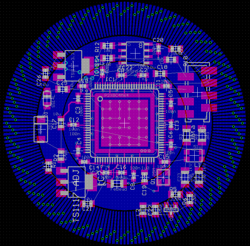
Routing is a bit tricky because the whole bottom layer is occupied by electrode areas. So vias are forbidden in the outer ring and should be minimized in the two inner electrode areas. Let's see if I manage to remove all "rubber bands" without the need for blind vias.
@Yanomani said:
P.S. Bycicle "cogs" teeth can be an example.
Hmm, while I'm pretty sure that those traces don't cause problems because of impedance mismatch or reflected waves I've noticed that the symetry is broken. The electrodes connected through vias have much more capacitance to ground than the ones connected without vias. I could balance this out by adding "meander traces" but I'm not sure if this would make it better or worse.
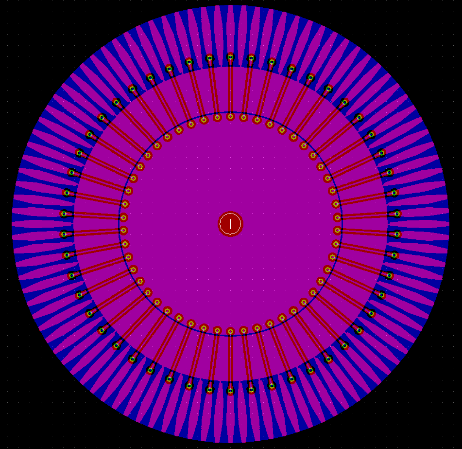
Meanwhile... Routing iof the stator disc is almost finished:
(inner layers not shown)
Sometimes one needs to resort to a different layer stack organization, and, eventually, the use of uneven thickness interposing ones, both for metal and insulation material, only to "ease" the needed adjustments. This can lead to an increased layer count, so, not the cheapest option, but, as alternatives "fade away"...
You're also dealing with differing total routing lenghts, due to the incrementing radial distancing, and, in this case, trapezoidal zig-zag seems to be not an option.
Perhaps it's one of such cases for trying some variations, and let to the design package the burden of recalculating the expected results.


Comments
At post #8 you showed us two types of available connectors, and also described the signal conductors as follows:
Resorting to Wikipedia for a first aproximation, I found a similar construction which shows VF = 66% (Belden 8723 twin shielded twisted pair stranded (polypropylene insulator)-entry).
This stands for something about 19.8 m wavelenght, based on a 10 MHz carrier.
Hope it helps a bit.
Henrique
https://en.wikipedia.org/wiki/Velocity_factor
P.S. As for today, Wikipedia's link to Belden's catalog seems to be broken, so here it is:
https://catalog.belden.com/techdatam/8723.pdf
Another version, now with only two twisted pairs, lists VF as 62% (due to the closer proximity between conductors centers and the underlying shield). Unfortunatelly, not any single-pair version available.
https://catalog.belden.com/techdatam/82723.pdf
You are totally right. Speed of light is slower inside any solid or liquid material or in fact even in everything except a perfect vacuum. But the exact number of the wavelength doesn't matter here as we don't build antennas. I just wanted to express that the cable can be long enough that reflected waves could become a problem. Cables used in CNC machines with servo motors usually range from 1m to 50m. It has to work with any length in this range so you can't foresee the wavelength to cable length ratio for a paticular case, anyway.
Twisted pair cables usually have a (differential) impedance of 60 to 120 ohms. That's also not a perfect match to the 75 ohms (single ended) impedance of the P2 DAC outputs which results in a 150 ohms differential impedance. I think a little mismatch doesn't matter if the reflected energy is damped fast enough so it doesn't ring into the next bit too much. A bit pair is 1µs long and travels 200m at 66% of the speed of light. That is four times the longest cable. If we assume that less than half the energy is reflected then only <1/8 of the original signal strengt arrives 0.75µs later in the next bit at the receiver after being reflected 3 times. Shouldn't be a problem.
What makes me worry more is Murphy's law: If something can go wrong it will go wrong, eventually. If the encoder signals run in the same cable as the power for the motor then somebody will make a short between the two sooner or later.
An ambitious goal would be to design a protection circuit so that the encoder interface could survive a short to 230V AC. Well... survival without any damage would be perhaps possible but way too expensive. The wire pair has to provide 5V power at 100mA to the encoder so it has to have a low impedance.
But let's say we want to limit the damage so that it's at least repairable for little money. Self resetting or replaceable fuses are either too big or too expensive.
Use PTCs with low resistance that you need in your circuit. Otherwise, would only handling common mode spikes be okay? At the supply end you could transformer couple your signal to the output of an isolated dc/dc.
Yeah, if you want that then make everything except the cable shield electrically isolated. Optocouplers for the signals and DC/DC converter for power.
Well, yeah, an isolated supply would be the only real clean and safe solution. But it's even more expensive than resettable fuses. You need a DC/DC converter and a transformer that withstands the motor voltage. A cheap bifilar wound common mode choke is not enough.
Small fuses for 250V AC are expensive bcause they have to be able to cut several 10kA error currents. But the motor cables are not directly connected to mains. The IGBTs of the power stage would limit the max. short circuit current to some 100A and the power stage shuts down after <10µs if it detects overcurrent. So a much smaller fuse or even a simple 1206 resistor could do the job. It doesn't matter if it's totally wrecked as long as no holes get burned into the PCB. And of course, the P2 has to survive.
I'd use prebuilt modules for DC/DC. Transformer is included then.
Yes, but you need an additional transformer to couple the signal to the DC line, at least on the "master" side. At the sensor side you don't need isolation so capacitive coupling is OK.
First version of the interface circuit:
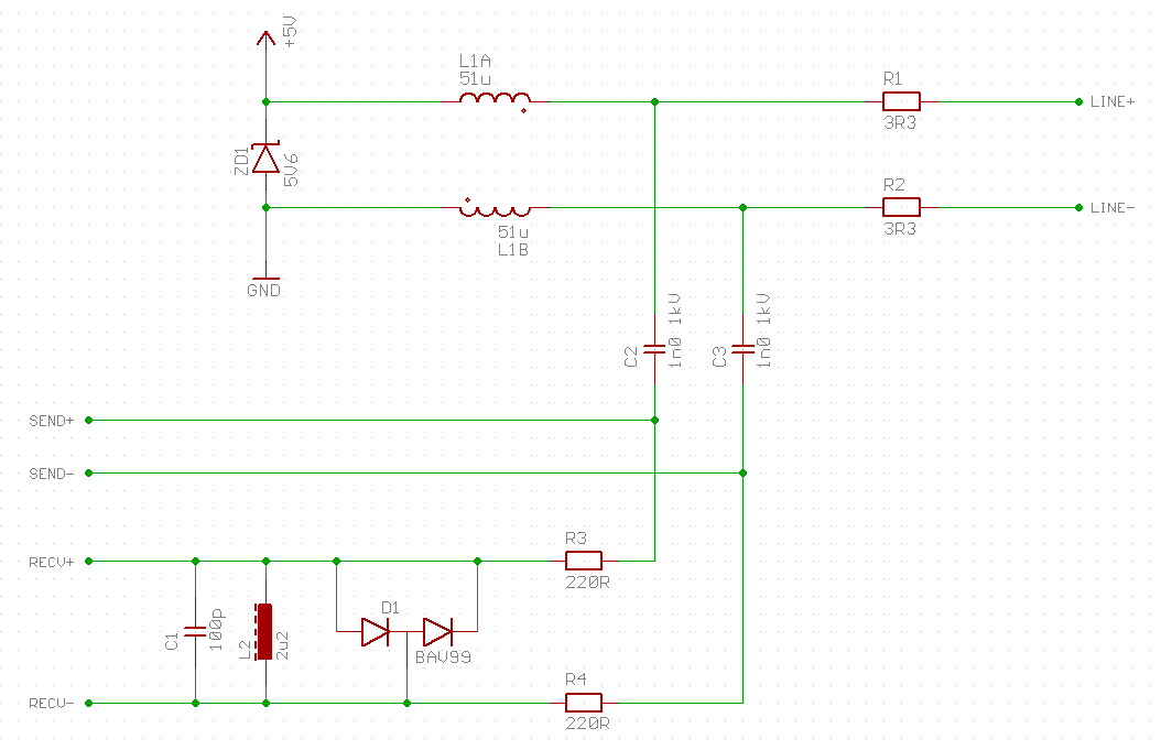
As I already said, I'll use two pin pairs, one for sending and one for receiving. The sender pins drive in 75R DAC mode and stay enabled when receiving. In this case they act as termination resistors. C2 and C3 theoretically never see 1kV but I have theese values and I want to be sure that they never break down and limit the energy to the P2 pins. D1 limits the signal level to the receiver to +/-0.7Vp.
Signals use optocouplers. They're cheap and easy.
An optocoupler for 10MHz costs around $2. It can neither transmit analogue/sine signals nor can it do it bi-directional. A transformer can.
BTW, this took me more than 2 hours to draw. Who can guess what it is?
Multiple opto's are the norm.
Innovation means creating something outside the norm.
The norm uses two connectors and cables per motor. The norm uses at least 4 wires for an encoder, some use even 14 (AB signals plus index and 3 hall sensors, all differential)! I simply don't want to. There are chances that it all doesn't work. But trying is fun.
Guess: 4 phase encoder baseplate with 1 degree resolution?
What I really want to know is what CAD package you used for that… and if its KICAD, can I watch next time? Lol
Guess:
What he said. But using Goertzel 4 phases to do a heck of a lot better than 1 degree.
That wouldn't have been too bad to do in Kicad..It's just that any package geared for PCBs is going to be time-consuming.. Would take a couple of minutes in most mechanical cads though.. but good luck getting it onto a PCB afterward...
Love what you're doing, but I just wanted to mention these (analog) photocouplers for the record
https://www.onsemi.com/pdf/datasheet/h11f3m-d.pdf
Transformers are wonderful though
I feel like an Ethernet type transformer would simplify this circuitry a lot. The Bourns SM453229 has two coils that could easily be in series with your dc supply to inject your signal with 1500v isolation to the other coil. It costs usd0.85 from digikey. Might even be cheaper than other inductors you could use on the other end.
Unfortunately, it's only rated for 15mA common mode so your supply may need to be a higher dc voltage to get the power you need through it. Other Ethernet transformers may be better, especially if they're rated for PoE+.
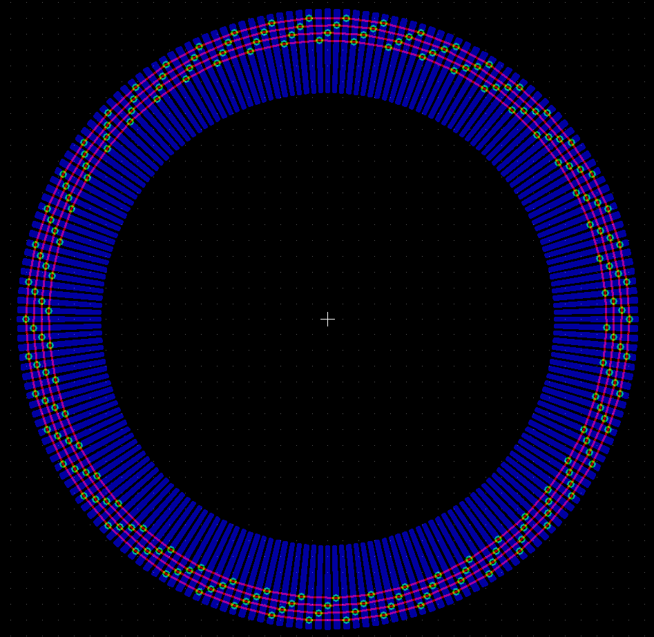
Yes, it's a 50CPR (cycles per revolution) capacitive encoder disc. I hope I can get at least 5000 counts per revolution out of that. I wonder if a three phase pattern would be better than the current four phase layout. The non-linearities resulting from imperfect interpolation should deform the perfect circle towards a hexagon for the 3-phase and towards a square for the 4-phase layout. So the 3-phase design should perfom better even if it has less electrodes.
And yes, ethernet transformers are a good idea. They are designed for exactly that purpose, coulpling HF signals onto twisted pair cables while providing isolation. Maybe 50mA are enough to power the P2 but 15mA aren't. The 75 ohm DAC outputs require some mA each. I'll do the first tests with my simple circuit without isolation. Maybe we can find a transformer that fits for the next iteration.
I know there are analogue optocouplers. There are also cheap optocouplers and high-speed optocouplers. But the component-uncertainty rule says that you can't get all that attributes at once. Optocouplers are great for relatively low-speed (<1MBd) digital signals. For high speed signals, capacitive or inductive digital couplers like the ISO7720 or ADUM1301 are more cost-effective and less power-hungry. But for some special cases like coupling analogue signals without DC component transformers are just much easier. And they also can transfer energy and need no active amplifier.
I've used Eagle as CAD and an Excel sheet to transform the polar coordinates to cartesian. Eagle can import scripts ike that:
Just finished the rotor disc:
(picture in post #42 shows the stator)
Most of them I have seen are inductive with two traces that weave in and out, fed in quadrature and decoded after that just like a standard resolver. but with a crazy strong drive (I made a fortune rebuilding those...) and LOTS of amplification on the receive coil which covers a very small portion of the driven coils. Sometimes the driven coil was 40' long, the rx coil maybe 6". Resolution was half a thousandth, if I remember correctly.. A large Mitsubishi mill. The big rotary table attachment had one in it made into a circle much like yours, but inductive..
What kind of separation between rotor and stator do you intend?
Perhaps I'm forgetting something really important, so it'll be easy to prove me wrong and I'll sure apologize for causing more confusion than clarifying, but, anyway...
As implemented at P2, Goertzel uses a 512-entry table, representing the angular movement between, says, 0 thru 359.9999 degrees. But the same can be said for (0 thru ((2 x Pi) - 0.0001)), or for (0 thru 399.9999 grads).
For 60hz, the 512 elements will get full usage after a total of 8.5333 line-cycles, where in a 50 Hz one, it'll need 10.24 line-cycles to get exhausted. The intrinsic granularity proportion (10.24 / 8.5333 = 1.2) is imposed by the difference between line frequencies, not the table.
So, if a revolving system is constructed to be in sync with the line frequency under which it runs, the solely diference in granularity would be due to the intrinsic design constrains.
This is in fact a solid argument to run each hardware environment under suitable multiples of the underlying line frequency it targets.
In case of your specific 50 Hz application, both 25.000 MHz and 20.000 MHz crystal oscillators can be seen as good choices, though a 60 Hz one can be improved by using, says, 19.2000 MHz and 24.000 MHz ones, wich would be also multiples of 50, in fact.
There are too many choices to be made; not all will perfectly match every "taste".
Hope it helps.
Henrique
A good reference, from the forums:
https://forums.parallax.com/discussion/169210/goertzel-self-test
Capacitive and inductive designs both have advantages and disadvantages. Electric fields are easy to shield while magnetic fields are almost impossible to shield, at least for low frequencies. On the other hand, inductive designes usually have low impedance inputs and capacitive have high impedance inputs. The latter are more sensitive to parasitic effects. So both types require a careful layout with well balanced differential signals.
I don't think that 50 or 60Hz noise will become a problem. They are so far away from the pass-band of the filter. I'm more concerned about the PWM frequency of the power stage that drives the motor. 20kHz with steep edges can cause strong voltage spikes. All frequencies have to be selected so that none is a whole multiple of another. So sysclock=180MHz, QPSK carrier = 10.3MHz, encoder excitation = 1.9MHz, PWM = 22kHz is probably a better choice than 200MHz, 10MHz, 2MHz and 20kHz, for example.
I realy don't know, for sure; interactions between waves are a thoug subject. Aditive/subtrative constructions can appear from unnexpected sources, moreover when fixed digital delays are involved. The timing for each and every P2 pin does varies within some range, not particullary tunned to any frequency.
By the way, I know that commenting about anyone's design is easier than doing the actual work, but, anyway:
If possible, try to avoid such kind of impedance discontinuities, since they'll be cause of many reflections, given the high frequencies involved (Goertzel).
Also, any transitions would be improved by rounding (softening) them, up to a limit that don't impairs functionality.
The same can be said for any stubs, because of kickback effets on the waveshapes.
P.S. Bycicle "cogs" teeth can be an example.
Ok, I've just read a bit of the "Goertzel self test" discussion. Of course, if a capacitive pad is touched with the finger, 60Hz noise is present everywhere because the human body has such a big surface and is exposed to all sorts of electromagnetic fields. In my encoder everything happens in the air gap between the rotor and stator PCB that are only tenths of a mm apart from each other. Both are multi-layer boards and the rear side or inner layers are used as shields. The metallic cover at the rear siode of the motor shields all external fields from the encoder. And there is no single center electrode like on the Goetzel accessory board but everything uses differential signals.
Delays are not a problem as long as they don't change too fast. As said in earlier posts the phase relation is auto-adjusted with a feedback loop. A fixed delay only causes a constant offset that can be totally cancelled.
Yes, especially long cables have to be terminated properly. A small difference of line vs. termination resistance doesn't do much harm as the QPSK modulation does not depend on the exact amilitude level and reflected waves only arrive at the receiver after being reflected 3 times. So most of the enery should be coasted away.
I don't think a 5mm PCB trace stub causes any problems at <10MHz.")
Routing is a bit tricky because the whole bottom layer is occupied by electrode areas. So vias are forbidden in the outer ring and should be minimized in the two inner electrode areas. Let's see if I manage to remove all "rubber bands" without the need for blind vias.
Now I can see the whole picture!
Overall nice work, indeed!
Looks like the photoplotter aperture wheels we used on Gerber photo plotters:
Reminds me of my Gerber Aperture wheels off the photoplotter.
https://forums.parallax.com/discussion/164106/so-how-much-do-you-know-about-gerber-data
Hmm, while I'm pretty sure that those traces don't cause problems because of impedance mismatch or reflected waves I've noticed that the symetry is broken. The electrodes connected through vias have much more capacitance to ground than the ones connected without vias. I could balance this out by adding "meander traces" but I'm not sure if this would make it better or worse.
Meanwhile... Routing iof the stator disc is almost finished:
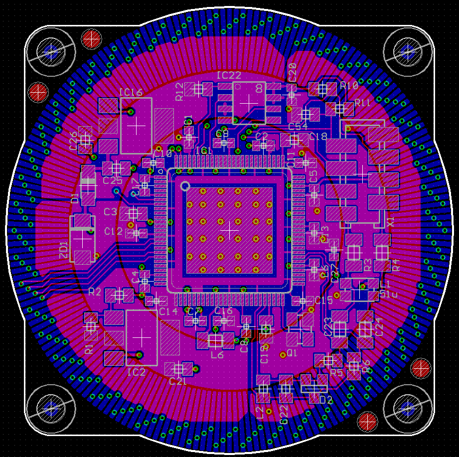
(inner layers not shown)
Sometimes one needs to resort to a different layer stack organization, and, eventually, the use of uneven thickness interposing ones, both for metal and insulation material, only to "ease" the needed adjustments. This can lead to an increased layer count, so, not the cheapest option, but, as alternatives "fade away"...
You're also dealing with differing total routing lenghts, due to the incrementing radial distancing, and, in this case, trapezoidal zig-zag seems to be not an option.
Perhaps it's one of such cases for trying some variations, and let to the design package the burden of recalculating the expected results.
Fingers crossed here...