Hmm, darn, I keep banging into the problem of needing to track fluctuating calibration. Which breaks the contiguous decimation, and that destroys Sinc2/3 performance advantage.
After I now have got Kiss with SD, and after understanding a little bit of smart pins, (what a learning curve here...) I could now do some measurements. (With Taqoz)
Input on P14, Sync2 Filtering mode, cpu clock=200MHz, 12bits resolution with 2048 clocks sample period.
wrpin ##%100011_0000000_00_11000_0,#adcpin '\ gain=1
'\ wrpin ##%100101_0000000_00_11000_0,#adcpin '\ gain=10
'\ wrpin ##%100111_0000000_00_11000_0,#adcpin '\ gain=100
wxpin #%01_1011,#adcpin '\ 1011 12 bits 2048 clocks
Pin14 at voltage divider between 0 and 3.3V with two 4k7 and a ceramic capacitor 10nF to GND. Open breadboard setup, no special shielding.
Results:
Gain 100; Gain 10; Gain 1;
Average 1830,121212; 2046,717172; 2077,727273;
Standard Dev 4,91825572; 0,742862693; 0,469871494;
Enob 8,53957674; 11,42792856; 12,11045243;
Well, 1650mV/2048/(Gain=100)= 0,008mV resolution. 4,9*0,008= 0,04mV=V.RMS. If I hook up my oscilloscope in parallel, it says about 1...2mV V.RMS. It does measure a lot of very high frequency stuff.
At this level shielding and grounding become very tricky, I think. This was an open breadboard setup. At P2 the length of the measurement was only 100 samples at 98kHz, so low frequency problems are not visible.
Very interesting! Between Gain=1 and Gain=10 there is not much difference so I think the performance of the Gain=3.1 mode can be guessed by interpolation. But could you please also test the Gain=31 mode? It would be good to know if there is some "barrier" or fixed noise floor that limits the ENOB.
You've done remarkably well if this is a breadboard setup, but if you're going to repeat you should at least stiffen your voltage divider, perhaps 22 ohms 1/4 watt resistor would be a lot better at keeping external noise out.
The input impedance of the ADC at 100x mode is something like 3~5k ohm i believe, and you're feeding it with around 2k, and ideally you want that an order of magnitude or two down. Many 16 bit ADCs require driving from an external op amp in order to meet the specs
I base the 22 ohms on dissipating around 0.12 watts each, about half the rating of a standard 1/4w resistor
Finally, does your breadboard have a metal backing plate? If so are you currently grounding it, or leaving it unconnected? You have a third option of tying it to the 1.65V node, which should also help quieten things down
So I have done additional measurements with a modified setup:
1. Modified the length of the sample from 100 to 3000 ==> which made things very much worse, because 50Hz is now included.
2. Wrapped the whole breadboard + Kiss in aluminium foil for shielding ==> which helped a lot!
3. Included gain factors 3,16 and 31,6
I am astonished, that the average value was different between shielded and non-shielded setup which needed perhaps half an hour.
Ok, interesting. So we can get a little more of information with the higher gain modes but not as much as a theoretically ideal could get according to the gain numbers. It's sort of a warped wall instead a brick wall.
Foil vs not-foil looks pretty much the same to me. The earlier average for gain=1 was just over 2000, that's still the same. The ENOB is 0.3 better. For gain=100 the average improved maybe 70 but ENOB dropped by 0.1.
Today I got my Sinc3 PASM code working. So I did an evaluation with Sinc3 mode 512cycles, 391kHz sample rate, 18bit. This was disappointing for me. The benefit is not a higher ENOB. Instead it seems possible to reach 12bit ENOB with a higher sampling rate? (Which I do not need for audio analysis.)
Edit: If I average 4 samples of Sinc3 512cycles I end up with ENOB=12,41 which is not better than Sinc2 filter 2048 cycles.
Edit2: After some more experimenting for Audio analysis I will use Sinc2 Sampling Mode with 4096 cycles 13 bits. This gives also about ENOB 12,4 but I can work with a shorter buffer to reach low frequencies and due to the slower sample rate it is possible to do the sampling in Forth without Pasm.
From others' comments I believe it's possible to improve the situation by band passing to higher frequencies. Remove, say, everything below 1 kHz, using just the 1 kHz to 100 kHz range, then that should see a marked improvement in ENOB.
@evanh said:
From others' comments I believe it's possible to improve the situation by band passing to higher frequencies. Remove, say, everything below 1 kHz, using just the 1 kHz to 100 kHz range, then that should see a marked improvement in ENOB.
Yes, I can believe that. When I used a short buffer of only 100 samples (=1/1000Hz length @100kHz sample rate), the standard deviation and the ENOB have been much better, because they use the difference to the average of that sample. So this acted as high pass like your suggestion.
Unfortunately my project wants to analyse the harmonic distortion, that is generated by guitar effects from a sine test-signal into this device. For the analysis I go with the test-frequency=base-frequency and the double and the three-fold frequency into Goertzel filters of the distorted signal. So this has to work for about >40 Hz. It should give results to < 0,5 pc level of the harmonics in relation to the base level. So this needs about ENOB>=8 but not only for the maximum level, as the signal level into the guitar effect is to be varied for this analysis. (The software Goertzel algorithm adds noise for the long buffer, but this is a different field....)


Comments
Hmm, darn, I keep banging into the problem of needing to track fluctuating calibration. Which breaks the contiguous decimation, and that destroys Sinc2/3 performance advantage.
After I now have got Kiss with SD, and after understanding a little bit of smart pins, (what a learning curve here...) I could now do some measurements. (With Taqoz)
Input on P14, Sync2 Filtering mode, cpu clock=200MHz, 12bits resolution with 2048 clocks sample period.
wrpin ##%100011_0000000_00_11000_0,#adcpin '\ gain=1
'\ wrpin ##%100101_0000000_00_11000_0,#adcpin '\ gain=10
'\ wrpin ##%100111_0000000_00_11000_0,#adcpin '\ gain=100
wxpin #%01_1011,#adcpin '\ 1011 12 bits 2048 clocks
Pin14 at voltage divider between 0 and 3.3V with two 4k7 and a ceramic capacitor 10nF to GND. Open breadboard setup, no special shielding.
Measurement of 100 samples.
Formula used: ENOB= LOG( average; 2 ) - LOG ( Standard_deviation ; 2 )
Results:
Gain 100; Gain 10; Gain 1;
Average 1830,121212; 2046,717172; 2077,727273;
Standard Dev 4,91825572; 0,742862693; 0,469871494;
Enob 8,53957674; 11,42792856; 12,11045243;
Ouch! The degradation at gain 100 is a full 8x worse than gain 10. Makes that gain select near worthless.
Well, 1650mV/2048/(Gain=100)= 0,008mV resolution. 4,9*0,008= 0,04mV=V.RMS. If I hook up my oscilloscope in parallel, it says about 1...2mV V.RMS. It does measure a lot of very high frequency stuff.
At this level shielding and grounding become very tricky, I think. This was an open breadboard setup. At P2 the length of the measurement was only 100 samples at 98kHz, so low frequency problems are not visible.
Very interesting! Between Gain=1 and Gain=10 there is not much difference so I think the performance of the Gain=3.1 mode can be guessed by interpolation. But could you please also test the Gain=31 mode? It would be good to know if there is some "barrier" or fixed noise floor that limits the ENOB.
You've done remarkably well if this is a breadboard setup, but if you're going to repeat you should at least stiffen your voltage divider, perhaps 22 ohms 1/4 watt resistor would be a lot better at keeping external noise out.
The input impedance of the ADC at 100x mode is something like 3~5k ohm i believe, and you're feeding it with around 2k, and ideally you want that an order of magnitude or two down. Many 16 bit ADCs require driving from an external op amp in order to meet the specs
I base the 22 ohms on dissipating around 0.12 watts each, about half the rating of a standard 1/4w resistor
Finally, does your breadboard have a metal backing plate? If so are you currently grounding it, or leaving it unconnected? You have a third option of tying it to the 1.65V node, which should also help quieten things down
So I have done additional measurements with a modified setup:
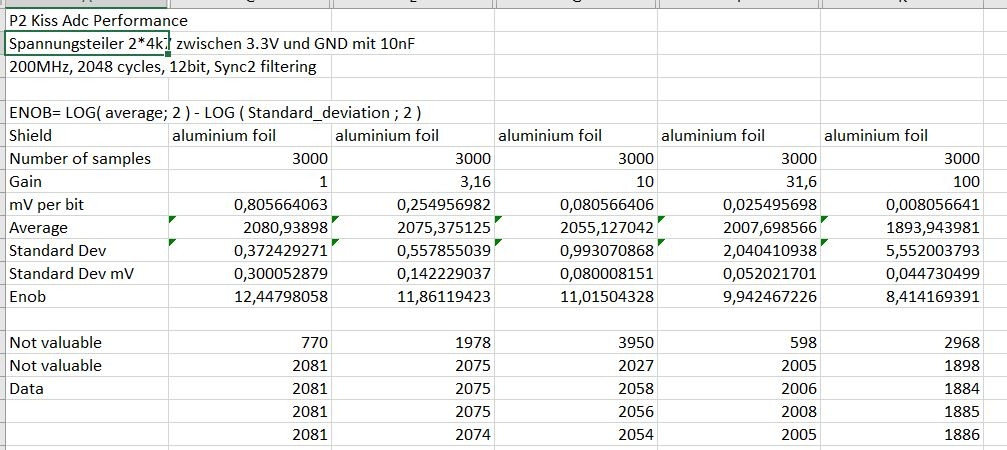
1. Modified the length of the sample from 100 to 3000 ==> which made things very much worse, because 50Hz is now included.
2. Wrapped the whole breadboard + Kiss in aluminium foil for shielding ==> which helped a lot!
3. Included gain factors 3,16 and 31,6
I am astonished, that the average value was different between shielded and non-shielded setup which needed perhaps half an hour.
Ok, interesting. So we can get a little more of information with the higher gain modes but not as much as a theoretically ideal could get according to the gain numbers. It's sort of a warped wall instead a brick wall.
Foil vs not-foil looks pretty much the same to me. The earlier average for gain=1 was just over 2000, that's still the same. The ENOB is 0.3 better. For gain=100 the average improved maybe 70 but ENOB dropped by 0.1.
Today I got my Sinc3 PASM code working. So I did an evaluation with Sinc3 mode 512cycles, 391kHz sample rate, 18bit. This was disappointing for me. The benefit is not a higher ENOB. Instead it seems possible to reach 12bit ENOB with a higher sampling rate? (Which I do not need for audio analysis.)
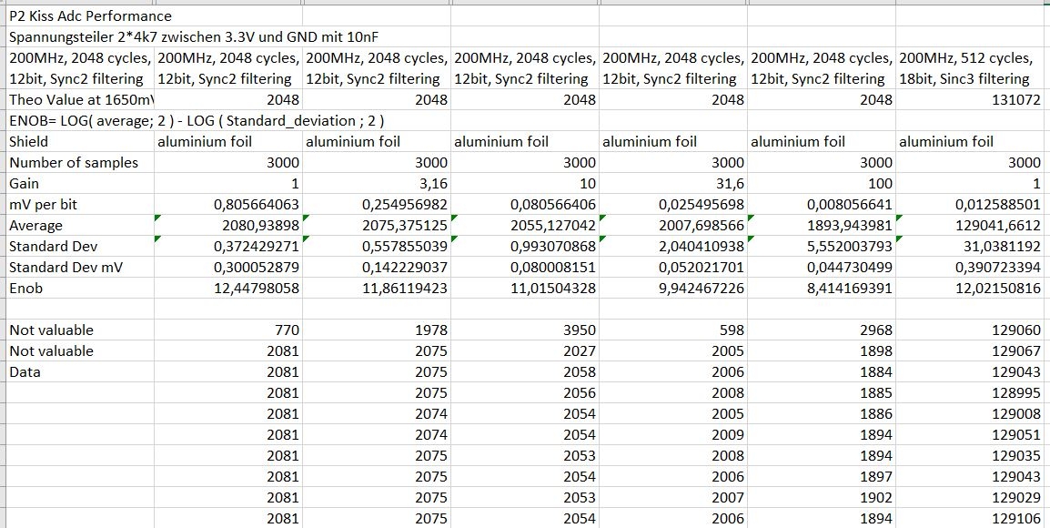
Edit: If I average 4 samples of Sinc3 512cycles I end up with ENOB=12,41 which is not better than Sinc2 filter 2048 cycles.
Edit2: After some more experimenting for Audio analysis I will use Sinc2 Sampling Mode with 4096 cycles 13 bits. This gives also about ENOB 12,4 but I can work with a shorter buffer to reach low frequencies and due to the slower sample rate it is possible to do the sampling in Forth without Pasm.
From others' comments I believe it's possible to improve the situation by band passing to higher frequencies. Remove, say, everything below 1 kHz, using just the 1 kHz to 100 kHz range, then that should see a marked improvement in ENOB.
Yes, I can believe that. When I used a short buffer of only 100 samples (=1/1000Hz length @100kHz sample rate), the standard deviation and the ENOB have been much better, because they use the difference to the average of that sample. So this acted as high pass like your suggestion.
Unfortunately my project wants to analyse the harmonic distortion, that is generated by guitar effects from a sine test-signal into this device. For the analysis I go with the test-frequency=base-frequency and the double and the three-fold frequency into Goertzel filters of the distorted signal. So this has to work for about >40 Hz. It should give results to < 0,5 pc level of the harmonics in relation to the base level. So this needs about ENOB>=8 but not only for the maximum level, as the signal level into the guitar effect is to be varied for this analysis. (The software Goertzel algorithm adds noise for the long buffer, but this is a different field....)