Hello everyone,
I was able to repair my defective 6th panel (it was the upper one for me).
I re-soldered some components with flux (no clean) and now it's 98% ok.
@"Stephen Moraco"
The "demo MultiPanel" is very cool. Now I have something to play with again. In one view they are all numbered P0-P5 and in the other view they are labeled Front, Left, Right, Back and Top, Bottom. Great! Is there already a scroll command in the driver to make the font run vertically?
Is it also possible to distribute a picture over all 6 panels. If so, it could be in a future demo.
Many Thanks,
I'm looking forward to the next driver version
@Butterman3D said:
Is any one still working on there cube? I just started to begin working on mine to see just if I can build too as well.
If you have any questions we will help you here. Twyyx will definitely bring out updates for the cube, this is still a prototype. I also run mine with a power supply to test it, but will soon try it with rechargeable batteries.
Great to here and thank you for welcoming me along. So far in my prototype model I been trying to construct a stable reliable brackets that can keep cube it all together in place along with slots for electronic boards battery and wires which I don't want to over think on it right now because by having a very compact space makes my imagination limited for now. I came a cross old Nintendo Game cube refabricate some of the parts and create brackets that can keep 5 of the panels together without losing too much space and hopeful soon will be ready for meat and potatoes.
I do have plans to release updates and more docs from the prototyping phase. It's really nice to see others jumping in and pushing on the idea together.
Once I get back into the workshop, I can make more progress. Sometimes life happens while you're planning other things!
I do have plans to release updates and more docs from the prototyping phase. It's really nice to see others jumping in and pushing on the idea together.
Once I get back into the workshop, I can make more progress. Sometimes life happens while you're planning other things!
Wow super impressive! Puts my cappy effort to shame!
is it allowed to adapt the 3D models (stl) by "Bob Miller kbob "to other panels and then to post them here?
Do I have to ask him for permission before?
If so, how? I can't find a button / link on Github to write to him.
I like its structure and I would then like to test adaptations.
is it allowed to adapt the 3D models (stl) by "Bob Miller kbob "to other panels and then to post them here?
Do I have to ask him for permission before?
If so, how? I can't find a button / link on Github to write to him.
I like its structure and I would then like to test adaptations.
greeting
Andreas
Andreas,
I've found Bob's contact info and reached out to him. I'll let you know if he responds, even if he doesn't join us here.
I've found Bob's contact info and reached out to him. I'll let you know if he responds, even if he doesn't join us here.
Hello, World!
Thanks for letting me know about this group, Twyyx. I haven't read this thread yet, but I'm excited to see more cubists.
AndreasS, you're welcome to use my STLs any way you want. I can also provide the Fusion 360 files, if you happen to use F360. (You can also export to other CAD formats.)
Edit: the F360 files are already in my Github repository. I forgot -- haven't really touched this project in the last two years.
Do we have anyone with a bit of time and experience with image manipulation and video conversion?
I'm reasonably good with working the direct hardware control and I have more work to do with enabling various kinds of panels to work with our driver.
I would like to invite someone to help us who can contribute a layer of image processing and maybe even video frame conversion to show more on our panels.
I'll work with the person joining us to provide any driver support you need to help in doing this.
I've already provided example handling of bmp24 bit image conversion to panel display (example in driver demos). I've already provided panel-set pixel setting at row, column, and panel specific (single panel within panel-set) pixel setting at row, column.
There is an image request earlier in this thread. I can envision that the activities would be:
Convert the image to bmp24 but scaled to maybe 4x the 64x64 panel size per panel side
Load the entire image then tease out the 6 panels of sub-images -OR- dice up the image into 6 smaller image files
Load the image files
For each image: for all pixel groups in the image: calculate the average RGB value for each 4x4 pixel-group and write to row, col of the specific panel
After the files for all the panels are loaded commit to panel-set (causing the cube image to be displayed)
I'm hoping we can welcome a person, with this kind of experience to draw on, to come and play with us on this cube project!
AndreasS that frame looks both very familiar and strangely different. Are you holding all six sides on with magnets? The screws were a pain to use.
Will the Propeller generate graphics standalone, or will it connect to a host of some sort?
And what did you end up doing for a power supply? I designed my own board*, as I couldn't find anything off the shelf that fit and generated enough current. Calculations showed that it would want 24 amps @ 5V, but it ended up being closer to 18 @ 4V.
*I designed a board, then an experienced EE took pity on me and re-laid it out much better.
Also, I expected a lot of heat inside the box, and planned to use HTPLA to handle the temperatures. But it isn't hot at all. The temp. sensors on the Raspberry Pi read maybe 5℃ warmer than they would in free air. I guess running the LEDs at 4V had a lot to do with that.
ok i then print 5 panels holder/frame and the new skeleton with holes for the magnets. I don't know how the connection to the propeller board will be made later, maybe Twyyx and Stephen Moraco can say something about it. Can we use your power board? If so, could you recommend a circuit board and compile a parts list for the parts?
ok i then print 5 panels holder/frame and the new skeleton with holes for the magnets. I don't know how the connection to the propeller board will be made later, maybe Twyyx and Stephen Moraco can say something about it. Can we use your power board? If so, could you recommend a circuit board and compile a parts list for the parts?
You can use the power board. I got my PCBs from LCSC. I used 2 oz. outer copper layers for high current. It has components on both sides. I populated one side with a stencil and reflow oven, then hand soldered the other side. The heavy copper layers made hand soldering slow.
The board has two power supplies. It's a 25 amp 4 volt supply for the LEDs, and a separate 5 volt, 3 amp supply for the Raspberry Pi and FPGA board. You can probably replace the CPU supply with something much lower current, as the TI chip I used (LMZ14203) is expensive.
The board also has soft power circuitry for a Raspberry Pi that you don't care about, An IMU, and a battery meter (ADC), both connected via I2C. I never got around to using the IMU or meter.
So I guess the power board is more of a guideline than a drop-in solution for you. (-:
The hinged lid and magnetic clasps work very well. The magnets are removable so you can print many iterations of the plastic, and move the magnets to the new versions. The hinges work well, are simple, and don't take much interior space. The way the hinges attach to the lid is the best I could do with 3D printed parts. It's an extra assembly step, but it works and has been reliable.
The tool free assembly for the circuit boards and battery work pretty well. Things are very tight, and there are a lot of wires, but that's more or less unavoidable. You'll be a little better off since you have a single CPU board (maybe?) instead of a Raspberry Pi plus FPGA board plus HUB75 board.
I made a "clip" to hold the Raspberry Pi's connector in place. I shouldn't have bothered -- the friction in the connector is stronger than the clip.
We talked about making a Pi Hat that would incorporate the FPGA and one to three HUB75 connectors, but that didn't happen. It would have freed up some space inside, though.
You probably figured out that the Raspberry Pi holder, power board holder, and battery holder each have leaf springs in their plastic so that you can just bend the springs to insert/remove the components. When I took it apart and put it together many times, the plastic springs got weak and eventually I had to replace those components. I took it to a trade show where people did exactly that for two days. I reprinted those parts.
I have extra batteries and extra battery holders. I can swap out a battery in just a few seconds.
The "skeleton" design -- a frame that goes around the edges of the cube and has attachment points. I have mixed feelings about it. As I mentioned, it is a real pain to fit nylon locknuts onto all the internal screws when attaching the panels. The beveled LED panel frames are time consuming to put on and off, and they are too specific to the exact model of LED panel that I used. And the 3D model is complex, as you know if you've opened it in Fusion 360. So assembling the skeleton, frames and hinges is very slow, but installing the electronics and wiring is very fast.
If I did it again, I think I'd just have the frame go around the perimeter of the LED panel. The internal ribs don't add anything. (They were used in early versions of the design, but became useless.) The way the lid hinges attach do use the ribs there, so those ribs would have to stay.
The screws are captive between the frames and the LED panels. I did it that way so that overtightening a screw couldn't force it into the LED PCB. Seemed like a good idea at the time...
But for a 3D printed chassis, I think it's the right idea. I've seen (photos only) other designs for P2.5 LED panels that use laser cut plywood frames, and those look simpler and easier to assemble. But the P2.5 panels are much bigger (twice the internal volume), so there are fewer constraints.
I don't know anything about the Propeller (sorry!) but I thought the Raspberry Pi and FPGA combo worked pretty well. The Pi has network connectivity, a development environment, good I/O, and a GPU for those graphics that can use it. I used a Pi 3 instead of a Pi Zero, as I thought four CPU cores would make animation smoother than a single core. (No idea whether I was right, but the Shaderboy renderer does use four threads and the GPU.) The FPGA has rock solid timing to drive the HUB75 signals. I know Greg Davill has made some LED cubes using Cortex-M micro controllers, so you can certainly get by with less compute power.
I made all my own cables, and I made each one to exactly the needed length. The ribbon cables were fast and easy. I hand crimped the others. The power cables were not too bad. The Raspberry Pi power + data cable was the worst, 10 conductors in a 2mm pitch connector.
Thanks for giving me an excuse to remember all the fun I had making this project.
can someone tell me whether such a power conditioning is absolutely necessary or can I connect the 2 LiPo batteries directly, in parallel with the 5v step-down regulators?
I would very much NOT do that - the "5V" step-downs are never going to be perfectly 5V. One might be 5.001V and the other 4.999V.
Now, that may not sound like much difference, but if the wiring between them is 0.001 ohms (not unreasonable for thick stranded copper) you're going to be throwing away TWO AMPS of current as heat - and sooner or later one of them's going to fail, closely followed by the other one.
@Scroungre said:
I would very much NOT do that - the "5V" step-downs are never going to be perfectly 5V. One might be 5.001V and the other 4.999V.
Now, that may not sound like much difference, but if the wiring between them is 0.001 ohms (not unreasonable for thick stranded copper) you're going to be throwing away TWO AMPS of current as heat - and sooner or later one of them's going to fail, closely followed by the other one.
Don't do that. S.
OK thank you for the info. I didn't know that. What if I connected three panels to each battery? I do not know whether the lipos are undercharged and thus break or, in the worst case, start to burn.
Hello,
I have no idea how the cube will work later with the 2 batteries.
I would like to construct the frame as suggested by "kbob".
All frames with magnets, but I don't know how we can then stow all components in the cube.
And does the board get WiFi or Bluetooth support so that you can later send pictures or videos to the cube?
So far I am not able to play my own picture or video on the "Propeller 2 Evaluation Board" & cube.
I know that it will take some time until the cube is ready for use,
but i would like to see a few steps forward.
Unfortunately I cannot serve with software knowledge.
I want to see more progress too. I need more workshop space, and have been waiting for renovations to happen. It still hasn't happened yet. Maybe next week they'll finally start. I have been building up my workshop tooling, but it got to a point where I simply didn't have enough of a functioning workspace to tame all the tools and components. I'm going to start trying to be more active here on the weekends with updates even if I have to juggle a bit.
The next step from me will be power supply testing; verifying how long a 7.4V LiPo pack will work with the 5V DC/DC converter before dropping out under load.
I have a vacuum chamber now to test stabilizing panels with UV resistant clear resin. This might go badly! But, it might go well too! So that is thing 2 on my list.
While reasoning thru how we would make an image loader routine for our cube I realized that we likely need to agree on a wiring convention if a single loader is going to work. Would you please check my reasoning? It seems to me that if we are guided strictly by the shortest cable paths between panels then it also seems to me that we have four possible panel arrangements for our cube. The top and bottom panels have two possible positions which meet our shortest cable requirement. If we are to have a loader we need to decide to use an arrangement we can all agree on.
Here's my reasoning in graphical form:
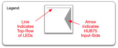
First, what my panel symbol means:
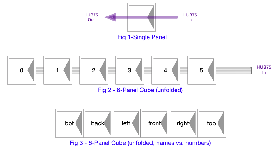
Next, how we wire the panels of our cube (shown using this symbol):
NOTE: 0 to 5 numbering comes from content ordering within the memory image of the driver.
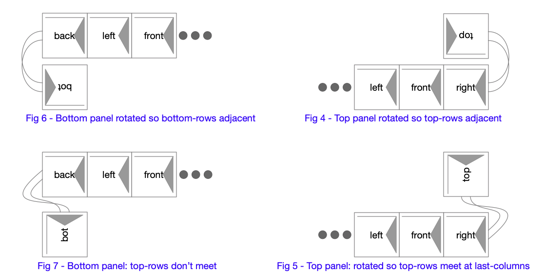
Lastly, how I see our four possible arrangements:
(NOTE: I'm running a Fig 2 or Fig 3 arrangement)
Am I correct in this thinking and what @Twyyx and @AndreasS have you decided on for your cubes?
Also, @Twyyx and @AndreasS would you please let me know if the panel side names as shown in Fig 3 make sense (are acceptable) for your cubes. If you think of yours as different from the names shown in Fig 3 can you please indicate what names you use for the positions in the chain of panels? (as my naming is somewhat arbitrarily derived ;-)
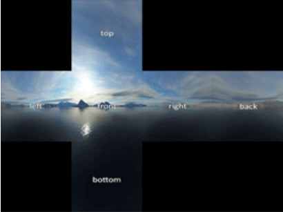
Regarding the image loader, as you can see the mechanical placement of the top and bottom panels causes rotation of the pixels assigned to those panels. If we can come to an agreement on how we will wire all of the cubes, then our loader simply needs to use a single rotation scheme for mapping the pixel values of the image to those panels. Does this also make sense?
could you please put such a picture in one of the next demos for testing?
{images omitted}
These pictures are from the other cube project.
My thoughts regarding these images.
The file containing images in the form you are showing is 12 panels in size (3 rows of 4 panels) while we are only a six-panel cube. If we choose a different arrangement of panel content within the file our smallest file size would be 2 rows of 3 panels or 3 rows of two panels. I mention this because the 24bit .bmp file format is not compressed data. Each pixel within the file is described by 3 bytes of color data. .bmp files for the flattened cube as you show would be nearly 2x the file size we need.
This means the total size of our 12-panel file, if my calculations are correct, is ~ 72kB or ~36kB for a 6-panel file.
What placement of the top and bottom panels would be best to use? I could imagine that the top panel could be in any of the locations in the top row, and the same would be true that the bottom panel could be in any of the four bottom positions. (we would want to make a placement decision so we don't have to decode many different possible placements.)
I'm not against this if this group wants to use this format. I'm simply observing the issues so we can make a decision with implications in mind. ;-)
However, I am aware that this is merely the initial guess on what works best for keeping things simple. If there is something that simplifies mapping and buffering, I think that should supersede the rules above.
Related:
The direct rendering API I've been thinking about would allow for an "tween" phase of remapping. In other words, if we had a set of discrete video buffers in hub ram according to sum agreed color packing or layout, it should be possible to add a couple re-indexing functions in the middle to allow the physical orientation of panels to be adjusted with config or even dynamically. This added layer wouldn't allow it to run at the same frame rate, of course. I think some configuration values which point to the offset in hub ram for each panel, as well as determine the pixel streaming pattern might be easier and more efficient. (It would basically dispatch to a different tight loop in each possible case)
This is hand-wavey, as I'm still not caught up on the power bus yet. I have large heat sinks, thermal compound, and planar resistors on the table now.


Comments
NEWS
v0.9.0 of the LED Matrix driver has been released. This allows us to now correctly drive all 6 panels of our P2 P2 Cubes.
Download from the P2 Obex or from my releases page
Please let me know if you find something that would be useful to have in our driver by filing an Issue at my Repo
See my test results at my Cube Testing Page
See measured performance numbers here
Enjoy!
Hello everyone,
I was able to repair my defective 6th panel (it was the upper one for me).
I re-soldered some components with flux (no clean) and now it's 98% ok.
@"Stephen Moraco"
The "demo MultiPanel" is very cool. Now I have something to play with again. In one view they are all numbered P0-P5 and in the other view they are labeled Front, Left, Right, Back and Top, Bottom. Great! Is there already a scroll command in the driver to make the font run vertically?
Is it also possible to distribute a picture over all 6 panels. If so, it could be in a future demo.
Many Thanks,
I'm looking forward to the next driver version
Best regards
Andreas
Is any one still working on there cube? I just started to begin working on mine to see just if I can build too as well.")
If you have any questions we will help you here. Twyyx will definitely bring out updates for the cube, this is still a prototype. I also run mine with a power supply to test it, but will soon try it with rechargeable batteries.
@"Stephen Moraco"
could you please put such a picture in one of the next demos for testing?

These pictures are from the other cube project.
@Twyyx
do you maybe still have the 3d model of the pcb_liner there? I would like to adapt this to my board and print it from tpu.
Have already adapted the holes to my panel. Have found a program to edit for stl files.
Thanks
Great to here and thank you for welcoming me along. So far in my prototype model I been trying to construct a stable reliable brackets that can keep cube it all together in place along with slots for electronic boards battery and wires which I don't want to over think on it right now because by having a very compact space makes my imagination limited for now. I came a cross old Nintendo Game cube refabricate some of the parts and create brackets that can keep 5 of the panels together without losing too much space and hopeful soon will be ready for meat and potatoes.
Another source of inspiration, and maybe someone we should reach out to:
https://tomverbeure.github.io/2021/05/16/Pixel-Purse-LED-Cube.html
I do have plans to release updates and more docs from the prototyping phase. It's really nice to see others jumping in and pushing on the idea together.
Once I get back into the workshop, I can make more progress. Sometimes life happens while you're planning other things!
Wow super impressive! Puts my cappy effort to shame!")
Good evening,
is it allowed to adapt the 3D models (stl) by "Bob Miller kbob "to other panels and then to post them here?
Do I have to ask him for permission before?
If so, how? I can't find a button / link on Github to write to him.
I like its structure and I would then like to test adaptations.
greeting
Andreas
Andreas,
I've found Bob's contact info and reached out to him. I'll let you know if he responds, even if he doesn't join us here.
Hello, World!
Thanks for letting me know about this group, Twyyx. I haven't read this thread yet, but I'm excited to see more cubists.
AndreasS, you're welcome to use my STLs any way you want. I can also provide the Fusion 360 files, if you happen to use F360. (You can also export to other CAD formats.)
Edit: the F360 files are already in my Github repository. I forgot -- haven't really touched this project in the last two years.
Bob
Hi,
kbob
thank you for using your templates
&
twyyx
thanks for the request.
I'll shorten the data cable to about 2 cm.
my panels fit now
&
i adjusted the holes for the magnets to the round ones.
Next I want to adapt the bracket to the P2 & Eval HUB75 & the battery
Andreas
Looking for Help
Do we have anyone with a bit of time and experience with image manipulation and video conversion?
I'm reasonably good with working the direct hardware control and I have more work to do with enabling various kinds of panels to work with our driver.
I would like to invite someone to help us who can contribute a layer of image processing and maybe even video frame conversion to show more on our panels.
I'll work with the person joining us to provide any driver support you need to help in doing this.
I've already provided example handling of bmp24 bit image conversion to panel display (example in driver demos). I've already provided panel-set pixel setting at row, column, and panel specific (single panel within panel-set) pixel setting at row, column.
There is an image request earlier in this thread. I can envision that the activities would be:
I'm hoping we can welcome a person, with this kind of experience to draw on, to come and play with us on this cube project!
AndreasS that frame looks both very familiar and strangely different. Are you holding all six sides on with magnets? The screws were a pain to use.
Will the Propeller generate graphics standalone, or will it connect to a host of some sort?
And what did you end up doing for a power supply? I designed my own board*, as I couldn't find anything off the shelf that fit and generated enough current. Calculations showed that it would want 24 amps @ 5V, but it ended up being closer to 18 @ 4V.
*I designed a board, then an experienced EE took pity on me and re-laid it out much better.
Also, I expected a lot of heat inside the box, and planned to use HTPLA to handle the temperatures. But it isn't hot at all. The temp. sensors on the Raspberry Pi read maybe 5℃ warmer than they would in free air. I guess running the LEDs at 4V had a lot to do with that.
Hello Kbob,
ok i then print 5 panels holder/frame and the new skeleton with holes for the magnets. I don't know how the connection to the propeller board will be made later, maybe Twyyx and Stephen Moraco can say something about it. Can we use your power board? If so, could you recommend a circuit board and compile a parts list for the parts?
You can use the power board. I got my PCBs from LCSC. I used 2 oz. outer copper layers for high current. It has components on both sides. I populated one side with a stencil and reflow oven, then hand soldered the other side. The heavy copper layers made hand soldering slow.
The board has two power supplies. It's a 25 amp 4 volt supply for the LEDs, and a separate 5 volt, 3 amp supply for the Raspberry Pi and FPGA board. You can probably replace the CPU supply with something much lower current, as the TI chip I used (LMZ14203) is expensive.
The board also has soft power circuitry for a Raspberry Pi that you don't care about, An IMU, and a battery meter (ADC), both connected via I2C. I never got around to using the IMU or meter.
So I guess the power board is more of a guideline than a drop-in solution for you. (-:
The BOM is in my Github repository.
I have some comments about my mechanical design.
The hinged lid and magnetic clasps work very well. The magnets are removable so you can print many iterations of the plastic, and move the magnets to the new versions. The hinges work well, are simple, and don't take much interior space. The way the hinges attach to the lid is the best I could do with 3D printed parts. It's an extra assembly step, but it works and has been reliable.
The tool free assembly for the circuit boards and battery work pretty well. Things are very tight, and there are a lot of wires, but that's more or less unavoidable. You'll be a little better off since you have a single CPU board (maybe?) instead of a Raspberry Pi plus FPGA board plus HUB75 board.
I made a "clip" to hold the Raspberry Pi's connector in place. I shouldn't have bothered -- the friction in the connector is stronger than the clip.
We talked about making a Pi Hat that would incorporate the FPGA and one to three HUB75 connectors, but that didn't happen. It would have freed up some space inside, though.
You probably figured out that the Raspberry Pi holder, power board holder, and battery holder each have leaf springs in their plastic so that you can just bend the springs to insert/remove the components. When I took it apart and put it together many times, the plastic springs got weak and eventually I had to replace those components. I took it to a trade show where people did exactly that for two days. I reprinted those parts.
I have extra batteries and extra battery holders. I can swap out a battery in just a few seconds.
The "skeleton" design -- a frame that goes around the edges of the cube and has attachment points. I have mixed feelings about it. As I mentioned, it is a real pain to fit nylon locknuts onto all the internal screws when attaching the panels. The beveled LED panel frames are time consuming to put on and off, and they are too specific to the exact model of LED panel that I used. And the 3D model is complex, as you know if you've opened it in Fusion 360. So assembling the skeleton, frames and hinges is very slow, but installing the electronics and wiring is very fast.
If I did it again, I think I'd just have the frame go around the perimeter of the LED panel. The internal ribs don't add anything. (They were used in early versions of the design, but became useless.) The way the lid hinges attach do use the ribs there, so those ribs would have to stay.
The screws are captive between the frames and the LED panels. I did it that way so that overtightening a screw couldn't force it into the LED PCB. Seemed like a good idea at the time...
But for a 3D printed chassis, I think it's the right idea. I've seen (photos only) other designs for P2.5 LED panels that use laser cut plywood frames, and those look simpler and easier to assemble. But the P2.5 panels are much bigger (twice the internal volume), so there are fewer constraints.
I don't know anything about the Propeller (sorry!) but I thought the Raspberry Pi and FPGA combo worked pretty well. The Pi has network connectivity, a development environment, good I/O, and a GPU for those graphics that can use it. I used a Pi 3 instead of a Pi Zero, as I thought four CPU cores would make animation smoother than a single core. (No idea whether I was right, but the Shaderboy renderer does use four threads and the GPU.) The FPGA has rock solid timing to drive the HUB75 signals. I know Greg Davill has made some LED cubes using Cortex-M micro controllers, so you can certainly get by with less compute power.
I made all my own cables, and I made each one to exactly the needed length. The ribbon cables were fast and easy. I hand crimped the others. The power cables were not too bad. The Raspberry Pi power + data cable was the worst, 10 conductors in a 2mm pitch connector.
Thanks for giving me an excuse to remember all the fun I had making this project.
I've started work on "position of cube determination"
I'm working on an object for the Click "MPU 9DOF" module. This has 3-axis values (x,y,z) for Accelerometer, Gyroscope, and Magnetometer.
Status
Up next
--> What else would we want to know about the cube position? Please let me know!
If you have an interest you can follow my current progress as my work is routinely committed to my project repository: P2-click-MPU-9dof
My intent is to publish this object to the P2 Obex as soon as it is working enough to be useful.
Hello everybody,
can someone tell me whether such a power conditioning is absolutely necessary or can I connect the 2 LiPo batteries directly, in parallel with the 5v step-down regulators?
I would very much NOT do that - the "5V" step-downs are never going to be perfectly 5V. One might be 5.001V and the other 4.999V.
Now, that may not sound like much difference, but if the wiring between them is 0.001 ohms (not unreasonable for thick stranded copper) you're going to be throwing away TWO AMPS of current as heat - and sooner or later one of them's going to fail, closely followed by the other one.
Don't do that. S.
OK thank you for the info. I didn't know that. What if I connected three panels to each battery? I do not know whether the lipos are undercharged and thus break or, in the worst case, start to burn.
Hello, everyone.
Nothing has changed with electronics and software?
I still need support.
Hope you have time to take this project forward again soon.
Thank you best regards
Andreas
@AndreasS said:
I'm still working, albeit slowly on a couple of things:
What kind of support are you wanting?
Hello,
I have no idea how the cube will work later with the 2 batteries.
I would like to construct the frame as suggested by "kbob".
All frames with magnets, but I don't know how we can then stow all components in the cube.
And does the board get WiFi or Bluetooth support so that you can later send pictures or videos to the cube?
So far I am not able to play my own picture or video on the "Propeller 2 Evaluation Board" & cube.
I know that it will take some time until the cube is ready for use,
but i would like to see a few steps forward.
Unfortunately I cannot serve with software knowledge.
Thank you for your efforts so far.
Greetings Andreas
@AndreasS
I want to see more progress too. I need more workshop space, and have been waiting for renovations to happen. It still hasn't happened yet. Maybe next week they'll finally start. I have been building up my workshop tooling, but it got to a point where I simply didn't have enough of a functioning workspace to tame all the tools and components. I'm going to start trying to be more active here on the weekends with updates even if I have to juggle a bit.
The next step from me will be power supply testing; verifying how long a 7.4V LiPo pack will work with the 5V DC/DC converter before dropping out under load.
I have a vacuum chamber now to test stabilizing panels with UV resistant clear resin. This might go badly! But, it might go well too! So that is thing 2 on my list.
I'll post my results as soon as I have something.
While reasoning thru how we would make an image loader routine for our cube I realized that we likely need to agree on a wiring convention if a single loader is going to work. Would you please check my reasoning? It seems to me that if we are guided strictly by the shortest cable paths between panels then it also seems to me that we have four possible panel arrangements for our cube. The top and bottom panels have two possible positions which meet our shortest cable requirement. If we are to have a loader we need to decide to use an arrangement we can all agree on.
Here's my reasoning in graphical form:
First, what my panel symbol means:
Next, how we wire the panels of our cube (shown using this symbol):
NOTE: 0 to 5 numbering comes from content ordering within the memory image of the driver.
Lastly, how I see our four possible arrangements:
(NOTE: I'm running a Fig 2 or Fig 3 arrangement)
Am I correct in this thinking and what @Twyyx and @AndreasS have you decided on for your cubes?
Also, @Twyyx and @AndreasS would you please let me know if the panel side names as shown in Fig 3 make sense (are acceptable) for your cubes. If you think of yours as different from the names shown in Fig 3 can you please indicate what names you use for the positions in the chain of panels? (as my naming is somewhat arbitrarily derived ;-)
Regarding the image loader, as you can see the mechanical placement of the top and bottom panels causes rotation of the pixels assigned to those panels. If we can come to an agreement on how we will wire all of the cubes, then our loader simply needs to use a single rotation scheme for mapping the pixel values of the image to those panels. Does this also make sense?
My thoughts regarding these images.
I'm not against this if this group wants to use this format. I'm simply observing the issues so we can make a decision with implications in mind. ;-)
@"Stephen Moraco"
I have a proposed scheme for this based on a couple simplification principles:
1) The bottom panel rotates "up" to the first side panel.
2) The fourth side panel rotates "up" to the top.
This is described under https://github.com/jshook/p2_p2_cube/blob/master/3d_models/assembly.md#03-assemble-the-joints
However, I am aware that this is merely the initial guess on what works best for keeping things simple. If there is something that simplifies mapping and buffering, I think that should supersede the rules above.
Related:
The direct rendering API I've been thinking about would allow for an "tween" phase of remapping. In other words, if we had a set of discrete video buffers in hub ram according to sum agreed color packing or layout, it should be possible to add a couple re-indexing functions in the middle to allow the physical orientation of panels to be adjusted with config or even dynamically. This added layer wouldn't allow it to run at the same frame rate, of course. I think some configuration values which point to the offset in hub ram for each panel, as well as determine the pixel streaming pattern might be easier and more efficient. (It would basically dispatch to a different tight loop in each possible case)
This is hand-wavey, as I'm still not caught up on the power bus yet. I have large heat sinks, thermal compound, and planar resistors on the table now.