

Phase shift keying and Goertzel
 ManAtWork
Posts: 2,367
ManAtWork
Posts: 2,367
To reduce the number of required pins on expensive industrial connectors I'd like to use only one pin pair for the power supply of a "smart sensor" and its data transmission. This should work with simple passive low- and high-pass filters as the supply current is DC and for data transmission something in the MHz range could be used.
I think, the Goertzel feature of the P2 could be used so no external modulation/de-modulation chips should be required. I need at least 1MBd bandwidth. So I'd use something in the 10..20MHz range as carrier. This keeps the filter components small and should not cause too much aliasing and EMI problems.
My idea is to use binary phase shift keying (BPSK). The sender encodes 0 bits as a 0° phase signal and 1 bits as 180°. The receiver uses the Goertzel streamer mode to decode the signal. Lets assume sender and receiver are perfectly synchronized at the beginning. This would result in two spots in the phase diagram with the amplitude (radius) depending on line length and damping.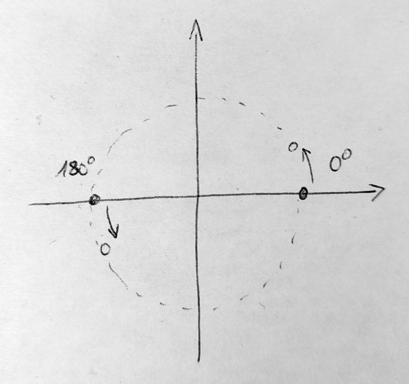
As the two clocks of sender and receiver have tolerances the two spots for 0/1-bits will start to move and rotate over time. This can be compensated by calculating the angle of the delta vector with QVECTOR and rotating all future inputs in the reverse direction.
Or can anybody think of a better method? Quadrature phase shift keying allows to transmit two bits per time slice but is a bit more sensitive to noise. For example, using a 10MHz carrier and 1MBd data rate BPSK needs to switch phase every 10 periods and QPSK every 20 periods. The latter would allow for more time to accumulate the Goertzel result and more instructions for the software loop. But synchronization is a bit more complicated, I think.
Comments
To couple the signal to the supply line I'd use a standard common mode choke and turn it into a differential mode choke by swapping two pins.
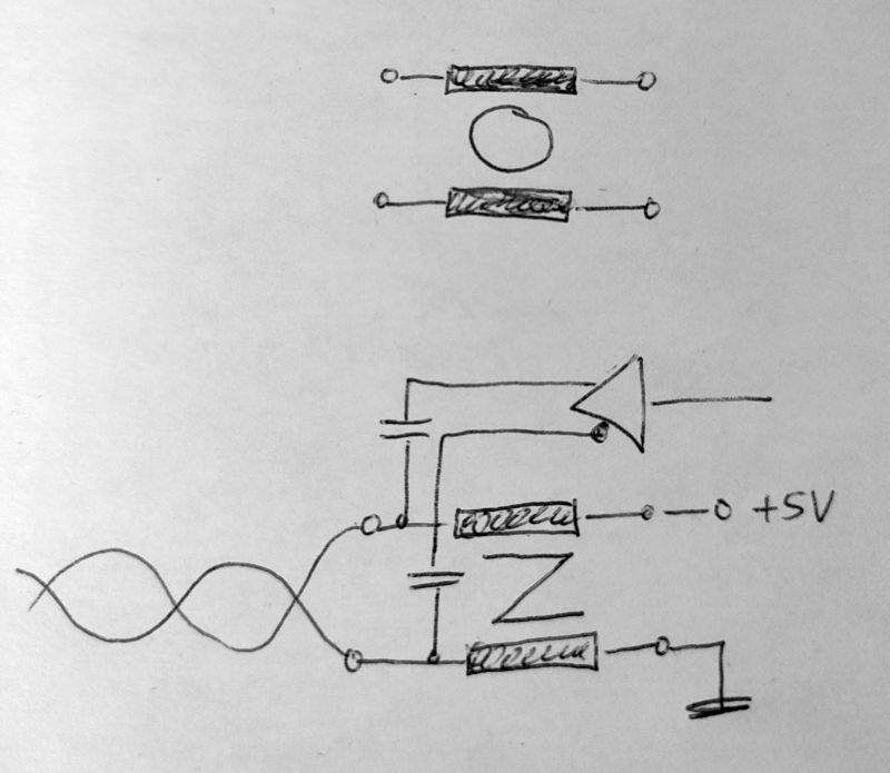
Two capacitors can be used to connect the transmitter/receiver pins. I have to check how robust this simple setup is against EMI peaks. If twisted pair cable is used there shouldn't be much energy in differential mode. But ground loops or electrostatic discharges coukld cause strong comon mode peaks. Maybe series resistors and clamping diodes are neccessary for protection of the P2 pins.
Or is the BPSK or QPSK just overkill and sending baseband RS485 data would also work? Maybe, if some RLL code is used to keep the DC component of the data stream to a minimum.
I'd probably do OOK (on/off keying, basically super simple AM) with the circuit you've described. If your sensors had power and data over an sma or bnc, you could do single-ended "rf" with a single inductor and capacitor. For concern over induced current, wrap a ferrite around the cable.
Just re-read the bit about pin usage on industrial connectors. Honestly, single-ended power/data is probably still fine. For 1MBd, 10mhz is probably plenty. You might be able to get away with 5mhz.
If you want to reduce frequencies used, you might actually be able to get away with something like 256qam which would get you 1mbd over a 125khz carrier.
Haha, no. It's a bit more tricky. My "sensor" is actually an encoder with some additional features (memory for "digital motor nameplate", overheat warning). Many servo motors have this type of connectors:
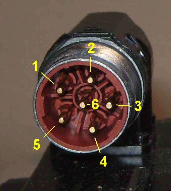
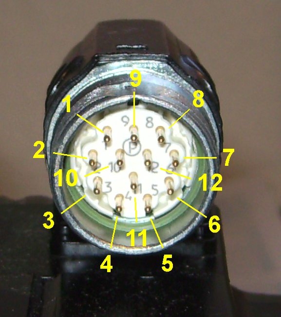
4 pins are for motor windings and ground. The remaining 2 are sometimes used for an NTC thermo sensor, sometimes just unused. Then there is an extra connector for the encoder or resolver like this:
If I use only one connector and take the two spare pins for encoder power and data communication I'll not only save the money for the connector, I'll also save my customer a lot of work for routing cables.
The problem is the motor windings are powered with a 300+V PWM signal with 20kHz and slopes as high as several kV/µs. The wire pair for communication is twisted and shielded but it runs through the same cable and connectors so some noise will be unavoidable.
A single spike can ruin an AM signal. FM or PSK are much more robust against interference.
You could use an error-correcting code, such as Hamming.
-Phil
Yes, if only few bits are affected, Hamming is good. If there are bursts that affect many consecutive bits then an XOR block strategy would be better. (Adding a third block made from the XOR of the first and second half of the data plus three checksums. If one block is invalid it can be reconstructed by calculating the XOR of the other two valid ones)
To take advantage of the twisted pair cable a differential signal is obligatory. Single ended transmission is inferior and has not much chances to work reliably.
No matter what encoding and modulation is used, narrow bandwidth (high selectivity in the receiver) and good separation/distance between carrier and disturbing frequencies result in better SNR. High selectivity normally means expensive filters in the analogue world. But I think the correlation scheme of the Goertzel mode should excellent selectivity at no cost (well... if the P2 is already there, anyway).
OOK or QAM might work with a low-if transciever. https://en.m.wikipedia.org/wiki/Low_IF_receiver
If quadrature i/o from the Propeller were mixed with 10MHz, you could have your signal at 10.7MHz availing many off the shelf SAW filters to reject the hv drive signal.
I'd need to do a bit more research into if mixers to find something appropriate. I'd start with the schematic of the Great Scott Gadgets HackRF one.
It's important to note here that the interference is not white noise. It's highly harmonic. It would be bad if those harmonics coincided with the carrier frequency. Although from the time-domain perspective, it should be possible to transmit lots of bits between motor PWM transitions. Many communication systems interleave the data to help the error correction be more effective against busts of errors.
The P2 ADC starts to loose SNR significantly past 5 MHz. There is also a chance that your chosen carrier frequency is near one of the ADC's oscillations.
@Circuitsoft: Yes, you could do it the classic way and use an external HF transmitter and receiver. But the idea was to avoid that by the use of the Goertzel unit.
Yes, as the motor PWM comes from my own servo driver the frequency is well known and it should be easy to select a carrier frequency that does not match with one of the harmonics.
That should also be possible. Maybe we could just repeat the data packet several times at a much higher baud rate and then throw away the bad packets and hopefully still have at least one that survived.
Interesting... Can you please explain a bit further what that diagram shows? It's all well above 50dB. 10 to 20dB SNR should be sufficient to get reliable data transmission.
I also think that the exact number for the carrier frequency doesn't matter much as long as it's not a harmonic of the PWM frequency. The way the Goertzel accumulation works it's just a matter of sequence of the weighting factors in the sine table. It doesn't matter if more periods of a higher frequency are sampled and summed up or less periods of a lower frequency. So I don't think there is a 5MHz limit. The carrier just has to be an order of magnitude lower than the system clock so we get enough sample bits per carrier period.
Near Field Communication(NFC) does send 106 up to 848 kbits/s over a 13,56 MHz Carrier (AM). If the propeller could do it, some nice experiments could be made:D
Sending AM is easy. Yust configure a smart pin to be the logical AND of two other pins, TXD from a serial transmit smart pin and a 13.56 MHz NCO pin. Receiving and decoding is a bit trickier. Goertzel is hard to use if the bit timing is not well synchronized because of high frequency tolerances of sender vs. receiver. You need to oversample and guess the exact location of the edges between the bits.
Sorry for being slightly offtopic about NFC.
Oh, that would create a lot of harmonics. I think it should be possible to lay down two sets of sinewaves in the RAM, one being a sine with 100% amplitude, one with 90% amplitude (the off-key) and then have the streamer alternate between those, putting out a neat sinewave. The PLL/Streamer DAC would be set to 16x the carrier frequency maybe.
Well, NFC has one master and the slaves are riding on the wave by simply switching a parallel resistor on and off to weaken the field. (the antennas are inductively coupled)
Thus the Sender/Receiver are in sync.
The question is if the ADC of the propeller can work up to 13.56 Mhz and if there are any bits of resolution left;) If there were maybe 4 or 5 Bits left, could the goerzel make any use of it?
Ok, I'm no expert for NFC. I thought as its "near field" and low power harmonics would not be too critical and a square wave + low pass filter would be OK. Of course, sine wave and DAC/streamer is better.
Please read the docs how Goertzel works. There is no such thing as "bits of resolution" in Goertzel mode, at least it's not the same as in normal ADC modes. Instead, single bits are sampled and weighted (multiplied) with the coefficient from the table. Everything is summed up until a given number of perods have passed. So it's some sort of correlation filter and averaging taking place all at the same time.
Even if the carrier is, say, 20MHz and you only have 10 sampled bits per period at 200MHz sysclock you can improve the resolution by summing up more than one period. One bit at 106kBd and 13.56MHz carrier is 128 periods of the carrier frequency. That means 1888 sampled bits or >11 ENOBs in SINC2 mode.
Hmm, I tried to work a little bit on the actual implementation. I thought the sender was easy and just the receiver is a bit tricky. But it's not all that easy to tell the streamer to shift the phase of the DDS output. There is no way to modify or even read the current NCO phase. As I understand the docs the normal command scheduling with XCONT and XZERO also doesn't work in Goertzel mode because the streamer always runs continously. D[15..0] doesn't specify the number of NCO cycles the command runs but the number of cycles used for accumulating.
So the only way to do controlled phase shifts that comes to my mind is to have multiple sine tables in the LUT and switch from one to another. The docs also are vague about if XCONT is executed a) immediately or b) at the next NCO rollover or c) at the final rollover completing accumulation in Goertzel mode. c) would be best because the number of cycles used for accumulation could be adjusted to the bit rate and the commands for the next bit could be pipelined. But I have to find out if this actually works or if the bits have to be timed manually with waitx/waitctx.
You could still use the Goertzel mode with an LT5560 and a 10MHz oscillator, and a single pin. Two pins (t/r switch) and two mixers for bidirectional communications. Again, a ceramic filter aimed at FM radio IF would be pretty effective on the input/output here.
Arrrgg. Bad/missing documentation. I've tried it out and it seems that XCONT waits if the command buffer is already full. Sounds logical but is not documented. So the "final rollover" in Goertzel mode is the moment the accumulation cycles are completed even if the streamer continues to run.
I've also found that there is mechanism to set the phase. It's the TTT bits in the source field of the XCONT command. They are added to the LUT address with rollover so that the AAA bits are left unchanged. This is documented but you won't find it if you search for "phase".
Do you want to shape/filter the psk output?
https://en.wikipedia.org/wiki/PSK31#/media/File:Bpsk31bits.png
Assuming the carrier frequency is an integer fraction of the sample rate, this could be done by assembling pieces of pre-calculated waves together. There could be 4 pieces: 0-0, 180-180, 0-180, 180-0 degrees.
Another possibility is to use the chroma modulator to generate the signal.
The receiver might need to oversample the signal in order to lock onto the bit timing.
I agree taht the filtered waveform looks a lot nicer than hard switching the phase. This would surely be required in a true HF transmission over antennas to avoid sideband pollution. But as I have only one channel over a dedicated cable and I'd like to keep the external component count low I won't filter the output. The cable capacitance and the Goertzel unit in the receiver does enough filtering.
Yes, I already thought about that. I'll start testing with 10MHz carrier and 2µs sampling rate per 2 bits (QPSK). If I use a 8-bit sequence (00_00_10_10= 4 samples) for synchonisation I get this at the receiver side:
By examining the "interpolated" position of the mixed bit I should be able to recover the sync info (how much delay is required for perfect sample vs. bit timing). The amplitude and phase angle of the two full/opposite dbits can be used to calibrate the phase offset and amplitude threshold.
With oversampling I wouldn't have to waste 4 samples = 8 bits and maybe a single start-sample (2 bits) would be enough. But the danger of false start bits caused by bursts of switching noise is higher. If higher samples rates are possible I#ll rather use this to increase the data rate. 20MHz and 1µs or even 0.5µs (=4MBd) should be possible but I don't know if 100 clocks = 50 instructions are enough for the software to decode the bits.
Good idea. I'll try to use Goertzel DDS, first. Now that I begin to understand Chip's documentation and figure together myself what's missing I see good chanced that it's possible. If not I can still try the alternatives.
Phase shift using the TTT bits works very well. So the sender should be no problem.
I've found out that XCONT causes a little phase jitter of the bit sampling window vs. the carrier phase while XZERO causes a small frequency error if the NCO divider ratio is no power of two.
I think Chip had said that that is a Sinc2 filter. It gets applied on top of the smartpin's scope mode filter. The smartpin scope filters provide 4 to 6 bits of resolution, and the Sinc2 will add to that. There will be a calculable resolution. However, the maths is somewhat over my head so I've not investigated it.
It should be clean as long as sysclock frequency is a whole multiple of the target frequency. Video has a slight pixel-crawl in same situations. It's the nature of relying on a NCO for programmable frequencies.
EDIT: Adjusting the sysclock's PLL to suit would provide a clean solution.
It doesn't look too bad. Ideally, there should be a square with spots only near the corners. But as the synchonisation doesn't work, yet, the bits get "blended" with the previous or next one.
Ok, I didn't know that Goertzel and scope mode are linked together as this is mentioned nowhere in the docs. But even if a single sample is limited to 6 bits the averaging over multiple periods of the carrier should help improving the resolution.
200MHz/10MHz is a whole multiple but 2^32/10 leaves a remainder, so the NCO counter is creeping.
That's no option because that would affect all other baud rates. But I've found out that XZERO doesn't work at all and the jitter of XCONT is so small is doesn't hurt.
I have to implement a re-synchronisation every 8 or 16 bits to compensate the frequency tolerances as soon as the sender and receiver run from a different crystal in different locations. For now, they are two cogs in the same P2. Small adjustments can be made by adding a phase offset and a small increment/decrement to the NCO frequency value.
Oops, I'm wrong. Looking at the Goertzel docs I just found there is a scope mode right in front of it in the Streamer docs. Looks like that is what's intended to be paired up with the same smartpin mode.
Me actually reading the Goertzel docs now - It does clearly state the raw PDM bitstream is used:
It is a Sinc2 ( optionally Sinc1 too) filter though. So I got that part right at least.
The real barrier is it takes milliseconds for the PLL to settle. I wasn't thinking of regularly adjusting it. Needless to say, I haven't tried to understand any of what you're doing.
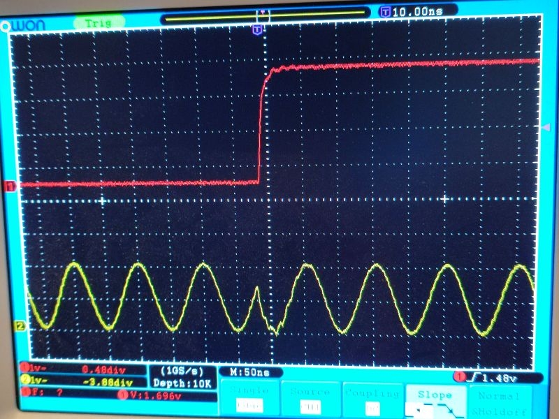
I've got the synchronisation working, now.
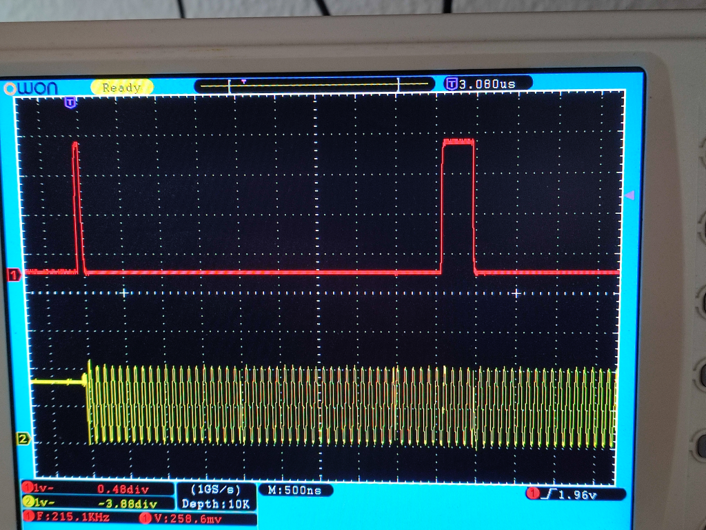
The red trace is a debug signal. The first pulse indicates that the sender starts transmitting. The green trace is the carrier signal. The second pulse of the red trace starts when the synchronisation calculations are finished and ends when the synchronisation delay is over. A bit pair time slice is two raster squares long. You can see the phase shifts after 2, 4 and 5 time slices (4,8 and 10 raster lines). So the delay starts in the middle of the time slice after the start bit sequence and ends exacly at the start of the first real data bit pair.
The result is a nice square in thy XY diagram. The most significant two bits of the angle result from the qvector command (= quadrant number) can be directly rotated into the RX shift register.
For now, sender and receiver run in two cogs of the same P2 chip. The next thing I have to implement ist the automatic NCO adjustment to compensate any frequency drift so that sender and receiver can run from different crystals.
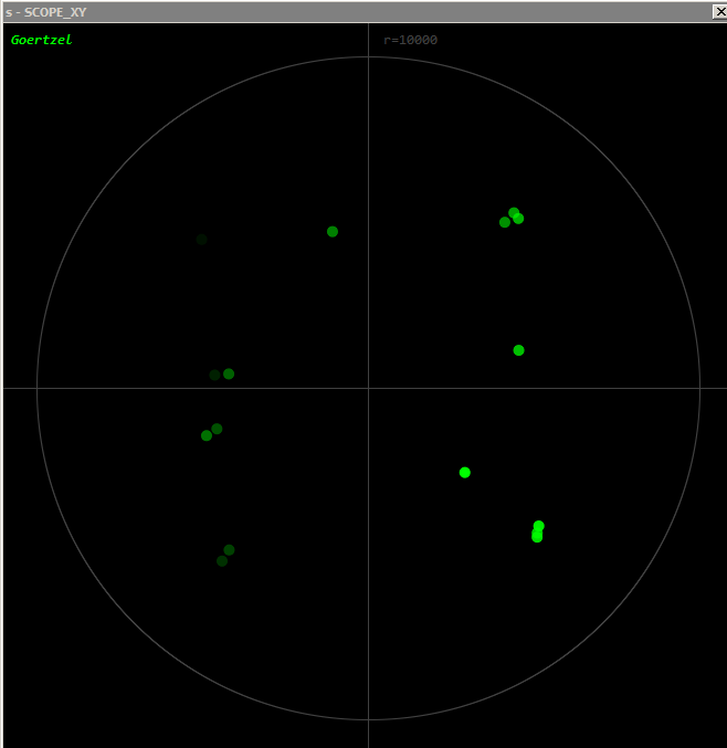
Yippeee!") NCO tracking (auto-adjustment) to the sender frequency is also working.
NCO tracking (auto-adjustment) to the sender frequency is also working.
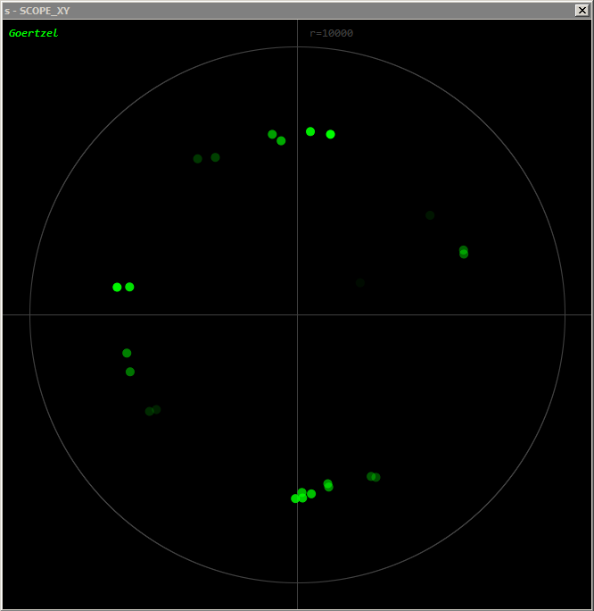
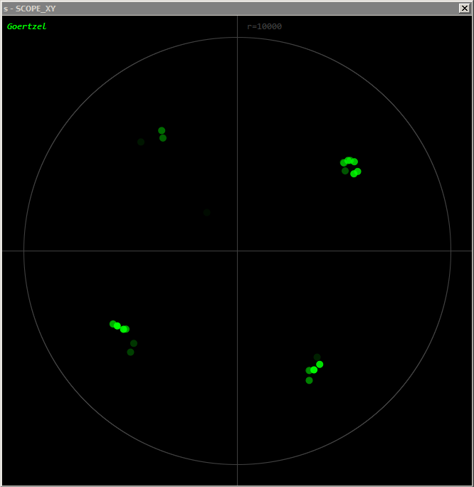
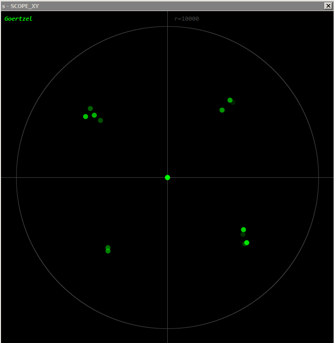
The first diagram shows the phase of the bit pair codes without NCO tracking. I've intentionally set the frquency of the sender to 10MHz + 6kHz (600ppm off). You can see that the dots are rotating clockwise (darker dots are older). After the 4th or 5th transmitted byte the data gets corrupted as the dots cross the quadrant borders. In the second diagram the phase and frequency is adjusted automatically and all dots stay in the correct quadrant.
I calculate the average angle of four samples (8 bits) while ignoring the upper two bits which represent the quadrant number or the "whole part" of the data content. The average of the lower bits represent the fractional part and can be used to detect phase error. If the average angle drifts away from the ideal 45°, 135°, 225° and 315° positions the difference is used to correct phase and frequency for the next byte. This works similar to a PLL.
A byte takes 4µs to transmit so 600ppm clock deviation causes a phase shift of ~9° per byte. Depending on the noise level the tracking algorithm can compensate up to approx. 1000ppm or 0.1% before it fails. This is far more than any crystal tolerance to be expected.
Sounds cool.
The XY graph is working well for you too. BTW: Does amplitude of the graph have much meaning at this stage?
Amlitude starts to get important in real world conditions with cable and damping. At the moment I have connected inputs and outputs directly with short jumper wires. The DACs drive 2Vpp with 75R impedance. The ADC inputs are set to 1X mode. With a real cable and the signals coupled with capacitors and some filtering I expect the receiver signal to drop to half the level (1Vpp) best case and around 1/4 with a long cable (worst case). Hopefully, I won't have to use auto-gain adjustment and can use ADC_3X mode in all cases.
I noticed some problems with the first sample after synchonisation. The phase angle is correct but the amplitude is sometimes lower and sometimes higher than normal. I suspect that the Goertzel accumulator does not get cleared properly if the number of XCONT and GETXACC commands don't match. I tried inserting dummy GETXACCs but it didn't help. I have to ask Chip about that.
The next step is the design of the hardware. The basic circuit has already been shown in post #2. I plan to avoid external drivers or amplifiers alltogether and only use passive components. An unidirectional transmission line is relatively easy. We could use only the common mode chocke and coupling capacitors in the picture of post #2 and add some resistors and transzorb diodes for protection.
However a bidirectional line is not that easy. We need termination resistors on both ends so by driving two 75R loads with the 75R DAC impedance we already have the signal level drop to 1/3. I think I'll spend two separate pin pairs for the sender and the receiver. The sender could be used as termination for the receiver side by simply driving a constant 1.65V DC level with the 75R DACs. And I'll add a parallel resonant LC tank as filter on the receiver side that shorts all low and high frequency out-of-band signals for better noise immunity.
The Goertzel algorithm should provide good selectivity by itself as long as the input signal stays in the valid range of the ADC. However, at higher gain modes short but high energy spikes can saturate the input and it takes a while to recover from that. The current sources of the ADC pins have to discharge the input node back to the VCC/2 level to bring the sigma delta feedback loop out of saturation.
Maybe, active termination with some sort of soft-clipping would be better than passive, resitive termination. I have to do some experiments with different cable lengths. While QPSK should be relatively immune against noise ringing due to reflected waves could become a problem. 10MHz has a wavelength of 30m so a 7.5m cable can already form a 1/4 wave resonator.