

induction heating
 ManAtWork
Posts: 2,358
ManAtWork
Posts: 2,358
I'm trying to build a selective soldering machine. The difficult parts, CNC kinematics and liquid tin pump, are alredy solved. However, the seemingly easy part, heating the tin to melt it, is not so easy as it first seems. Lead free soldering tin dissolves even stainless steel relatively quickly and I didn't want to machine the whole pot from titanium. So I decided to use an enamel coated pot and heated it with a standard electrical hotplate.
This works basically but the temperature of the tin is difficult to control. Because of the large thermal inertia of the cast iron hotplate the temperature tends to overshot a lot if a simple on/off thermostat is used. A PID control is difficult to tune. So I decided to use an induction hotplate instead which offers instant power control. However, a standard off the shelf induction plate can't be used because you can't control the power with a simple interface but instead have to push several buttons. Safety features like pot removal detection and soft start causes delays...
But it's not very hard to build the whole power electronics for the plate from scratch. I've bought a standard induction plate from Amazon and ripped the electronics apart. This application note gives some useful information how the thing works. The coil of the plate is put together with a film capacitor (or actually two) to form a series resonant circuit which is driven by an IGBT or MOSFET half bridge.
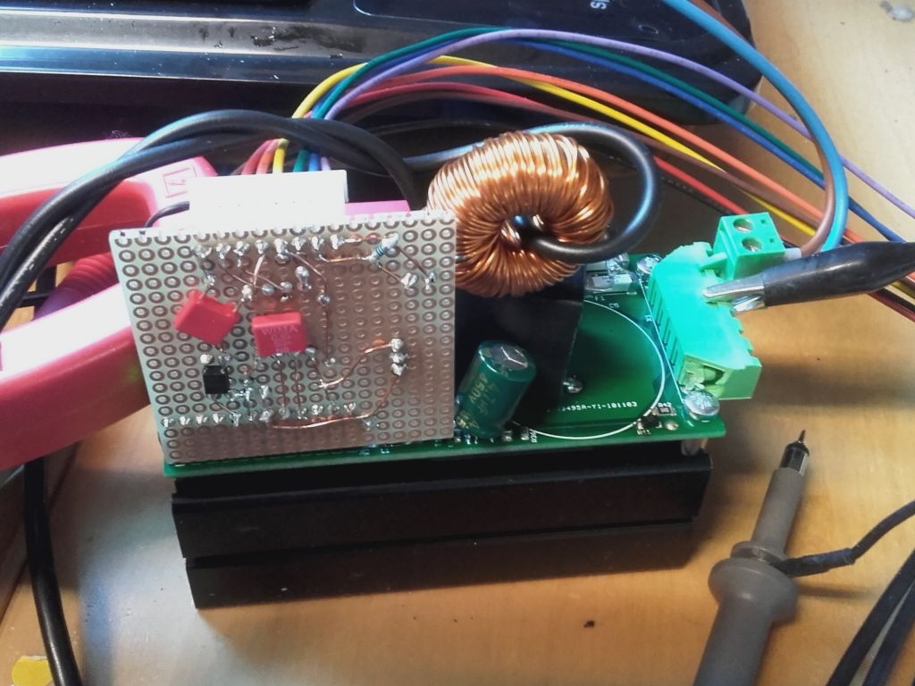
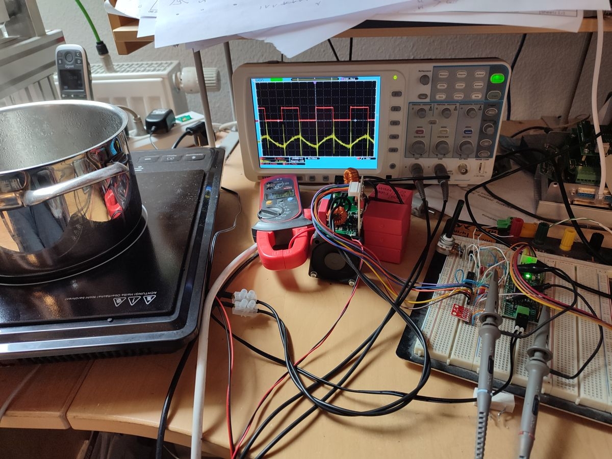
The half bridge is always driven with 50% duty cycle but variable frequency. Higher frequency (above the resonant frequency) means lower current and less power, lower frequency (closer to resonant) means more power. I recycled a servo supply PFC module I had lying around which already contained most of the required circuitry: rectifier, capacitors, half bridge and MOSFET drivers. I've added some optocouplers and a curent transformer (actually a toroid inductor plus one winding of thick stranded wire).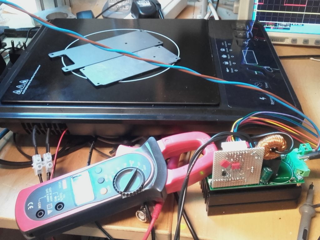
The pieces of sheet iron on the plate are used as dummy loads. A first test with a 48V SMPS was successful but I didn't dare to power it directly from mains voltage, so far.
The next thing is to get current feedback from the secondary winding of the current transformer to an ADC input of the P2. As the signal is AC coupled anyway high gain modes can be used. The transformer has a 1:167 winding ratio so 50A primary current corresponds to 0.3A secondary current or 0.3V at a 1 ohm shunt resistor.
Comments
Very cool project!
I suspect that submerging an incaloy calrod in the solder may very well be okay. I find it a bit hilarious that you found the exact same app note that I read years ago about inductive heating. I'll note, though, that the only inductive cooktop I've opened was (a) parallel resonant and (b) a class C output stage.
Sorry, what is an "incaloy calrod"? Google translator doesn't know theese words... Do you mean an immersion heater made from a coil of nickel base alloy pipe with heating wire inside?
Yes, the original electronics of the plate also used a parallel resonant circuit with only a single IGBT. But I found the series resonant version of the app note easier to understand and to control. And I don't care about $5 extra cost as the PFC module was already there.
Yes. Calrod is a trademark of ge, but has come into common use in the USA. It's the word I think of when describing a standard electric stove. Incaloy is one of several possible metals on the outside of such a heater.
I never really went through all the math to derive the function of the series vs parallel resonant circuit, and I personally find "high power" scary because of some big sparks when I was kindergarten aged...
Lastly, I would ask what stainless steels you've tried. I feel like 316 might be okay for your application where 304 isn't.
It works! Even with only 48V suply I can feel the pot heating up, well... getting warm a little bit. My clamp ampere meter reports 1.7A DC current from the supply so that's ~80W total power consumption at 20kHz PWM frequency. The P2 measures 5.5A RMS current at the coil output. The difference is because of the half bridge driving the coil only at around half the voltage and the total current ist the sum of active and reactive current.
As we can expect the power to frequency function is highly non-linear. At 25kHz power drops to 30W and current to 3A. At 30kHz it's only 15W and 2A RMS.
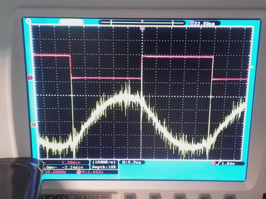
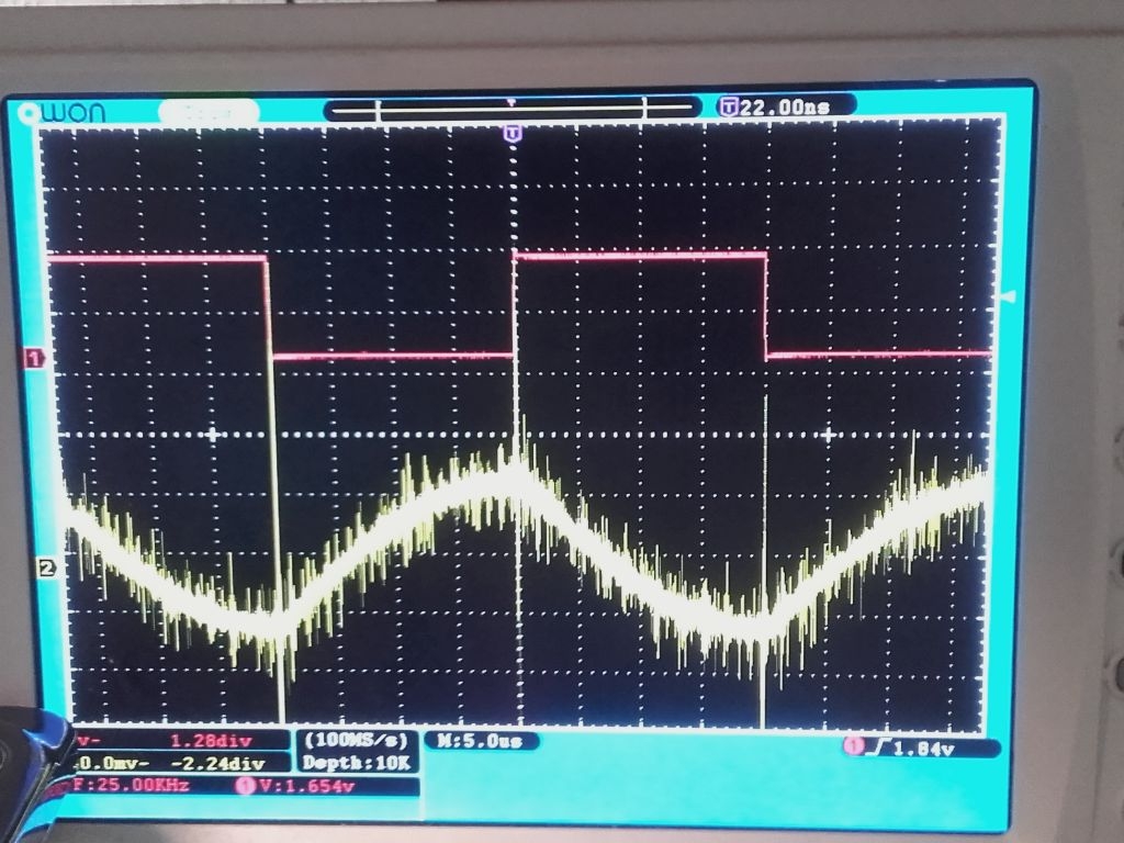
First (red) trace is the PWM/NCO output pin from the P2, second (green) trace is secondary voltage of the current transformer.
I have to implement some safety features then I'll test with full mains voltage.
It's impressive that there is almost no noise at the RMS readings while there is lots of noise visible on the scope. Only the last digit is dithering which means ~30mA noise. Unfortunatelly, it's difficult to calculate the actual output power. Phase shift between current and voltage is unknown because I can't monitor the voltage at the floating terminal of the induction coil. I also can't measure the DC input current without the help of the clamp ampere meter. But it doesn't matter much. Assuming that the power is proportional to the RMS current is only a rough guess. But the closed PID control loop with the thermocouple will balance out all errors of the power stage.
BTW, power is proportional to the square of voltage so I could expect something around 1.8kW max. at 230V. The MOSFETs are rated for 48A continous current at 20kHz which translates to ~35A RMS current at 100Hz rectified mains voltage.
Here is the test code:
'' InductionHeating.spin2 '' Test program for induction hotplate with MOSFET half bridge { current transformer ratio 1:167, 50A peak primary -> 0.3A secondary 2 ohm shunt resistor -> 0.6V peak input voltage, AC coupled ADC mode x3.16 gain, +/- 0.8V range, 12 bits resolution (signed) 2048 LSBs = 66.66A, 30.72 LSBs = 1.0A } CON _xtlfreq = 25_000_000 _clkfreq = 180_000_000 '_BAUD = 230400 ' serial debug port ' Pins pinPwm = 8 ' PWM output pinEna = 10 ' power stage enable output pinAdc = 12 ' current transformer ADC input modeAdc = P_ADC + P_ADC_3X modeSinc3 = %10_1000 ' SINC3 filtering 256 clocks modeNco = P_NCO_FREQ + P_OE ncoBase = $4000_0001 ' base period = 1 clock, phase = 90° nco1kHz = 23861 ' 2^32 * 1k / 180M OBJ com : "jm_serial.spin2" VAR long offset ' average of 256 samples = center line for AC coupling long rmsCurr ' measured RMS current long status byte cog PUB main | x, i com.start (_BAUD) StartAdc repeat ' endless loop com.str (string ("avg=")) com.dec (offset) com.str (string (" curr=")) com.dec (rmsCurr) com.str (string (" cnt=")) com.dec (status) com.tx (10) waitx (_clkfreq / 10) PRI StartAdc cog:= cognew (@adcCode, @offset) + 1 ' address of VAR into PTRA DAT '' cog for PWM and ADC processing ORG adcCode ' pin and event initialisation fltl #pinAdc fltl #pinPwm wrpin ##modeAdc,#pinAdc wxpin #modeSinc3,#pinAdc drvl #pinAdc wrpin #modeNco,#pinPwm wxPin ##ncoBase,#pinPwm wypin ##nco1kHz*30,#pinPwm drvl #pinPwm drvh #pinEna setse1 #1<<6 + pinAdc ' event #1 = ADC sample ready setse2 #1<<6 + pinPwm ' event #2 = NCO overflow getSample waitse1 rdpin x,#pinAdc ' get ADC sample sub x,diff1 ' two stage differenciation add diff1,x sub x,diff2 add diff2,x shr x,#12 ' reduce to 12 bits resolution zerox x,#11 ' clear invalid high bits mov avg,filt shr avg,#8 sub filt,avg ' 255:1 low pass filter add filt,x sub x,avg ' signed result = raw sample - average muls x,x ' square add rsum,x add rcnt,#1 jnse2 #adcDone ' calculate RMS after each PWM falling edge qdiv rsum,rcnt ' average of squares akpin #pinPwm getqx x qsqrt x,#0 ' root of average -> RMS current mov stat,rcnt mov rcnt,#0 mov rsum,#0 getqx curr adcDone setq #2 wrlong avg,ptra jmp #getSample x long 0 diff1 long 0 diff2 long 0 filt long 0 rsum long 0 rcnt long 0 avg long 0 curr long 0 stat long 0I have to admit that I haven't tried stainless steel at all. From the experience that we have to exchange the tips of the soldering irons every month or so with lead free solder while they have lasted for years with leaded tin I simply don't trust it and don't want to waste time and money. Modern machines for lead free solder all have pure titanium pots and I think that has a reason.
Power electronics is my business. And although we have an electrolytic cap blowing up from time to time because it's soldered in with the wrong polarity I have produced big sparks and smoke only very rarely. Last thing I remember was a very old computer monitor (cathode ray tube) catching fire but that wasn't my fault.")
Yeah. I hooked 120vac up to a 3v buzzer and melted it into a barstool when I was in Kindergarten...
I'm kinda more interested in hearing what you were doing in a bar at that age with a buzzer.
Sorry. Thread drift!
Cool looking setup.
What do these systems do for wider power ranges ?
The graphs here https://www.onsemi.com/pub/Collateral/AND9166-D.PDF (fig 23) show a ~ 3:1 nicely smooth power range by frequency-slope effects alone.
For lower powers, do they then reduce MOSFET ON times, or phase control at 50Hz, or do full mains cycle on-off ?
Hmm.. (head scratching) I thought that the current through the coil is approximately proportional to the inverse of frequency. That would give a 3:1 range for frequencies from 20 to 60kHz. Eddy current losses (and thus heat generated) should be proportional to the square of the current. This would result in a 9:1 range which would be perfect for a hotplate with 1..9 power levels.
Of course, current vs. 1/f proportionality is not true near the resonant frequency but the Q factor (quality) of the resonant cirquit becomes very low at high power levels. From the numbers in post #7 the 1/f proportionality for current and 1/f² proportionality for power is a good approximation above the resonant frequency. At the resonant frequency there is a over-proportional power peak but that's all completely logical.
I don't know how they came to the 3:1 result. They definitely have better equipment and a deeper view into theory than me. But I'm sure you have more than a 3:1 range. Of course, you can always switch to on/off control if you need less than the minimum power.
The power goes down as frequency increases because you're reducing the skin depth of the iron surface that's heating, effectively increasing the resistance. When frequency gets too high, you start to run into skin depth Issues on the strands of the litz wire that makes up the "heating" coil.
Today I ran the circuit from 200V AC from a transformer. with up to 5A current draw or 1000W output power I have heated up a pot of water to boiling within some minutes. However, my capacitors of the resonant circuit are not of very good quality. They get hotter than the MOSFETs. I think I have to get some new ones that are rated for the full 30A current at 20kHz. Standard X2 noise suppressor types are not suitable.
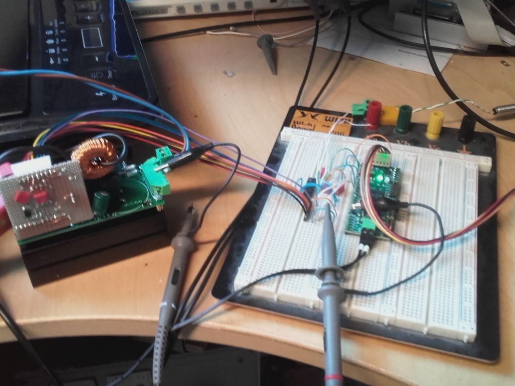
I've added a potentiometer to set the nominal current and a closed loop frequency control that adjusts the NCO according to the power demand.
'' InductionHeating.spin2 '' Test program for induction hotplate with MOSFET half bridge { current transformer ratio 1:167, 50A peak primary -> 0.3A secondary 2 ohm shunt resistor -> 0.6V peak input voltage, AC coupled ADC mode x3.16 gain, +/- 0.8V range, 12 bits resolution (signed) 2048 LSBs = 66.66A, 30.72 LSBs = 1.0A RMS value is calculated once per NCO cycle (20kHz to 60kHz) Voltage and current varies during a power cycle (100 or 120Hz half sine wave) of rectified mains voltage because we don't use a big electrolytic cap on the DC bus. This would only result in a poor power factor. The required cap and PFC inductor would cost more than a bit oversized MOSFET to handle the higher peak current. To get constant current readings we have to average it over a (multiple of) full power cycles. A PID cycle of 20Hz is used to fit both European and USA power grids. The so called PID control is acually a pure I control. Because the current measurement and LC time constant is ~1000 times faster than the 20Hz cycle there is virtually no delay and the integrator produces no overshot. The I-gain is adapted to the frequency so the gain is lower close to the resonant frequency to compensate the non-linear frequency to power relation. } CON _xtlfreq = 25_000_000 _clkfreq = 180_000_000 '_BAUD = 230400 ' serial debug port pidPeriod = _clkfreq / 20 ' common divisor of 100 and 120Hz ' Pins pinPwm = 8 ' PWM output pinEna = 10 ' power stage enable output pinAdc = 12 ' current transformer ADC input pinPoti = 14 ' potentiometer for power command modeAdc = P_ADC + P_ADC_3X modeSinc3 = %10_1000 ' SINC3 filtering 256 clocks modePoti = P_ADC modeSinc2 = %00_1101 ' SINC2 sampling 8192 clocks modeNco = P_NCO_FREQ + P_OE ncoBase = $4000_0001 ' base period = 1 clock, phase = 90° nco1kHz = 23861 ' 2^32 * 1k / 180M minFreq = nco1kHz * 20 maxFreq = nco1kHz * 60 OBJ com : "jm_serial.spin2" VAR long offset ' average of 256 samples = center line for AC coupling long rmsCurr ' actual instanous RMS current (per NCO cycle) long actCurr ' actual RMS current (averaged over multiple power cycles) long status ' 0=off, 1= enabled, -1= error long nomCurr ' nominal RMS current long potiLo long potiHi byte cog PUB main | x, i com.start (_BAUD) StartAdc repeat ' endless loop nomCurr:= GetPotiCalib * 30 / 133 ' 0..30A com.str (string ("avg=")) com.dec (offset) com.str (string (" curr=")) com.dec (actCurr) com.str (string (" stat=")) com.dec (status) com.str (string (" nom=")) com.dec (nomCurr) com.tx (10) waitx (_clkfreq / 10) PRI StartAdc cog:= cognew (@adcCode, @offset) + 1 ' address of VAR into PTRA pinstart (pinPoti, modePoti + P_ADC_GIO, modeSinc2, 8192) potiLo:= GetPotiRaw potiLo:= GetPotiRaw wrpin (pinPoti, modePoti + P_ADC_VIO) potiHi:= GetPotiRaw potiHi:= GetPotiRaw wrpin (pinPoti, modePoti + P_ADC_1X) PRI GetPotiRaw : p repeat until pinr (pinPoti) ' wait for sample ready return rdpin (pinPoti) PRI GetPotiCalib : p | x x:= GetPotiRaw return (x - potiLo #> 0) * 4096 / (potiHi - potiLo) <# 4095 DAT '' cog for PWM and ADC processing ORG adcCode ' pin and event initialisation fltl #pinAdc fltl #pinPwm wrpin ##modeAdc,#pinAdc wxpin #modeSinc3,#pinAdc drvl #pinAdc wrpin #modeNco,#pinPwm wxPin ##ncoBase,#pinPwm wypin ##maxFreq,#pinPwm drvl #pinPwm drvh #pinEna setse1 #1<<6 + pinAdc ' event #1 = ADC sample ready setse2 #1<<6 + pinPwm ' event #2 = NCO overflow call #getDummy call #getDummy call #getDummy getct pTime addct1 pTime,pCycle getSample waitse1 rdpin x,#pinAdc ' get ADC sample sub x,diff1 ' two stage differenciation add diff1,x sub x,diff2 add diff2,x shr x,#12 ' reduce to 12 bits resolution zerox x,#11 ' clear invalid high bits mov avg,filt shr avg,#8 sub filt,avg ' 255:1 low pass filter add filt,x sub x,avg ' signed result = raw sample - average abs x cmp x,maxCurr wc if_nc jmp #overCurr ' shutdown on overcurrent mul x,x ' square add rsum,x add rcnt,#1 jnse2 #noRms ' calculate RMS after each PWM falling edge qdiv rsum,rcnt ' average of squares akpin #pinPwm getqx x qsqrt x,#0 ' root of average -> RMS current 'mov stat,rcnt mov rcnt,#0 mov rsum,#0 getqx rms adcDone setq #3 wrlong avg,ptra jmp #getSample noRms cmp rcnt,#1 wz if_nz jmp #adcDone ' right after RMS calculation... add psum,rms ' execute once per NCO cycle add pcnt,#1 jnct1 #adcDone pidCtrl ' execute once per 20Hz cycle qdiv psum,pcnt addct1 pTime,pCycle mov pcnt,#0 mov psum,#0 rdlong nom,ptra[4] wz if_z jmp #powerOff sub nom,act ' deviation = nominal - actual mov x,freq sub x,subFreq ' variable gain, closer to resonant -> lower gain shr x,#6 muls x,nom ' non-linearity corection sar x,#2 sub freq,x fges freq,##minFreq fle freq,##maxFreq wypin freq,#pinPwm getqx act 'mov stat,x jmp #adcDone powerOff getqx act drvl #pinEna mov rms,#0 mov act,#0 mov stat,#0 waitOn setq #3 wrlong avg,ptra rdlong nom,ptra[4] wz if_z jmp #waitOn mov stat,#1 jmp #adcCode ' restart overCurr drvl #pinEna wrpin #0,#pinPwm mov act,x neg stat,#1 setq #3 wrlong avg,ptra jmp #overCurr getDummy waitse1 rdpin x,#pinAdc ' get ADC sample sub x,diff1 ' two stage differenciation add diff1,x sub x,diff2 _ret_ add diff2,x maxCurr long 1536 ' max. current = 50A x long 0 diff1 long 0 ' sinc3 diff values diff2 long 0 filt long 2048<<8 ' offset filter rsum long 0 ' sum of RMS input samples rcnt long 0 ' count of samples per NCO cycle psum long 0 ' sum of RMS output samples pcnt long 0 ' count of samples per PID cycle pTime long 0 pCycle long pidPeriod freq long maxFreq ' current NCO frequency (control output) subFreq long nco1kHz * 15 ' offset for non-linearity correction avg long 2048 rms long 0 act long 0 stat long 1 nom long 0The coil in the plate is made of stranded wire with the strands coated with insulation varnish ("HF litz"). So I think the skin effect is not a problem. The decreasing current at higher frequencies is simply caused by the induction getting dominant over the capacitance of the resonant circuit. Of course, there is a remarkable skin effect in the pot bottom but this is self-regulating. As resistance of the pot core (secondary winding of a transformer) gets higher the Q factor of the resonant circuit increases causing higher voltage swing.
The induction hot plate I opened up, the individual stands looked like 24awg (.25mm^2). That gives an upper frequency of 68KHz before skin depth becomes an issue.
A solid copper wire of the size used in the hot plate would probably be (6awg) closer to 1.1KHz.
I've added bigger caps and a fan for cooling. Now it works really well.
Nice work!
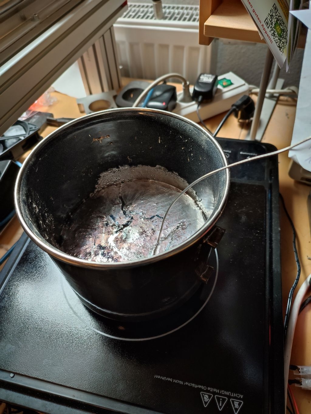
It not only cooks water but also melts a pot of soldering tin.
The electronics stay quite cool (heatsink ~35°C, DC bus cap ~60°C, resonant caps ~40°C) but the wires to the induction coil get pretty hot. While the ampere meter shows only 4A AC input current before the rectifier the current through the induction coil is around 25A which is a bit high for an AWG15 wire.
BTW, the thermocouple measurement displays 217°C when the tin starts to melt what is exactly the lower melting point of lead free tin (SAC307). Seems to be more accurate than in boiling water where it says 96°C.
Actually, this should be no surprise as the tin evaporates much, much less than water does so the tin vapors do not cool off the thermocouple probe housing as much as water vapors do. If you used the same probe pictured above for both measurements, that is. And in the above picture the probe housing is surrounded by mostly hot air (tin vapors are practically negligible) Speculation ? Perhaps, but plausible. So maybe the direct thermocouple measurement isn't as inaccurate as you previously determined ? That would be good news if proved right.
Well, could be... But to tell something real about accuracy multiple instances of the circuit should be build and measured under different environment conditions and with a calibrated reference thermometers. I don't have the time for that. I'll build an alternate setup with a MAX31855 and decide which one does the job better. If I only build a single machine with a single thermocouple the $6 for the MAX chip can be neglected. But I don't like the fact that the temperature vs. voltage chart is hardwired into the chip. If you change the type of thermocouple you have to buy a new chip. I'd prefer a flexible solution which implements the calculations for the compensation in software.
I don't think that vapors or air/gas flow in general does have a big influence on the results if at least 5mm of the the thermocouple tip is immersed in liquid. The thermal conductivity of the liquid is ~1000 times higher than that of the gas. Re-condensing vapor of course can carry a lot of thermal energy but it heats instead of cools. That's how vapor phase ovens work.
BTW, I'll need some more temperature sensors for safety to detect possible overheating of the driver heatsink, the coil and the pump motor. But there, cheap NTC resistors should do as used in 3D printer extruders. They can be measured directly with the P2 ADCs in X1 mode without any calibration. 10° more or less doesn't make much difference, there.
Good points.
Having calculations in software is way more flexible and cheaper in the long run. I'm very far from convincing you to make the test setup. That would be an overkill in this case. After all, you intend to melt solder tin and not boil water. Nor is it a scientific experiment but just a practical approach to a problem.