

Data corruption - and me being out of ideas
 __deets__
Posts: 216
__deets__
Posts: 216
I know this is a bit of a moonshot, as the project is probably a bit too complex for anybody to just step up and point out the mistake I'm making. But I'm out of ideas and maybe this helps.
I'm currently working on a data logger application using the P2. As ADC we use an ADS1256. The P2 is used in form of the P2-eval-board Rev C, and I have the HyperRAM extension. The data is streamed via serial line, and also supposed to be stored on SD-Card.
The architecture is roughly like this:
- cog 0 is the main program, and shovels data from the ADS into the HyperRAM for a hard-coded amount of seconds. It is triggered by a button-press on the button accessory, and another button makes the system write the data to a new file as well.
- cog 1 is the HyperRAM driver
- cog 2 is the ADS driver. It fills a relatively small ringbuffer with data.
- cog 3 is the serial streaming cog, and possibly writes the data to FAT. I use the wuerfel_21 FAT/sd card driver. It is trivially tweaked to remove audio code and an ill-fated attempt to tweak the SPI timing, until I learned that the throughput problem we see is the SD-card signalling to be busy.
You can find the main project file here: https://github.com/deets/unifhy-rocket-engine-test-stand/blob/master/modul2/P2/spin/hyper_ringbuffer_test.spin2
Now when I just fill the HyperRAM and then stream it out via serial line, things are hunkydory. See the attached image:
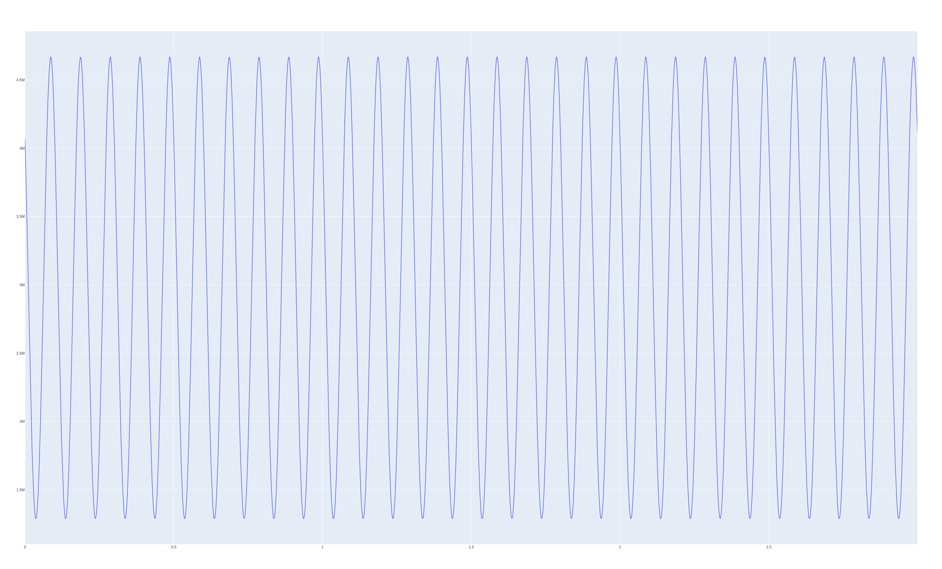
The data comes from my signal generator with a 10Hz, 4V swing sine wave. Looks legit.
Now when I start using the SD-card, things look massively different. Like this:

This is a run where I only set up the file writing, but do not actually write data. This leads to the beginning being distorted, but then the end to the right is actually well-formed when you would zoom in.
When I write continuously the results look like this: 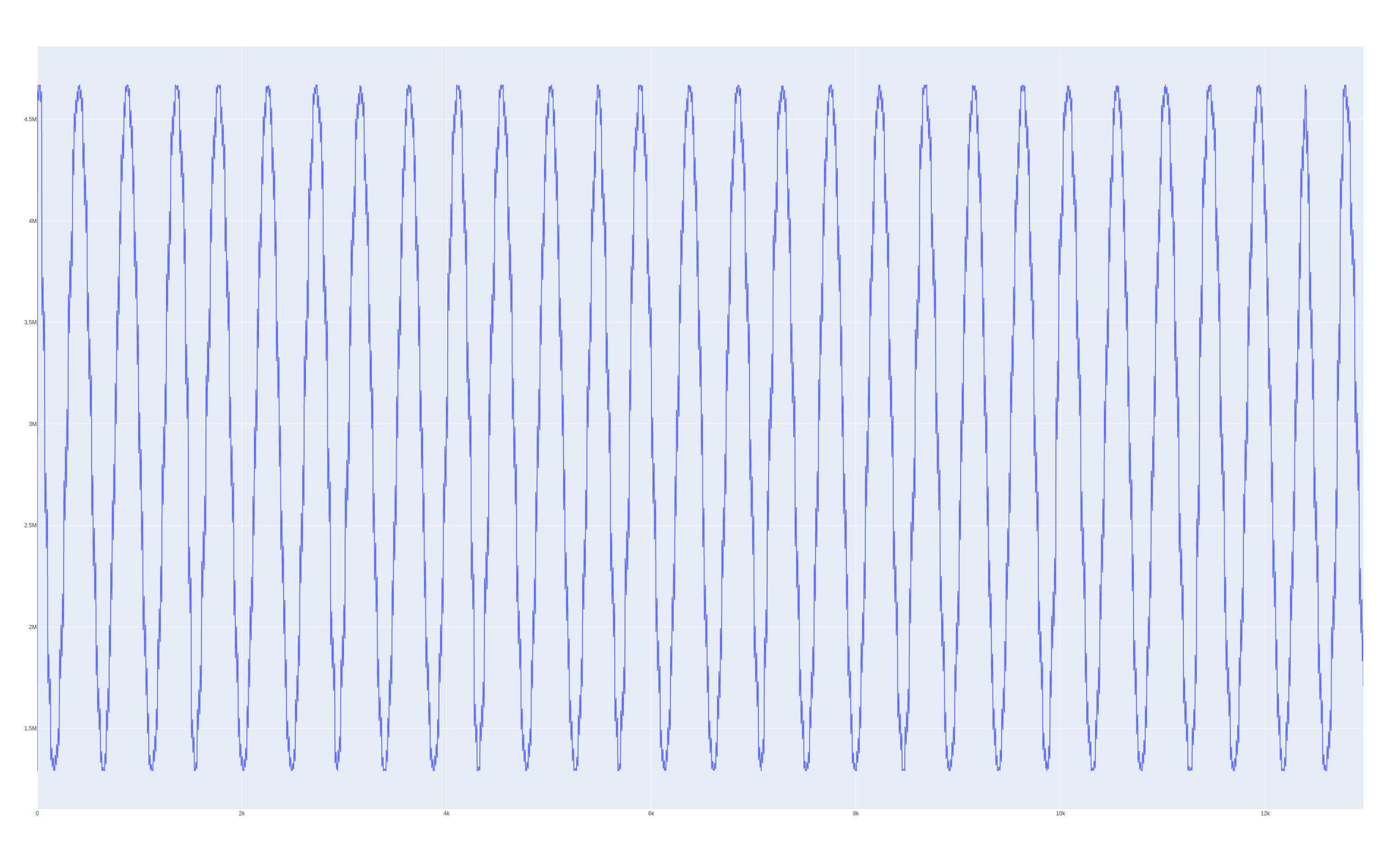
So it is differently distorted.
I have determined that the problem is not on the ADS reading side (analog distortion of some sort, or spi data with interference or some such) by determining the maximum difference between two consecutive values. This is in a consistent range determined by the applied signal.
I also determined the HyperRAM ringbuffer is not at fault, if I produce artificial data when filling it (simple sawtooth pattern using a counter + modulo), both serial and FAT data are as expected.
Only when using the real data I get these distortions. Now it could of course be that my little ringbuffer between cog 0 and cog 2 is somehow corrupted. No idea how, but fair enough. Thanks to the large memory of the P2 I can shift that around though, and that's what I did: I added a few kb of padding on both sides around it, but that didn't affect things.
I'm happy about any suggestions as to what I could try get to the bottom of this.
Comments
In that second picture it almost looks like it is displaying the value of the address, not the data at that address.
If it makes you feel better, I have never successfully implemented a ring buffer that straddles two cogs without a LOT of cussing. Of course, I’m also not much of a coder, so…")
First let me make sure I understood you correctly.
Cog 2 reads the data and writes to a ring bugger.
Cog 0 reads the ring buffer and sends the data to Cog 1. How do Cog 0 and 1 talk to each other?
Cog 1 writes to HyperRam.
Cog 3 reads from HyperRam and wries to the SD. Is that correct?
First question. If one guy is writing to a ring buffer, and the other guy is reading from it, you have to make sure that they go the same speed. How do you do that? With locks? Please link to the specific ilnes of code.
Second question, can you subtract your written data from the signal generated data to see what the distortion is? Maybe there is information in that.
Third question. You said you did not write the data, just opened the files. So all of those images are taken from data in the Hyper Ram. Is that correct?
Here is a stupid suggestion: Odd/Even cogs can talk to each other directly. They share high cog memory.
Maybe if you transmitted the data between the cogs that way it would work. Assuming the receiving cog is faster than the sending cog. Maybe you do that already between 0 and 1.
Hope that helps. Often when I explain things to someone else, it helps me to better understand and see the problem.
The next day:
Good Morning.
A ring buffer is a great idea.
I think it is such an important component for so many P2 projects.
Of course very hard to get it working correctly. The thing to do is to create it as a separate component with a full test suite.
Chris
Looked through your program @deets , didn't see anything obvious, but I didn't go through it with the fine tooth comb.
It might be a memory corruption bug affecting your ring buffer addressing perhaps. If you need to invoke the SD card code to trigger it, I'd start walking through that code and paring out parts of it until the problem goes away, and print pointers of interest along the way to pinpoint when the corruption is triggered. You could also try to shrink the buffer size down and have your ring buffer code dump out the address/data every step to see when things go awry. Hopefully you'll find it soon enough. Let us know if you find it.
Also you could reorder this code:
pri reader(use_sd) | entry[2], count, success, pos
  count := 0
  serial.start(RX0, TX0, %0000, BR_SERIAL)
  if use_sd
    start_fat()

  pollatn()
  repeat until pollatn() == -1
to become this instead, to see if that makes a difference, and you could also dump your data before the start_fat is called to make sure it is still okay at that point.
pri reader(use_sd) | entry[2], count, success, pos count := 0 serial.start(RX0, TX0, %0000, BR_SERIAL) pollatn() repeat until pollatn() == -1 if use_sd ' Note: you may have to add a way to ensure this is only called once if the loop repeats start_fat()@deets You could also check if the result of the HyperRAM access is somehow in error after you read it below. If it is a negative value returned by your call to mem.read that would likely indicate some type of mailbox address structure corruption in HUB RAM. If that occurred it would not be returning correct data.
pub fetch(address) : result if available() mem.read(address, RAM + read_pos * datagram_size, datagram_size) ' you could double check this result is zero return TRUE else return FALSE@rogloh thanks for your efforts.
I have verified through artificial data that the HyperRAM-part of the equation is not the problem. The data came always clean through.
I just this morning did a second experiment, where after reading the values from the ADC I replaced them with generated sawtooth data (modulo counter + counter as timestamp).
The non-SD-card-case looks as expected:
However when adding the SD-Card into the mix, this is the result:
So there does seem to be an issues transferring the data from cog 2 to cog 0. I'll investigate more (probably after my beginning work week, sigh).
@lozinski your observations about the system architecture are correct. The ringbuffer does not need synchronization through locks though, because I implement it with one write pointer and one read pointer who are modified only in their respective cogs. And the HubRAM should guarantee that reading or updating these pointers is atomic. As a consequence, I can just diff the two pointers (accounting for the case that write is smaller than read due to wrap over) and wait until data is available. Which happens in
adc.read_continuous(), which is frombuffered_ads*.spin2parallel to the main file. You misunderstood how the sd card is involved. The data is always relayed through a small buffer from cog2 to cog0, and cog0 stuffs it into the HyperRAM. The streaming cog streams this through serial, and depending on the users choice to SD-card. The case above was just setting up and closing the file, not actually writing the data. See https://github.com/deets/unifhy-rocket-engine-test-stand/blob/60724af1d3f9254faa72b734d84ad7a9bf190629/modul2/P2/spin/hyper_ringbuffer_test.spin2#L144 - it is commented out.I reckon that SD setup code is somehow trashing some important information in HUB RAM. You might try a test where you defer its init until after all the ADC data has been written into both buffers and once the reader COG gets notified and see if that makes a difference. Right now if SD is enabled, it will do its init early at the spawning of the reader code, which happens before the ADC data is started. That SD init might be somehow clobbering your pointers somewhere perhaps and this test would help isolate it. Be a good quick test to do.
Update: You could also dump out writepos, readpos and wpos etc via DEBUG statements perhaps to ensure that they increase as you expect when you feed/store and fetch data from your ring buffers etc, and also check that the configured output_buffer_address and output_buffer_size variables remain unchanged throughout. I think outputting these will help you debug things. Of course by shrinking down the buffer size and capture amount you won't need to generate massive amounts of data to wade through in the test.
Are you sure that your ringbuffer works as expected? I guess that your problems are cause by timing differences. If you only use synthesized data (modulo counter) and do not write to SD card then you never have significant delays. That means your ring buffer never contains more than one entry. If you write to SD the cog reading from the buffer is delayd from time to time causing the buffer to fill up. Did you protect the control structure of the ring buffer (pointers and counters) with hardware locks or software semaphores?
I'd ouput read and write pointers via DEBUG statements together with the data as Rogloh suggested.
You might also try increasing the stack size if the use of the SD card init code needs a bit more stack, although hopefully 2k longs is already enough.
@rogloh very interesting suggestion. Ultimately I want the streaming to occur in parallel du to it being critical data I want on some flash medium before a power outage in the 🚀 destroys it. But as investigative measure it’s a smart thing to try!
@ManAtWork Im reasonably sure my ringbuffer works. It works under the assumption that rdlong is atomic. I hope that’s true. It would also be something I expect to fail independent of the SD-card, because any races between Cog 0 and Cog 2 would happen regardless of Cog 3 using the SD-card or not.
And while I synthesized the data, it did not affect the timing, as I still drove the ADC, I just threw away the resulting data & instead synthesized it.
Bytes, shortwords, and longwords are each individually atomic.
Beyond that there is less assured solutions. One is to make use of the burst read/write ops ( SETQ+WRLONG, SETQ+RDLONG). This has caveats though. A biggie is can't be using the streamers FIFOs of the relevant cogs as that will intermittently stall the burst op. And said cogs must all perform the same length burst op on the shared hubRAM block.
I'm no spin wiz but the main repeat loop starting new cogs looks suspect. EDIT: In particular the "reader" cog is in turn starting another two cogs for serial and FAT. So each loop starts another three cogs right there.
@evanh i was a bit surprised it works stopping/starting myself. However I’ve done this often enough to know I’ve done it fresh after a reset as well. I will keep it in mind though!
Your burst read write comments I don’t understand. Can you elaborate?
You said you moved the ring buffer.
That was not the problem.
Try moving the write and read pointers.
Maybe they are getting corrupted.
I am also mindful of what the other person said:
"I never could get a ring buffer to work"
I like what @ManAtWork and @rogloh said about logging the data. You probably tried that already. Of course that may change the timing. In Python there is an assert statement.
You could do a consistency check on the ring buffer pointers and the amount of data copied. If it failed, stop the process, and report.
One other obvious question. Do you see a pattern in the data?
Are you plotting points, or lines between points? Maybe you are plotting the lines.
Maybe better to plot the points. If it were a horizontal line between two points, I would
say you are reading a point twice. A nearly vertical line, you skipped some data.
Your third plot has some jitter in the data. Plot it as points, and zoom in, it may provide a clue.
Maybe not.
Chris
I didn't see any explicit stopping for those three that I've highlighted.
It's based on the fact that, when a cog's FIFO is idle, a burst of consecutive addresses, once in motion, also has tight order that no other cog/FIFO can break into. The consecutive addresses are read/written on successive clocks. And, as long as every cog does the same bursting at the same hubRAM starting address, they create a natural atomic block transfer.
Bear in mind that hubexec uses the FIFO. So any program using this idea has to live inside all the cogs involved.
EDIT: Chip's Spin2 VM may not use the FIFO. Eric's compiled spin2 code certainly does.
Yes @evanh multiple COGs repeatedly being spawned is not ideal. I noticed too yesterday but I think it works here because the reader COG itself shuts down at the end of its repeat loop, and both the FAT32 and serial COGs each first call internal stop() methods when they are restarted. That's why @deets code doesn't run out of COGs.
The bit I don't like is during startup of the reader COG as it depends on the fact that its repeat loop needs to begin before the data is completed to catch the ATN signal properly from the COG that spawned it. If start_fat() takes too long to execute the data might be over by the time the repeat loop begins, and there's an unknown/random delay involved here. I guess that first pollatn will help catch this case and skip all the data if that occurs, but it is not fully clean IMO.
I think the main thread should just wait until it knows the reader COG is fully up and ready for its data before it begins, that's cleaner. It's probably not the real bug though.
pri reader(use_sd) | entry[2], count, success, pos count := 0 serial.start(RX0, TX0, %0000, BR_SERIAL) if use_sd start_fat() pollatn() ' <<< Ideally we would like the main COG to continue only after we reached here. Maybe add a COGATN back to the main COG here repeat until pollatn() == -1 repeat while rb.available() rb.fetch(@entry) count += 1 pos := prepare_line(entry[0], entry[1]) 'pos := prepare_line(count, count +// 1024) ' if use_sd ' write_to_fat(pos) serial.str(@line_buffer)@rogloh good catch, but this isn’t the real code. It’s a simplified version to track the issue. The real code properly mutually signals, and also doesn’t spawn cogs, but spins them up only once.
@evanh still a bit above my current understanding but I presume with hubexec you mean streaming code form HubRAM instead of using CogRAM? I don’t see this having an impact on Ring Buffer correctness though given there is only one reader and writer on the respective locations. Or would you see that as issue?
My spiel on atomic block access is a theoretical mental exercise of what could be done. I've not tried to fit it to your use case, nor do I know if it is what you need.
I still think that the straight diagonal line in the last image shows the address of the buffer, not the content.
Maybe you are barking at the wrong tree?
Mike
@msrobots I don’t understand your suggestion. What’s the wrong tree - data corruption?
The ringbuffer implementation is here:
read: https://github.com/deets/unifhy-rocket-engine-test-stand/blob/60724af1d3f9254faa72b734d84ad7a9bf190629/modul2/P2/spin/buffered_ads1256.spin2#L65
available: https://github.com/deets/unifhy-rocket-engine-test-stand/blob/60724af1d3f9254faa72b734d84ad7a9bf190629/modul2/P2/spin/buffered_ads1256.spin2#L82
write: https://github.com/deets/unifhy-rocket-engine-test-stand/blob/60724af1d3f9254faa72b734d84ad7a9bf190629/modul2/P2/spin/buffered_ads1256.spin2#L149
I think the point is the corruption seems very coherent, and far from random, and also unrelated to the data examples. That in itself may offer a clue.
When testing read-write paths, one test I've used is a rolling pattern that is carefully not the same on every page.
eg for testing a 64k buffer, a simple XOR of upper and lower bytes of address, used as data, has a value that is not the address, and also differs on every page.
Try an incrementing and then decrementing test pattern cases of that, and see if the faulty output changes in any way, in response to the pattern change.
"However when adding the SD-Card into the mix, this is the result:"
Your last image with sd shows a straight diagonal line.
That seems to me that you not save the data but the address or a index or I don't now.
But being a straight line points to outputting the index not the value and your buffer is completely OK.
Just guessing but might be a missing # (in PASM) or a missing @ (in SPIN) so a not dereferenced pointer somewhere?
Mike
so write_to_fat(pos) writes the pos not the line_buffer?
Mike
@msrobots , from what I gather deets corrupted data is actually coming out via the serial text dump, and the SD write itself is disabled during the test.
Also while that write_to_fat(pos) call is only passing in the length of the line to be written, internally it still uses the line_buffer array in that method as the source of the data which is populated previously with prepare_line(). So that should be fine also. Once the buffer pointers/data gets dumped to debug output while data is being stored and retrieved the corruption problem will probably be identified. Printf debugging still works wonders and Chip's DEBUG infrastructure allows multiple COGs to share the same serial output too.
Tiny bit of progress: the diagonal single line above was a red herring. It was just the second and subsequent runs that showed this shape, and the reason was a lingering datapoint in the ADS ringbuffer. I cleared that out. And then I discovered another problem: the display code aggravates and confuses the whole picture because it actually tries to do a clock-tracking of the propclock. It's basically a lowpass that filters clock timestamps. But if you feed that garbage, the results are.. interesting. So I removed that and replaced it with a simple consecutive counter value - and the picture literally looks very different:
These gaps are not 0 (that's just a scale thing) but in fact steps that contain the current index as timestamp value. And the lower byte of that index as analog value as it seems. This is a snippet out of my serial data:
The line I marked is line 1249, which happens to be $4E1 in hex. And it is the first vertical gap in the image.
So that's some mild progress, one bug down (stale buffer contents) and something that looks at least as if it is not total random.
Thanks for all the thought provoking suggestions. I'm on to especially @rogloh's debug statement for the ring states.
So I think I figured out a bit more on what's going on. Subsequent runs would not show the above pattern, but essentially periods of phase-shifted sinusoidal data. Which means that the reading (and then streaming) of data accesses old data. The data we see in the last post is consistent with me producing synthesized data, namely a count + count % 1024. Which would pan out to the exact pattern we see. So it appears as if the writing of fresh data into the HyperRAM ringbuffer (or buffer, as currently I'm not using it "ringingly") gets disturbed. And the reading just reads stale data in that case. I will take a look at @rogloh's driver to see if I can spot something that indicates.
My attempts at synthesizing data before writing were just to simple (good lesson for the future), because writing the same sawtooth waveform based on the running index obviously is not really useful.
I will also attempt to physically relocate the accessory boards. Currently the HypeRAM-expansion is seated directly besides the SD-card slot. If crosstalk of some sort is at play here (currently my only hypothesis, happy for more suggestions) it should be reduced or removed moving the expansion board.
Ok, I just did that. I flipped the accessory boards around. The HyperRAM now has base 32 instead of base 0 on the P2 eval board. Holy 🐄! The data is coming through clean. @rogloh any thoughts?
Which rev of the eval board do you have?
Trace length matching was added to one of the banks for revB and I think two on revC.
Can't recall now, but could go have a look later if you're interested which banks on your eval version would be best for high speed stuff. (or rogloh may also recall off the top of his head, as he's the master at the high speed thing!)
It's a RevC