

What am I doing wrong?
 AmbientPower
Posts: 16
AmbientPower
Posts: 16
in Propeller 1
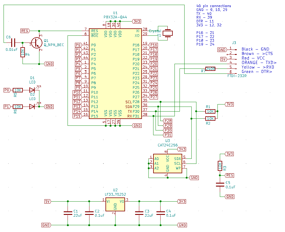
This is driving me nuts. I've put this on stripboard (with the 40 pin device) and cannot get SimpleIDE to detect it, I always get Error-1 on trying to load it. Tried on Mac and PC, reset signal is getting to the chip, voltages are fine, trying to load to RAM (I have not added crystal or memory at this stage).
I SHOULD be able to use an FTDI cable, shouldn't I? I'm planning a board using the chip and don't really want to add USB to the board.
Comments
Look at the schematic for prop plug. Resistors in tx and Rx , use decoupling cap. On power pins
Ftdi232
Use xtal, try spin tool also
Thanks, although I'm using the FTDI-232R-3V3 which has resistors built-in? decoupling on the PSU is next to the chip. I can see a load of activity after the reset, but I think that's from SimpleIDE.
OK, although I thought the crystal wasn't used for upload?
It's not.
I think that C5 may be causing your issue as the reset pulse from the transistor reset circuit is only a short pulse and may not discharge the cap quickly enough for the reset to be seen by the prop.
As a further comment, if you are protecting RX with R7, do the same in the TX line.
You'll need each and every of four 0.1 uF high frequency ceramic capacitors, almost tacked to P1 VDD pins.
There are four GND pins nearby, wich will easy your placement job.
By the way, welcome to Parallax Forums!
There's a known failure mode for the Prop1 when the bypass caps are omitted, in that the PLLs fail. The failure is permanent and can't be restored after the fact by adding the caps.
-Phil
I have a board that uses the Q44. First I solder all the decouple caps. , then the Q44 and xtal. After that I power it up and F7 with a external an prop plug using the spin tool, if that checks out I'll load the ram. Next comes the eprom and on board FT232. I've had blown chips but would still load. Spintool is my choice over IDE,
Ouch! That’s severe and fragile. Also not shown in the documentation.
Thanks to all so far.
Loads more decoupling, still nothing. 3.3V line is stable. Reset pulse 240uS. Traces show 1 - reset, 2/3 -serial lines, 4 - 3.3V supply (on AC). I've tried RCFAST, GENERIC board types, still nothing. Should the P1 be sending some data after reset, or does it wait for the host to send something first?
Check your reflow pin contact, if your using the Q44, I like to hit each pin with the narrow tip pencil iron, if I'm troubleshooting.
I add 4 ea. holes and traces to all of my boards to accommodate a prop plug for testing. It's nice to have a prop plug in your tool kit.
I’m using the 40pin DIP for now, and I’d like to use the FTDI cable that I use for most of my other boards. The only difference seems to be the reset circuit?
Yes, the host is supposed to be sending data first (basically just some "magic" bit sequence to prevent accidential programming). So the issue is likely something with your PC's serial port configuration.
Also, add a series resistor before or after C6, the strong TX drive from the Propeller can couple into the reset line and trigger spurious resets
I suggest investing in a prop plug and a spare P1 dip 40, but for now you can look over these two schematics and come up with a solution. Your P1 maybe bad, sometimes they are totally inoperative, other times they will function, but some pins maybe blown or the counters don't work.
I noticed the FT232 doesn't have DTR, only CTS to the cable.
It has RTS, I’m using that. I think Parallax may invert the RTS or DTR outputs on their FTDI chips, but I haven’t tried that yet. Makes sense when you look at the reset transistor, and RTS is normally active low, but needs to be driven high for reset to switch the transistor on and reset low.
I have a Propeller QuickStart on the way to me as a sanity check…
This is the reset (1), TX (2) and RX (3) pins on the P1 on the Quickstart board. All works fine, and I'm downloading code.
On my own board, the chip response at reset+110mS after the computer starts transmitting, but somehow, the computer doesn't seem to see the TX pulse at reset +300mS. So, seems like the P1 is working. I don't have an EEPROM connected, but I'm downloading into RAM. I've tried two FT232 devices, one on a board, another is the FT232R-3V3 cable. Same effect using Mac or PC. Any ideas?
You could connect a 2nd uart (eg your FT232R-3V3 cable) to both test cases, and start a terminal, to capture the TX burst coming back from the P1.
Then, you can compare the info.
When you zoom into that TX burst, do they look the same ?