

Getting Started With FlySky I-BUS
 JonnyMac
Posts: 9,775
JonnyMac
Posts: 9,775
FlySky products support Futaba S.BUS output, as well as their own I-BUS protocol. Here's the skinny on FlySky I-BUS:
- Baud rate is 115.2K
- True mode, 8N2
- 2-byte header ($20, then $40)
- 14 channels sent as 28 bytes (channel values are 1000 - 2000)
- 2-byte checksum
The checksum is $FFFF minus the sum of frame bytes 0..29. I converted one of my S.BUS demos to work with I-BUS -- the conversion took about 10 minutes and it worked right away.
I get the feeling that I-BUS is intended to feed flight-controller boards, as I cannot find I-BUS servos. The upshot of I-BUS is that there is a telemetry port on the receiver and we might be able to send data from a remote P2 to the transmitter. I am going to look into that.
This is just a quick test program. Over the weekend I will create a proper object that will be as easy to use as the S.BUS object.
Program output:
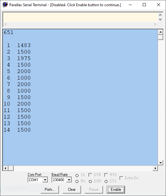
Note that I have a 10-channel radio so the last four channels in the frame default to 1500 (midpoint). There is no flags byte, but the failsafe outputs do kick in when the signal is lost.
14 MAY: I'm happy enough with my I-BUS object that I can release it.
05 APR 23: Dusted off the demo and added simply LED control from FS-i6X switches (per suggestion from Terry in thread).
Comments
cool
here a link to the telemetry https://github.com/betaflight/betaflight/wiki/Single-wire-FlySky-(IBus)-telemetry
Enjoy!
Mike
Thanks, Mike! -- that will helpful. I'm probably going to order a single sensor, anyway, and spy on the transactions.
I'm happy enough to with my I-BUS receiver object to release it (attached to first post in thread).
This is the output from that demo:
A very good news. I have a project at the university - the robot controller with remote control/sbus receiver. I have also several P2 Edge boards which I want to use in this project
You can find my S.BUS receiver code in the project files from this week's P2 session:
-- https://forums.parallax.com/discussion/173386/spin-2-for-beginners-futaba-s-bus
Now we have choices. For those with FlySky products, there is no need to switch to S.BUS as they're pre-configured for I-BUS. I suppose the advantage of S.BUS is the flags byte that alerts us to a dropped frame, or the receiver being in Failsafe mode. Anyway, both objects work nicely and have compatible method calls, so you move between them with no issues (other than checking for Failsafe mode).
Jon,")
If you haven’t already done so, i think this would make an extremely interesting Quick Byte which could then be submitted to hackaday.
This could be one of those killer apps for P2
I already committed to Ken that I'd write a Quick Byte about S.BUS since I just came off a presentation about it. I will follow up with I-BUS later, especially if I can sort out the telemetry feedback.
My wife bought me a FlySky FS-i6X for my birthday. I have been poking around with it this evening. I am a complete novice with the RC stuff, but have renewed my interest since my 11yo son has really taken to flight sims and flying RC planes.
Thanks for your work on this Jon! I am interested in sending telemetry back to the transmitter to be displayed via IBUS. Looks like it's going to be a fun challenge figuring out how to do that")
--Terry
Good stuff found here: https://github.com/adis1313/iBUSTelemetry-Arduino
How is that telemetry data treated on the transmitter side? Is it simple text data that is displayed without being interpreted? Or does a possibility exist to forward it to an external device? (serial interface)
It would be totally cool to implement some sort of primary flight display with artificial horizon, altimeter, airspeed, skid angle etc. Drones already have the required IMU built in but because pitch and roll are automatically controlled anyway the artificial horizon would not be of much use. But for fixed wing aircrafts bank and skid angle would be a good feedback to monitor the correct aileron and rudder input of the pilot. And the artificial horizon could be used for upset recovery or avoidance in the case visibility is poor, for example when looking into the sun.
More good stuff found here: https://github.com/cleanflight/cleanflight/blob/master/src/main/telemetry/ibus_shared.h
@ManAtWork I don't think you can display arbitrary data. In what little research I have done, it appears to be structured data.
With the 3rd part firmware that is available for their transmitters, who knows what is possible though!
I was on the set of a low-budget sci-fi series this weekend where the main character (played by actress Easton Alexeyev) is a wolf with lighted eyes and mechanical ears. The eyes are controlled with a pot but can't change in the scene because it requires a costumer. The ears can be moved with a cable mechanism, but that requires a puppeteer on the set and hidden in the shot, and the cables can restrict Easton's movements.
I told my producer friend about the SkyFly (as it matches their budge constraints). Since we're not shooting the next episode for a month or so, I'm going to see if I can get the iBus telemetry working on the P2, then back-port it to the P1 for the sci-fi project. Let's compare notes later. @"Ken Gracey" has a robot boat that he puts out on Lake Tahoe, it would be fun if he could control it with the SkyFly and get custom and standard telemetry values back.
I was able to get all 10 channels working as well. Even though the receiver is only 6 channels, I can get the other 4 from the ibus on the receiver. Without your code Jon, I would be SOL. Thank you!
I did have to pull the packaged jm_fullduplexserial.spin2 out of the directory, as it was the one with that used "field" as a var, which is now a reserved word. Deleting the file took care of the problem. Getting the data to actually display took a moment, because I didn't realize it was expecting you to press a key to start it up. I am not sure if that is needed.
I wish there was better documentation for the telemetry packet format. I can see the codeword and number of bytes sent for things such a temperature, altitude, speed, etc, but what I don't know is if a checksum is sent and if there is a magic codeword sent at the beginning of the packet. Trying to unroll Arduino code makes my head hurt. Guess I need to pick one up just to reverse engineer this protocol.
Yeah, changes that Chip made to the Spin2 interpreter stomped on jm_fullduplexserial.spin2 -- TWICE!
I'm thinking about plugging everything into a breadboard sand putting the servo and sensor ports on separate LA channels to get an idea of what's happening.
This link seems to pop up a lot in my searches for information.
-- https://github.com/betaflight/betaflight
Came across this image; I will compare with LA when I get a chance (though I only have two sensors [temp and voltage])
-- https://static.rcgroups.net/forums/attachments/1/1/0/6/2/5/a14850329-56-iBus-telemetry.png
Ah! that's some good insight there Jon! So it interrogates the sensors on a single wire type of connection. I see the 0x04 0x81 0x7A 0xFF being transmitted on the sensor bus. I assume the 0x81 means it is calling out to the sensor on address 1, based on the linked image in rcgroups.net
After looking at the image for awhile, this is what I suspect the Interrogatory and Response packets should look like.
First Octet
All Interrogatory packets start with $04
All Response packets start with $06, except for sensor exists detection echo.
Second Octet
Interrogatory & Response: $80+x Sensor Exists at address X
Interrogatory & Response: $90+x Sensor Type at address X
Interrogatory & Response: $A0+x Sensor Data at address X
Third Octet
Interrogatory & Response Sensor Exists: 2nd to last Octet
Interrogatory Sensor Type: 2nd to last Octet
Interrogatory Sensor Data: 2nd to last Octet
Response Sensor Type: Sensor Type code. See #defines below.
Response Sensor Data: MSByte of Sensor Data
Fourth Octet
Interrogatory & Response Sensor Exists: Last Octet
Interrogatory Sensor Type: Last Octet
Interrogatory Sensor Data: Last Octet
Response Sensor Type: Number of bytes returned for Sensor Data
Response Sensor Data: LSByte of Sensor Data
2nd to last Octet
Interrogatory & Response: Chucksum padding to make mod 256 $FF
Last Octet
Interrogatory & Response: Mod 256 Checksum: $FF
Progress. I can send the FS-i6x telemetry from the P2, but as soon as it sends interrogatories that I haven't programmed to expect, it goes away. That's OK, because this is just a proof of concept. Used jm_fullduplexserial in mode %0100. This allowed me to tie TX and RX pins together. I don't know if the data on this port is 8,n,1 or 8,n,2. That may be problematic down the road. Looks like it was in the above picture where they used 8,n,1, as some of the checksums are $FE and not $FF
**More Updates
OK, found that the last octet is different for Response Sensor Data. It ends in $FE. A 1ms wait is needed after the Interrogatory. Also, LSByte goes first.
So, this is the packet structure as I understand it:
First Octet
All Interrogatory packets start with $04
All Response packets start with $06, except for sensor exists detection echo.
Second Octet
Interrogatory & Response: $80+x Sensor Exists at address X
Interrogatory & Response: $90+x Sensor Type at address X
Interrogatory & Response: $A0+x Sensor Data at address X
Third Octet
Interrogatory & Response Sensor Exists: 2nd to last Octet
Interrogatory Sensor Type: 2nd to last Octet
Interrogatory Sensor Data: 2nd to last Octet
Response Sensor Type: Sensor Type code. See #defines below.
Response Sensor Data: LSByte of Sensor Data
Fourth Octet
Interrogatory & Response Sensor Exists: Last Octet
Interrogatory Sensor Type: Last Octet
Interrogatory Sensor Data: Last Octet
Response Sensor Type: Number of bytes returned for Sensor Data
Response Sensor Data: MSByte of Sensor Data
2nd to last Octet
Interrogatory & Response: Chucksum padding to make mod 256 $FF
Last Octet
All Interrogatory & Response except Response Sensor Data: Mod 256 Checksum: $FF
Response Sensor Data: Mod 256 Checksum: $FF - 1 ($FE)
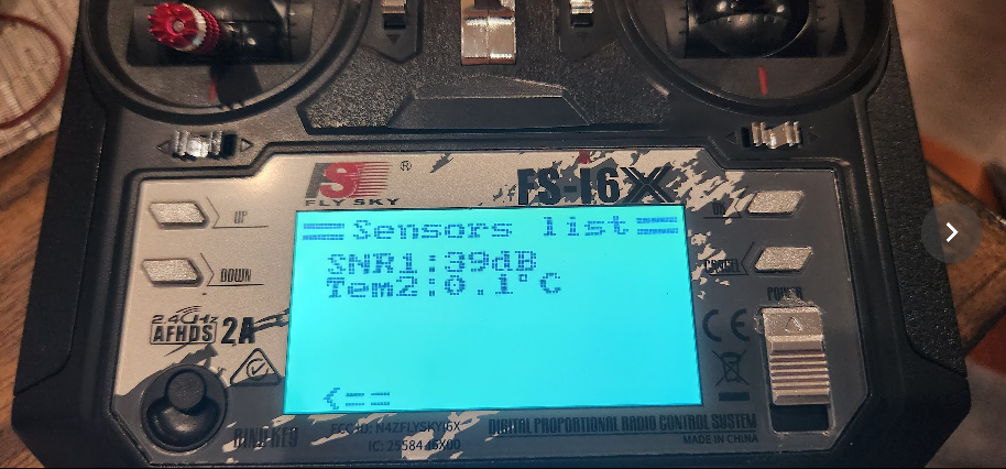
{Proof of Concept FlySky Telemetry} CON CLK_FREQ = 200_000_000 ' system freq as a constant RX1 = 2 { I } ' programming / debug TX1 = 3 { O } _clkfreq = CLK_FREQ ' set system clock OBJ telem : "jm_fullduplexserial" ' * serial IO for terminal PUB main() telem.start(RX1, TX1, %0100, 115_200) repeat until telem.rx() == $04 debug(uhex($04)) debug(uhex(telem.rx())) debug(uhex(telem.rx())) debug(uhex(telem.rx())) waitms(1) telem.tx($04) telem.tx($81) telem.tx($7A) telem.tx($FF) repeat until telem.rx() == $04 debug(uhex($04)) debug(uhex(telem.rx())) debug(uhex(telem.rx())) debug(uhex(telem.rx())) repeat until telem.rx() == $04 debug(uhex($04)) debug(uhex(telem.rx())) debug(uhex(telem.rx())) debug(uhex(telem.rx())) waitms(1) telem.tx($06) telem.tx($91) telem.tx($01) telem.tx($02) telem.tx($65) telem.tx($FF) repeat 6 debug(uhex(telem.rx())) repeat repeat until telem.rx() == $04 repeat until telem.rx() == $A1 repeat until telem.rx() == $5A repeat until telem.rx() == $FF waitms(1) telem.tx($06) telem.tx($A1) telem.tx($9A) telem.tx($01) telem.tx($BD) telem.tx($FE) repeat 6 debug(uhex(telem.rx()))A little further this evening. Made a packet parser and created a crude structure in memory for sensors. I can only get the "Tem2" sensor to work. Any additional sensors show up as "3" with a value of "0". I am missing something.
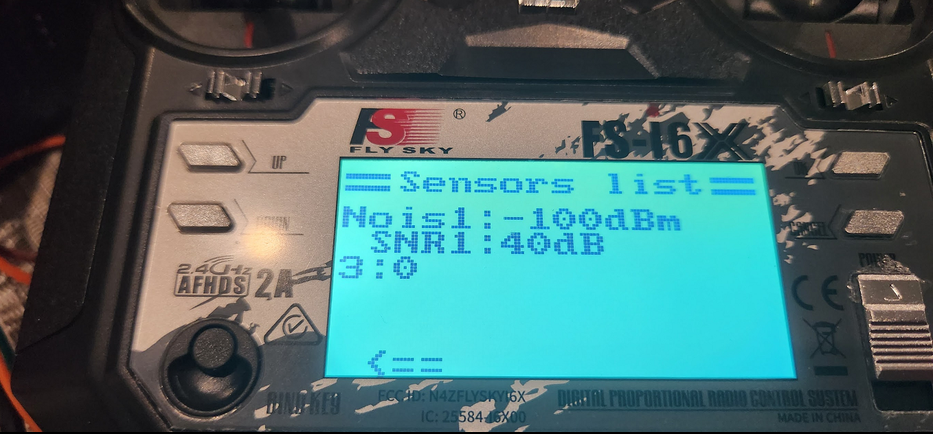
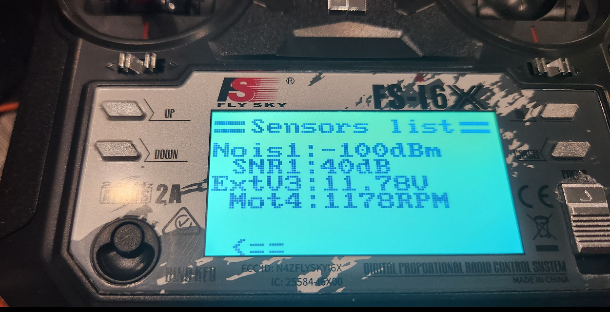
{Proof of Concept FlySky Telemetry} CON CLK_FREQ = 200_000_000 ' system freq as a constant RX1 = 2 { I } ' programming / debug TX1 = 3 { O } _clkfreq = CLK_FREQ Temp = $01 IBUS_MEAS_TYPE_TEM = $01 ' Temperature IBUS_MEAS_TYPE_EXTV = $03 ' External voltage IBUS_MEAS_TYPE_CELL = $04 ' Avg cell voltage IBUS_MEAS_TYPE_BAT_CURR = $05 ' Battery current IBUS_MEAS_TYPE_FUEL = $06 ' Remaining battery percentage IBUS_MEAS_TYPE_RPM = $07 ' Throttle value / battery capacity IBUS_MEAS_TYPE_CMP_HEAD = $08 ' Heading IBUS_MEAS_TYPE_CLIMB_RATE = $09 ' Climb rate IBUS_MEAS_TYPE_COG = $0a ' Course over ground IBUS_MEAS_TYPE_GPS_STATUS = $0b ' GPS status (2 values) IBUS_MEAS_TYPE_ACC_X = $0c ' Acc X IBUS_MEAS_TYPE_ACC_Y = $0d ' Acc Y IBUS_MEAS_TYPE_ACC_Z = $0e ' Acc Z IBUS_MEAS_TYPE_ROLL = $0f ' Roll IBUS_MEAS_TYPE_PITCH = $10 ' Pitch IBUS_MEAS_TYPE_YAW = $11 ' Yaw IBUS_MEAS_TYPE_VERTICAL_SPEED = $12 ' Vertical speed IBUS_MEAS_TYPE_GROUND_SPEED = $13 ' Speed m/s IBUS_MEAS_TYPE_GPS_DIST = $14 ' Distance from home IBUS_MEAS_TYPE_ARMED = $15 ' Armed / unarmed IBUS_MEAS_TYPE_FLIGHT_MODE = $16 ' Flight mode IBUS_MEAS_TYPE_PRES = $41 ' Pressure IBUS_MEAS_TYPE_SPE = $7e ' Speed km/h OBJ telem : "jm_fullduplexserial" ' * serial IO for terminal var byte packet[256] ' byte txpacket[256] byte sensor[60] { Sensor Memory Map Address,Type,Value1,Value2 } PUB main() telem.start(RX1, TX1, %0100, 115_200) sensor[0] := 1 ' Address sensor[1] := IBUS_MEAS_TYPE_TEM ' Type sensor[2] := $9A ' Telemetry LSByte sensor[3] := $01 ' Telemetry MSByte sensor[4] := 2 ' Address sensor[5] := IBUS_MEAS_TYPE_BAT_CURR ' Type sensor[6] := $5 ' Telemetry LSByte sensor[7] := $0 ' Telemetry MSByte repeat startpacket() PUB startpacket() packet[0] := 0 repeat until packet[0] == $04 || packet[0] == $06 packet[0] := telem.rx() packet[1] := telem.rx() packet[2] := telem.rx() packet[3] := telem.rx() if packet[1] >= $A0 && packet[1] <= $B0 sensortelemetry() if packet[1] >= $80 && packet[1] <= $90 sensorexists() if packet[1] >= $90 && packet[1] <= $A0 sensortype() return PUB sensorexists() | i repeat i from 0 to 14 if sensor[i*4] == packet[1]-$80 ' Do we have a sensor at requested address ? waitms(1) ' Repeat it back if we do telem.tx(packet[0]) telem.tx(packet[1]) telem.tx(packet[2]) telem.tx(packet[3]) repeat 4 ' Update the receive buffer to remove our echo telem.rx() debug("Sensor found at address ", udec_(packet[1]-$80)) return else debug("Sensor not found at address ", uhex_(packet[1])) return PUB sensortype() | i repeat i from 0 to 14 if sensor[i*4] == packet[1]-$90 ' Do we have a sensor at requested address ? waitms(1) packet[0] := $06 ' Construct the sensor type packet and send it packet[2] := sensor[i*4+1] ' Set Sensor Type packet[3] := $02 ' Set number of bytes in telemetry. All sensors are two bytes? packet[4] := checksum(4) packet[5] := $FF repeat i from 0 to 5 ' debug("Sensor Type", uhex_(packet[i])) telem.tx(packet[i]) ' abort repeat 6 telem.rx() ' Update the receive buffer to remove our echo debug("Sensor found of type ", udec_(packet[2])) return PUB sensortelemetry() | i repeat i from 0 to 14 if sensor[i*4] == packet[1]-$A0 ' Do we have a sensor at requested address ? waitms(1) packet[0] := $06 ' Construct the sensor type packet and send it packet[2] := sensor[i*4+2] ' Set Sensor LSByte packet[3] := sensor[i*4+3] ' Set Sensor MSByte packet[4] := checksum(4) packet[5] := $FE repeat i from 0 to 5 ' debug("Sensor Data", uhex_(packet[i])) telem.tx(packet[i]) repeat 6 telem.rx() ' Update the receive buffer to remove our echo debug("Sensor Data sent for Address ", udec_(packet[1]-$A0)) return PUB checksum(bytecount) : r | i r := 0 repeat i from 0 to bytecount-1 r := r + packet[i] r := r & $FF r := $FF - r return rScratch that. I have a few sensors working now.
{Proof of Concept FlySky Telemetry} CON CLK_FREQ = 200_000_000 ' system freq as a constant RX1 = 2 { I } ' programming / debug TX1 = 3 { O } _clkfreq = CLK_FREQ Temp = $01 IBUS_MEAS_TYPE_TEM = $01 ' Temperature IBUS_TYPE_MotorRPM = $02 ' Motor RPM IBUS_MEAS_TYPE_EXTV = $03 ' External voltage IBUS_MEAS_TYPE_CELL = $04 ' Avg cell voltage IBUS_MEAS_TYPE_BAT_CURR = $05 ' Battery current IBUS_MEAS_TYPE_FUEL = $06 ' Remaining battery percentage IBUS_MEAS_TYPE_RPM = $07 ' Throttle value / battery capacity IBUS_MEAS_TYPE_CMP_HEAD = $08 ' Heading IBUS_MEAS_TYPE_CLIMB_RATE = $09 ' Climb rate IBUS_MEAS_TYPE_COG = $0a ' Course over ground IBUS_MEAS_TYPE_GPS_STATUS = $0b ' GPS status (2 values) IBUS_MEAS_TYPE_ACC_X = $0c ' Acc X IBUS_MEAS_TYPE_ACC_Y = $0d ' Acc Y IBUS_MEAS_TYPE_ACC_Z = $0e ' Acc Z IBUS_MEAS_TYPE_ROLL = $0f ' Roll IBUS_MEAS_TYPE_PITCH = $10 ' Pitch IBUS_MEAS_TYPE_YAW = $11 ' Yaw IBUS_MEAS_TYPE_VERTICAL_SPEED = $12 ' Vertical speed IBUS_MEAS_TYPE_GROUND_SPEED = $13 ' Speed m/s IBUS_MEAS_TYPE_GPS_DIST = $14 ' Distance from home IBUS_MEAS_TYPE_ARMED = $15 ' Armed / unarmed IBUS_MEAS_TYPE_FLIGHT_MODE = $16 ' Flight mode IBUS_MEAS_TYPE_PRES = $41 ' Pressure IBUS_MEAS_TYPE_SPE = $7e ' Speed km/h OBJ telem : "jm_fullduplexserial" ' * serial IO for terminal var byte packet[256] ' byte txpacket[256] byte sensor[60] { Sensor Memory Map Address,Type,Value1,Value2 } PUB main() | i telem.start(RX1, TX1, %0100, 115_200) sensor[0] := 1 ' Address sensor[1] := IBUS_MEAS_TYPE_TEM ' Type sensor[2] := $9A ' Telemetry LSByte sensor[3] := $02 ' Telemetry MSByte sensor[4] := 2 ' Address sensor[5] := IBUS_MEAS_TYPE_EXTV ' Type sensor[6] := $9A ' Telemetry LSByte sensor[7] := $04 ' Telemetry MSByte sensor[8] := 3 ' Address sensor[9] := IBUS_TYPE_MotorRPM ' Type sensor[10] := $9A ' Telemetry LSByte sensor[11] := $04 ' Telemetry MSByte repeat startpacket() PUB startpacket() packet[0] := 0 repeat until packet[0] == $04 || packet[0] == $06 if packet[0] <> $00 debug("**** Unsyncronized Packet ****") packet[0] := telem.rx() packet[1] := telem.rx() packet[2] := telem.rx() packet[3] := telem.rx() if packet[1] >= $A0 && packet[1] <= $B0 sensortelemetry() return if packet[1] >= $80 && packet[1] <= $90 sensorexists() return if packet[1] >= $90 && packet[1] <= $A0 sensortype() return debug("**** Unknown Packet ****") return PUB sensorexists() | i repeat i from 0 to 14 if sensor[i*4] == packet[1]-$80 ' Do we have a sensor at requested address ? waitms(1) ' Repeat it back if we do telem.tx(packet[0]) telem.tx(packet[1]) telem.tx(packet[2]) telem.tx(packet[3]) repeat 4 ' Update the receive buffer to remove our echo telem.rx() debug("Sensor found at address ", udec_(packet[1]-$80)) return debug("Sensor not found at address ", uhex_(packet[1])) return PUB sensortype() | i repeat i from 0 to 14 if sensor[i*4] == packet[1]-$90 ' Do we have a sensor at requested address ? waitms(1) packet[0] := $06 ' Construct the sensor type packet and send it packet[2] := sensor[i*4+1] ' Set Sensor Type packet[3] := $02 ' Set number of bytes in telemetry. All sensors are two bytes? packet[4] := checksum(4) packet[5] := $FF repeat i from 0 to 5 ' debug("Sensor Type", uhex_(packet[i])) telem.tx(packet[i]) ' abort repeat 6 telem.rx() ' Update the receive buffer to remove our echo debug("Sensor found of type ", udec_(packet[2])) return PUB sensortelemetry() | i repeat i from 0 to 14 if sensor[i*4] == packet[1]-$A0 ' Do we have a sensor at requested address ? waitms(1) packet[0] := $06 ' Construct the sensor type packet and send it packet[2] := sensor[i*4+2] ' Set Sensor LSByte packet[3] := sensor[i*4+3] ' Set Sensor MSByte packet[4] := checksum(4) packet[5] := $FE repeat i from 0 to 5 ' debug("Sensor Data", uhex_(packet[i])) telem.tx(packet[i]) repeat 6 telem.rx() ' Update the receive buffer to remove our echo debug("Sensor Data sent for Address ", udec_(packet[1]-$A0)) return PUB checksum(bytecount) : r | i r := 0 repeat i from 0 to bytecount-1 r := r + packet[i] r := r & $FF r := $FF - r return rNeat stuff. Are you connecting the TX and RX pins together? This makes sense of using open-drain TX mode and dealing with one wire.
I'm going to liberate some of you ideas and see if I can create an object with a PASM2 cog that lets one specify the number of sensors in use, their type, and the ability to load a value from the parent. The background cog would simply listen for and process the requests (I may be trying to over-simplify). I started scribbling some inline PASM while having coffee.
con RX_MODE = P_ASYNC_RX TX_MODE = P_ASYNC_TX | P_OE | P_HIGH_FLOAT pub get_query(sio) : packet org wrpin #0, sio ' tristate mode wquiet mov pr0, #140 ' wait for idle ~1.5 byte periods .wq1 waitx #US_001 testp sio wc ' check state of rx pin if_nc jmp #wquiet ' if activity, restart wait djnz pr0, #.wq1 dirl sio ' reset smart pin wrpin ##RX_MODE, sio ' set rx uart dirh sio ' activate pkt_0 call #rx_byte cmp pr0, #$04 wcz ' verify 1st byte is $04 if_ne jmp #pkt_0 or packet, pr0 pkt_1 call #rx_byte shl pr0, #8 or packet, pr0 pkt_2 call #rx_byte shl pr0, #16 or packet, pr0 pkt_3 call #rx_byte shl pr0, #24 or packet, pr0 jmp #done rx_byte testp sio wc ' anything waiting? if_nc jmp #rx_byte rdpin pr0, sio ' read new byte _ret_ shr pr0, #24 ' align lsb done end pub ack_sensor(sio, packet) org dirl sio ' reset smart pin wrpin ##TX_MODE, sio ' set tx uart dirh sio ' activate mov pr0, #4 get_byte call #tx_byte shr packet, #8 djnz pr0, #get_byte jmp #done tx_byte rdpin pr7, sio wc ' check busy flag if_c jmp #tx_byte ' wait if busy wypin packet, sio ' load into sp uart ret done endThanks Jon. Yes, I am connecting both pins together. Something to keep in mind, this plugs into the sensor port, not the servo port which your monitor code above plugs into. So a total of three pins would be needed, unless we can get a 1 wire type serial object going. Not sure if that can be easily done.
I will try and build a better document for describing the behavior that I see from the receiver. Something of note, any response from the P2 must be less than 8ms, otherwise the receiver spits out another interrogatory packet. Also, I found that I needed to add a delay in responding, because when I turned off debugging, the receiver didn't understand what the P2 was sending. I set a 1ms wait for turnaround.
Many of the sensors listed above do not display properly in the receiver. I suspect that many of these sensors do display properly with the aftermarket firmware loaded on the transmitter. I will try and flash the firmware this evening to see if that is true.
BTW, I can't tell you how tickled I was to use your object to turn the lights on and off on the P2 Edge using the switches on the transmitter.
        if i == 5
          if ibus.read(i) == 2000
            PINL(LED1)
          else
            PINH(LED1)
        if i == 6
          if ibus.read(i) == 2000
            PINL(LED2)
          else
            PINH(LED2)
I think I am going to have a P2 Edge take flight to control some WS2811 LEDs for my plane. I can even strobe them once as second to full white to make my Super Cub look like the real thing!
I connected my LA to the servo and sensor ports (silly me, didn't do a screen cap); the transactions on the sensor line take place between the servo packets. This suggests that a single cog could handle servo and sensor data with two smart pins: one to RX the servo data, the other that is bi-directional for the sensor port.
It is. I do it with in my Dynamixel object. Assuming the smart pin has been setup with baud and bit count data, all you have to do is turn off the dir bit to reset it, use wrpin to set the mode (TX or RX), and then drive the pin to activate it. Easy-peasy
That makes me grin! -- so much so that I added controlling P56 and P57 LEDs from the demo using SwC and SwD on the FS-i6X transmitter.
My friend, Rick, has been using RC components to control props in the movie business for years. A long time ago I wrote a P1 object that would measure the servo pulses out of a standard RC receiver; he would convert those values into prop control commands. This image is of snowboarders covered with about 2K WS2812s that are controlled from RC transmitters (one per snowboarder). The snowboarders wore very heavy backpack with the batteries, RC receiver, and a P1 board Rick made.
This was for a Sony TV commercial.
It appears there are 2 and 4 byte sensors. https://github.com/qba667/FlySkyI6/wiki/Telemetry
I think I want to try this firmware on my i6. It has everything I want regarding GPS data being displayed.
I'm going to take a crack at a telemetry cog in the morning. I was hoping I could get an input pin to echo to an output pin (w/o software) which would have been helpful watching things on a logic analyzer, but I'll manage with a breadboard. Should be fun.
I spun up a cog with my code from your object. They both worked together, LOL. But I think we are using 4 cogs at that point.
obj
' main                                                          ' * master Spin cog
  ibus : "jm_ibus_rx"                                           ' * ibus receiver
  term : "jm_fullduplexserial"                                  ' * serial IO for terminal
  ansi : "jm_ansi"                                              '   ANSI terminal control sequences
  telemetry : "telemtest"
' * uses cog when loaded

{etc}

pub main() | t1, t2, i

  setup()
  COGSPIN(NEWCOG,telemetry.main(), @telemetrystack)
  wait_for_terminal(true)
  waitms(100)
{etc}
I flashed my transmitter with the most recent factory firmware and wasn't too happy with the sensor displays. The FlyPlus firmware looks like it has everything I want n regards to telemetry. I will try it this evening and report back how well it works.
https://github.com/qba667/FlySkyI6/releases/tag/1.7.6
FlyPlus is a no-go on the FS-i6X. It will work on the original FS-i6, but not the FS-i6X. Different MCU. The other alternative is OpenTX, but I don't like the UI. https://www.rcgroups.com/forums/showthread.php?3916435-FlySky-I6X-port-of-OpenTX
I will just keep piddling with the latest stock firmware. OpenTX looks like it has oddball problems. (Latency, things not working after updates, etc)
I just received my FS-CAT01 altitude sensor. After popping it on the analyzer, I have determined that the 1st octet actually contains the number of bytes that will be in the packet.
I will post more information about that sensor when I determine how that data is encoded. My most recent working code is below, with commented warts and all.
First Octet
Number of bytes within the packet.
Second Octet
Interrogatory & Response: $80+x Sensor Exists at address X
Interrogatory & Response: $90+x Sensor Type at address X
Interrogatory & Response: $A0+x Sensor Data at address X
Third Octet
Interrogatory & Response Sensor Exists: 2nd to last Octet
Interrogatory Sensor Type: 2nd to last Octet
Interrogatory Sensor Data: 2nd to last Octet
Response Sensor Type: Sensor Type code. See #defines below.
Response Sensor Data: LSByte of Sensor Data
Fourth Octet
Interrogatory & Response Sensor Exists: Last Octet
Interrogatory Sensor Type: Last Octet
Interrogatory Sensor Data: Last Octet
Response Sensor Type: Number of bytes returned for Sensor Data
Response Sensor Data: MSByte of Sensor Data
2nd to last Octet
Interrogatory & Response: Chucksum padding to make mod 256 $FF
Last Octet
All Interrogatory & Response except Response Sensor Data: Mod 256 Checksum: $FF
Response Sensor Data: Mod 256 Checksum: $FF - 1 ($FE)
{Proof of Concept FlySky Telemetry} CON CLK_FREQ = 200_000_000 ' system freq as a constant RX1 = 2 { I } ' programming / debug TX1 = 3 { O } _clkfreq = CLK_FREQ Temp = $01 IBUS_MEAS_TYPE_TEM = $01 ' Temperature IBUS_TYPE_MotorRPM = $02 ' Motor RPM IBUS_MEAS_TYPE_EXTV = $03 ' External voltage IBUS_MEAS_TYPE_CELL = $04 ' Avg cell voltage IBUS_MEAS_TYPE_BAT_CURR = $05 ' Battery current IBUS_MEAS_TYPE_FUEL = $06 ' Remaining battery percentage IBUS_MEAS_TYPE_RPM = $07 ' Throttle value / battery capacity IBUS_MEAS_TYPE_CMP_HEAD = $08 ' Heading IBUS_MEAS_TYPE_CLIMB_RATE = $09 ' Climb rate IBUS_MEAS_TYPE_COG = $0a ' Course over ground IBUS_MEAS_TYPE_GPS_STATUS = $0b ' GPS status (2 values) IBUS_MEAS_TYPE_ACC_X = $0c ' Acc X IBUS_MEAS_TYPE_ACC_Y = $0d ' Acc Y IBUS_MEAS_TYPE_ACC_Z = $0e ' Acc Z IBUS_MEAS_TYPE_ROLL = $0f ' Roll IBUS_MEAS_TYPE_PITCH = $10 ' Pitch IBUS_MEAS_TYPE_YAW = $11 ' Yaw IBUS_MEAS_TYPE_VERTICAL_SPEED = $12 ' Vertical speed IBUS_MEAS_TYPE_GROUND_SPEED = $13 ' Speed m/s IBUS_MEAS_TYPE_GPS_DIST = $14 ' Distance from home IBUS_MEAS_TYPE_ARMED = $15 ' Armed / unarmed IBUS_MEAS_TYPE_FLIGHT_MODE = $16 ' Flight mode IBUS_MEAS_TYPE_PRES = $41 ' Pressure IBUS_MEAS_TYPE_SPE = $7e ' Speed km/h IBUS_MEAS_TYPE_ALT_FLYSKY = $f9 OBJ telem : "jm_fullduplexserial" ' * serial IO for terminal var byte packet[256] ' byte txpacket[256] byte sensor[60] { Sensor Memory Map Address,Type,Value1,Value2 } PUB main() | i telem.start(RX1, TX1, %0100, 115_200) sensor[0] := 1 ' Address sensor[1] := IBUS_MEAS_TYPE_PRES ' Type sensor[2] := $04 'number of bytes sensor[3] := $76'%01010111'%01010111 '%01010111' 176'$b1 ' Telemetry LSByte sensor[4] := $85'%11111111 ' $0 '%11111111 '166'$a5 ' Telemetry MSByte sensor[5] := $41 sensor[6] := $14 { sensor[0] := 3 ' Address sensor[1] := IBUS_MEAS_TYPE_TEM ' Type sensor[2] := $02 'number of bytes sensor[3] := $9A ' Telemetry LSByte sensor[4] := $01 ' Telemetry MSByte sensor[5] := $00 sensor[6] := $00 sensor[7] := 2 ' Address sensor[8] := IBUS_MEAS_TYPE_EXTV ' Type sensor[9] := $02 'number of bytes sensor[10] := $9A ' Telemetry LSByte sensor[11] := $04 ' Telemetry MSByte sensor[12] := $00 sensor[13] := $00 sensor[14] := 1 ' Address sensor[15] := IBUS_MEAS_TYPE_PRES ' Type sensor[16] := $06 'number of bytes sensor[17] := $76'%01010111'%01010111 '%01010111' 176'$b1 ' Telemetry LSByte sensor[18] := $85'%11111111 ' $0 '%11111111 '166'$a5 ' Telemetry MSByte sensor[19] := $41 sensor[20] := $14 }{ sensor[21] := 4 ' Address sensor[22] := IBUS_MEAS_TYPE_ALT_FLYSKY ' Type (Sats? sensor[23] := $02 'number of bytes sensor[24] := $12 ' Telemetry LSByte sensor[25] := $01 ' Telemetry MSByte sensor[26] := $00 sensor[27] := $00 } repeat startpacket() PUB startpacket() packet[0] := 0 repeat until packet[0] == $04 || packet[0] == $06 if packet[0] <> $00 debug("**** Unsyncronized Packet ****") packet[0] := telem.rx() packet[1] := telem.rx() packet[2] := telem.rx() packet[3] := telem.rx() if packet[1] >= $A0 && packet[1] <= $B0 sensortelemetry() return if packet[1] >= $80 && packet[1] <= $90 sensorexists() return if packet[1] >= $90 && packet[1] <= $A0 sensortype() return debug("**** Unknown Packet ****") return PUB sensorexists() | i repeat i from 0 to 14 if sensor[i*7] == packet[1]-$80 ' Do we have a sensor at requested address ? waitms(1) ' Repeat it back if we do telem.tx(packet[0]) telem.tx(packet[1]) telem.tx(packet[2]) telem.tx(packet[3]) repeat 4 ' Update the receive buffer to remove our echo telem.rx() debug("Sensor found at address ", udec_(packet[1]-$80)) return debug("Sensor not found at address ", uhex_(packet[1])) return PUB sensortype() | i repeat i from 0 to 14 if sensor[i*7] == packet[1]-$90 ' Do we have a sensor at requested address ? waitms(1) packet[0] := $06 ' Construct the sensor type packet and send it packet[2] := sensor[i*7+1] ' Set Sensor Type packet[3] := sensor[i*7+2] ' Set number of bytes in telemetry. All sensors are two bytes? packet[4] := checksum(4) packet[5] := $FF repeat i from 0 to 5 ' debug("Sensor Type", uhex_(packet[i])) telem.tx(packet[i]) ' abort repeat 6 telem.rx() ' Update the receive buffer to remove our echo debug("Sensor found of type ", uhex_(packet[2])) return PUB sensortelemetry() | i repeat i from 0 to 14 if sensor[i*7] == packet[1]-$A0 ' Do we have a sensor at requested address ? waitms(1) packet[0] := $04 + sensor[i*7+2] ' Construct the sensor type packet and send it packet[2] := sensor[i*7+3] ' Set Sensor LSByte packet[3] := sensor[i*7+4] ' Set Sensor MSByte if sensor[i*7+2] == $02 packet[4] := checksum(4) packet[5] := $FE else packet[4] := sensor[i*7+5] ' Set Sensor LSByte packet[5] := sensor[i*7+6] ' Set Sensor MSByte packet[6] := checksum(6) packet[7] := $FE repeat i from 0 to packet[0]-1 ' debug("Sensor Data", uhex_(packet[i])) telem.tx(packet[i]) repeat 8 telem.rx() ' Update the receive buffer to remove our echo ' debug("Sensor Data sent for Address ", udec_(packet[1]-$A0)) return PUB checksum(bytecount) : r | i r := 0 repeat i from 0 to bytecount-1 r := r + packet[i] r := r & $FF r := $FF - r return rQuick update on progress. I can't figure out the encoding scheme used for the FS-CAT01 pressure sensor. This evening, I am going to open the sensor to determine which device they are using, and crossing my fingers that they are just passing the data through. If it were passing temprature data too, that would a bonus.
Also, I determined that my serial output was a bit off. It was then that I saw the thread about the 19.2Mhz Edges. Sure enough, I have one of those. Setting _xtlfreq = 19_200_000 resolved the problem.
I had a few moments this evening to look at the FS-CAT01 data. I determined that the pressure value is a 20bit number that represents Pa. I have not determined what the 12 most significant bits represent. In the example above, if you change the values to...
      sensor[3] := $76
      sensor[4] := $85
      sensor[5] := $01
      sensor[6] := $00
The display should read 997.0 hPa, as the value is 99,702 decimal.
The actual pressure sensor device in the FS-CAT01 is a Bosh BMP180. There is an IC next to it with no markings. There is a NXP LVC245A on the other side, which I think is used as a buffer for the serial data.
I'm still not caught up to you on this, but I did have a little time today, so I thought I'd create a tool to look at things. First, I made a splitter cable so that I could tap the serial data between the receiver and the first sensor and feed it into the P2. That said, I also wanted to see it on a logic analyzer at the same time, so I reached out and got some help in this thread.
https://forums.parallax.com/discussion/175285/make-pin-output-and-follow-input-of-neighbor
Note that for this to work, the serial inputs from the receiver have to be on even pins, and the outputs to the LA are the next odd pin. This is what enables the echo(es):
  ' echo serial inputs for LA

  if (USE_ANALYZER == YES)
    wrpin(IBUS_TX1,  P_LOGIC_B_FB)                              ' echo servo stream
    pinl(IBUS_TX1)
    if (USE_SENSORS == YES)
      wrpin(IBUS_TX2,  P_LOGIC_B_FB)                            ' echo sensor stream
      pinl(IBUS_TX2)
The attached program is a modification of my original demo that lets me look at the servo position stream (same as before), and the sensor stream. Looking at the LA, it seems like doing a single-cog ibus servos + sensors object would be fairly straightforward. The sensor queries/responses always fall between servo packets, and there's only ever one query/response per servo packet.
Anyway, I have to do work-work for the rest of the day, but maybe this test program will help in some way. I'll get back to it next weekend.