

Make Pin Output and Follow Input of Neighbor?
 JonnyMac
Posts: 9,851
JonnyMac
Posts: 9,851
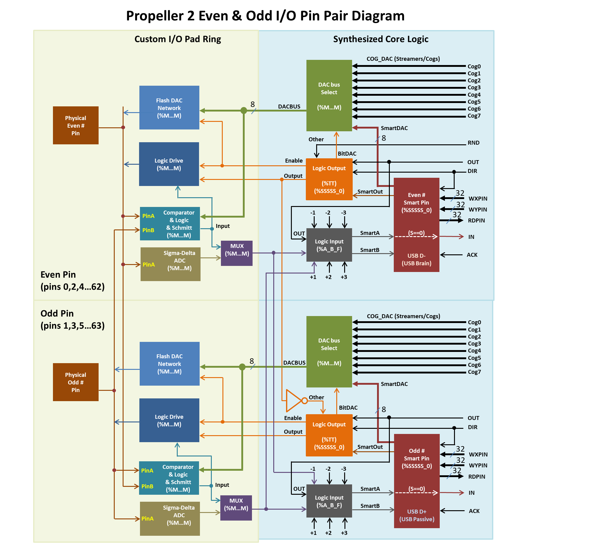
What I'd like to do is have a serial stream coming into pin X and have pin X+1 be an output that echoes pin X. The goal is to keep connections simple; pin X will be used by my program and pin X+1 will connect to a logic analyzer. I've looked though Chip's pin diagrams and tried a couple combinations that seemed workable -- but they didn't.
Any ideas?
Comments
With some PIC micros there is a CLC (Configurable Logic Cell) that you can do just what you are asking. It's atomic and doesn't require any software overhead once configured. I have used this trick to gain USART access on a port that otherwise didn't have USART access. <-- IOW ... I goofed and designed the PCB before I completely read the datasheet only to discover that the USART was not brought out to the Port I had assigned on the PCB. I was able to correct the problem in software with a CLC block. I would think that the "Smart Pins" would have a similar configuration capability.
Ozprop showed me how to do it, i'll try and find it. I think there was a trick where you needed to add an inversion. Also you can only clone the pin within its matched pair, eg make P1 follow P0, or P3 follow P2, but not P2 follow P1
A few days ago, I tried the same. I had some success with the 'Logic with Adjacent Pin Feedback' mode (no smart pin mode).
But it works only inside a pin pair (odd - even pins). So your pin X has to be an even number to get the connected output on X+1.
Andy
Unfortunately I just tried the way I was thinking, but it clones outputs but not inputs, so hopefully there's another solution
Here's the output cloning snippet,
pinhigh(57) wrpin(57, P_INVERT_OUT | P_TT_10) repeat pint(56) waitms(500)I've forgotten how a lot of this works, but maybe the P_LOGIC_B_FB mode would do it?
Yep, P_LOGIC_B_FB or P_SCHMITT_B_FB.
Also, P_SYNC_IO might want to be added so as to show on the output the internal synchronisation (registration) that occurs for the input.
Oh, and adjacent here means the pairs' partner. If your input is an even P# pin then its partner pin number is +1. If the input is an odd P# pin then its partner pin number is -1.
EDIT: So for the example above, P57's adjacent partner is P56.
I've tried this and it worked. The whole -3 to +3 pin selector has no effect here. I'm a little annoyed that the pins have to be an adjacent pair. On the P1, the counters could a bit from any pin to any other pin so long as you want it delayed by 1 clock cycle and inverted")
What I was trying to do was use the P2 comparator between 2 pins and output the signal to a 3rd pin, without a clocked flip-flop. I don't think it can do that. The comparator output is only accessible internally unless you one of the input pins to double as feedback/output. I wanted to convert a sine wave from the DDS to a square wave. DDS DAC output would go through a low-pass filter and then into the P2 comparator.
@JonnyMac If this is just temporary and the bitrate is low, you could use a spare cog for this:
Or for 4/8/16 bits at a time with some restrictions on the numbers. Won't do the +1 pin you want.
The custom pad-ring pin controls, separate from the smartpin modes, are limited to a pin pair only. If you don't mind using the comparator's internal DAC for level set then that would work. Either P_LEVEL_B_FBP (M9 low) or P_LEVEL_B_FBN (M9 high).
NOTE: All comp-DAC drive outs are 1500 ohms - A limitation of not enough M control bits to select all combinations.
NOTE2: Its DAC is quite slow and glitches on multi-bit changes. Not sure how slow. The comparator is something like 30 MHz.
An actual smartpin might be up to the job as long as you don't mind a few clock ticks of lag on the output pin. The +-3 pins of reach helps out here. There is basically only one mode that takes input from a pin and also toggles an output pin -
P_PWM_SMPS(%01010) PWM switch-mode power supply I/O. And being a smartpin, the smartA/smartB inputs can come from pin comparators too.I'm thinking power supply smartpin mode can be setup for echoing a chosen input pin. Should be able to do this by using a timebase of one sysclock tick, along with a frame period of one timebase (one sysclock tick), ie: X = $0001_0001. So the period counter will sit steady on value of one. And with Y = 1 also, the smartpin's output, smartOUT, is a steady high (while no inputs). This can be an inverted output for a steady low at the pin.
SmartB input will be the one echoed at the output. When this goes high, smartOUT goes low. And is inverted high at the pin.
SmartA input isn't needed. I'm unsure exactly what smartA actually is meant to do in terms of smartOUT. The docs aren't particularly clear.