@evanh said:
Ease up on the criticism. It's not even a safety concern at those voltages.
The criticism if it is that is mainly about the haphazard and changing specifications and overall vagueness while extolling professionalism.
However, I've had fire hazards at those currents which is a safety concern.
30Vdc at 40A is very definitely a safety concern. As Peter Jakacki pointed out, fire is one, but I'd not want to be on a wet floor with that kind of power casually running around.
This is also why we have professionals build our buildings, and they deserve their pay (and even then the roof can fall in occasionally).
I'd be also asking (perhaps they already know) things about the gauge of wire they're using, what connectors they have in mind, &c. A connector good for 40 amps at 30Vdc is not an insignificant thing.
The electrical safety aspect is fine. How commercial it becomes is his problem. We don't need to know every detail to give circuit design help. No one would be giving help on anything if we kept on down this path.
Well, to get more specific, he has said the prior design is using a CPLD wired to the transistors. That'll be at 5.0 Volts for driving the lowside, and highside drive has a natural level shift and a greater gate drive voltage. This, in turn, drives the highside harder than the low-side. Which happens to conveniently counterbalance the natural imbalance between PFET and NFET. So, there is method to his madness.
@evanh said:
Well, to get more specific, he has said the prior design is using a CPLD wired to the transistors. That'll be at 5.0 Volts for driving the lowside, and highside drive has a natural level shift and a greater gate drive voltage. This, in turn, drives the highside harder than the low-side. Which happens to conveniently counterbalance the natural imbalance between PFET and NFET. So, there is method to his madness.
PFETs have a circuit simplicity appeal, as they avoid any need of a charge pump for DC operation, and they are getting lower in RDS every year.
That said, you do still pay a premium for a same-resistance PFET over a NFET, and so you might find a good gate driver, costs less than a good-enough PFET.
For such higher power FET use, you really should use 10V gate drives.
New gate drivers like DRV8702D-Q1 and DRV8106-Q1, are rated to 47V and with charge pumps, look well suited to the OPs tasks, and they are 60-70c/1k
There are versions with more drivers per package too.
Wouldn't that imply that one or the other is at least slightly into its linear range, not fully-on? And I poked around a bit - the transistor package they suggested can dissipate 110W (given a perfect heatsink) and in a 'stuck' condition (worst case into a dead short) it's going to try to dissipate 700W. This will go 'bang' in a big way, and I, personally, don't want to be blamed when their circuit goes pop.
They're welcome to ask for help. They're welcome to keep secrets. However, we cannot help them with things we don't know about - and really don't want the blame for when things go wrong. S.
@Scroungre said:
Wouldn't that imply that one or the other is at least slightly into its linear range, not fully-on?
Which post is that relating to ?
Usually you want FETs to be 0 or 10V gate driven, so they avoid any linear range.
The simpler NPN pre-driver circuit has no protection against errant 'both on' and that fault mode is certainly an issue.
The specific gate driver ICs have internal sense elements that avoid turn on of opposing fet until the other fet has turned off, and they have UVLO checks too.
Avoids both on and partial drive faults and crow-bar currents.
Here is the P-channel AOD4185 below. It's pretty easy to see they aren't identical performance. With the NFET above using Vgs = 5.0 V and Id = 40 A then Vds is about 400 mV. With the PFET below using Vgs = 20.0 V (not graphed) and Id = 40 A then Vds might be 500 mV. The NFET with Vgs = 5.0 V still has a lower on-resistance than the PFET with Vgs = 20.0 V.
Ok with the selected components it could work.
2x AOD4184A
1x IR2104S
This would make a discrete design obsolete.
I had played with this thought because of the timing.
The voltage echo would start at 11V because of the IR2104S.
But this is also no problem.
The measurement pulse gap of 1µs in the PWM for the BACK-EMF could still be a bit tight, but in case of need 2µS would be enough.
I'll have to have a look at that on the test bench.
The gap would be, on the basis of the run times and capacities shifted, but still there. This can be measured well with the P2 ADC.
ErNa
EPC's GaN would also be a possibility, but they have a high gate capacitance which has an effect on the runtime.
jmg
A3946 I have not found any documentation for this part. But the demo board shows
already that, which overshoots the goal.
FAN3278 would also be good but its VDD is connected to the power side, so I might have problems with such a tight timing.
rogloh
A direct change of the phase from 30V to 0V or vice versa is not possible because this would cause losses.
The controller controls the power supply of the power amplifier, therefore the uncontrolled activation is impossible.
SaucySoliton
You must build for me nothing extra or risk!
What a TO252 for current tolerates depends mainly on its content.
But I have seen 20A flow through such housings.
The current consumption of the FETs will not be that big because the 1µs is the narrowest pulse of the PWM signal. Better said here all FETs are closed. The power pulses are of course a bit wider. Depending on when the maximum allowed phase current is reached.
evanh
"Use the IR2101S with two of AOD4184A" I came to the same conclusion. It does not cover all my wishes, but it fulfills the most important points.
To increase the current I would also connect two AOD4184A in parallel.
With the security guidelines I know myself so no problem.
I always cause construction stops at other companies because they simply do not follow the rules.
Peter Jakacki
"Proprietary" and "professional" sound stupid but that's what the translation program does.
That I don't publish any plans here is because I sold everything years ago and I don't have any rights anymore. I just don't want to have any trouble.
The engines are development samples there are no fixed dates. They are constantly rewound and mechanically changed.
The values U = 7,4 .... 29,6V (14,8V) and Imax = 40A (20A) are always in 001.
No a fire danger does not exist with a 4-layer printed circuit board yet, except one uses a 2-layer. Yes you have to calculate the traces otherwise it smokes.
O man so fast I can not translate everything as here everything flies in.
That the values vary somewhat is because I do not want to rebuild the part 1 to 1 but use it as a basis for a new measuring station. The währe then from me without Arger.
@Scroungre said:
30Vdc at 40A is very definitely a safety concern. As Peter Jakacki pointed out, fire is one, but I'd not want to be on a wet floor with that kind of power casually running around.
This is also why we have professionals build our buildings, and they deserve their pay (and even then the roof can fall in occasionally).
I'd be also asking (perhaps they already know) things about the gauge of wire they're using, what connectors they have in mind, &c. A connector good for 40 amps at 30Vdc is not an insignificant thing.
S.
Are 200MW turbines enough to know enough? I think so.
In most flight controllers the P-FETs are switched according to the phase position, but the N-FETs are controlled with the PWM.
The result can be heard as a squeaking noise.
Out of the question for me.
@pic18f2550 said:
jmg
A3946 I have not found any documentation for this part. But the demo board shows
already that, which overshoots the goal.
FAN3278 would also be good but its VDD is connected to the power side, so I might have problems with such a tight timing.
Here is a small interim result of my thoughts. The resistors are still outside.
Since the IR can up to 600V I think about an extension to 500V. But I still have to clarify some things.
Regarding the request for circuit diagrams and pictures of the current measuring station, there was a refusal to the circuit diagrams.
I should get some pictures next week.
And immediately he wanted to fix me with dates. Nope at the time no Bock on it. have enough work.
My fingers are tingling to install a HEXFET® Power MOSFET IRFR7540PBF right away.
With the same load as the AOD4184A, it should produce less power loss. The only question would be whether the 1µs are still reached. After all, it has twice the gate capacity.
@pic18f2550 said:
My fingers are tingling to install a HEXFET® Power MOSFET IRFR7540PBF right away.
With the same load as the AOD4184A, it should produce less power loss. The only question would be whether the 1µs are still reached. After all, it has twice the gate capacity.
MOSFETS keep coming down in mOhm.Dollar terms, and mOhm levels are in the same ballpack as direct copper traces. PCB drops can exceed FET drops.
You can now buy 1mOhm FETS for ~ 85c/1k and 550µOhm fets ~ $2/1k and 400µOhm fets ~ $3.50/1k
Bodo's Special Announcement: MOSFETs for Automotive Applications
Not an advertisment but just to give an overview to the topic. By the way: if you are using unsymmetrical PWM (one switch is PWMed, the other one only commutated in the case of a BLDC scheme) you will prefer low switching losses for the first one, low conduction losses for the second. But in the end, the design will be optimized for whatever goal you select to be important...
I know there are many ways to control a BLDC.
For me, however, the measuring points during the rotation are important to evaluate the motor.
For the control of a normal 3-phase BLDC in delta connection you need only 3 parrameters, I am at 6.


Comments
Ease up on the criticism. It's not even a safety concern at those voltages.
PS: He's translating everything written here between German, I think, and English. In both directions. It's a notable difficulty in reading.
The criticism if it is that is mainly about the haphazard and changing specifications and overall vagueness while extolling professionalism.
However, I've had fire hazards at those currents which is a safety concern.
Okay, I meant electrocution only of course. That's the unseen scary one that'll get you without any chance of escape.
There is untold machine control safety concerns for everyone. The roof can fall in too.
The apparent haphazardness is because he can't read or write English.
30Vdc at 40A is very definitely a safety concern. As Peter Jakacki pointed out, fire is one, but I'd not want to be on a wet floor with that kind of power casually running around.
This is also why we have professionals build our buildings, and they deserve their pay (and even then the roof can fall in occasionally).
I'd be also asking (perhaps they already know) things about the gauge of wire they're using, what connectors they have in mind, &c. A connector good for 40 amps at 30Vdc is not an insignificant thing.
S.
The electrical safety aspect is fine. How commercial it becomes is his problem. We don't need to know every detail to give circuit design help. No one would be giving help on anything if we kept on down this path.
Specs and links are not affected by translation although he doesn't seem to have a problem stating the proprietary nature of the project.
Well, to get more specific, he has said the prior design is using a CPLD wired to the transistors. That'll be at 5.0 Volts for driving the lowside, and highside drive has a natural level shift and a greater gate drive voltage. This, in turn, drives the highside harder than the low-side. Which happens to conveniently counterbalance the natural imbalance between PFET and NFET. So, there is method to his madness.
PFETs have a circuit simplicity appeal, as they avoid any need of a charge pump for DC operation, and they are getting lower in RDS every year.
That said, you do still pay a premium for a same-resistance PFET over a NFET, and so you might find a good gate driver, costs less than a good-enough PFET.
For such higher power FET use, you really should use 10V gate drives.
New gate drivers like DRV8702D-Q1 and DRV8106-Q1, are rated to 47V and with charge pumps, look well suited to the OPs tasks, and they are 60-70c/1k
There are versions with more drivers per package too.
Wouldn't that imply that one or the other is at least slightly into its linear range, not fully-on? And I poked around a bit - the transistor package they suggested can dissipate 110W (given a perfect heatsink) and in a 'stuck' condition (worst case into a dead short) it's going to try to dissipate 700W. This will go 'bang' in a big way, and I, personally, don't want to be blamed when their circuit goes pop.
They're welcome to ask for help. They're welcome to keep secrets. However, we cannot help them with things we don't know about - and really don't want the blame for when things go wrong. S.
Which post is that relating to ?
Usually you want FETs to be 0 or 10V gate driven, so they avoid any linear range.
The simpler NPN pre-driver circuit has no protection against errant 'both on' and that fault mode is certainly an issue.
The specific gate driver ICs have internal sense elements that avoid turn on of opposing fet until the other fet has turned off, and they have UVLO checks too.
Avoids both on and partial drive faults and crow-bar currents.
Yes and no. Fully-on has its variability still. The parts listed are rated for 4.5 Vgate.
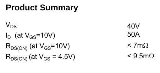
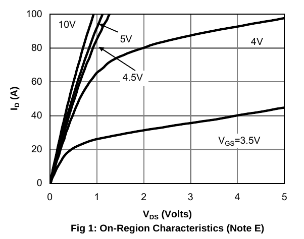
That was the N-channel AOD4185A above.
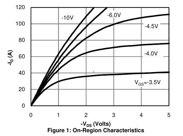
Here is the P-channel AOD4185 below. It's pretty easy to see they aren't identical performance. With the NFET above using Vgs = 5.0 V and Id = 40 A then Vds is about 400 mV. With the PFET below using Vgs = 20.0 V (not graphed) and Id = 40 A then Vds might be 500 mV. The NFET with Vgs = 5.0 V still has a lower on-resistance than the PFET with Vgs = 20.0 V.
Ok with the selected components it could work.
2x AOD4184A
1x IR2104S
This would make a discrete design obsolete.
I had played with this thought because of the timing.
The voltage echo would start at 11V because of the IR2104S.
But this is also no problem.
The measurement pulse gap of 1µs in the PWM for the BACK-EMF could still be a bit tight, but in case of need 2µS would be enough.
I'll have to have a look at that on the test bench.
The gap would be, on the basis of the run times and capacities shifted, but still there. This can be measured well with the P2 ADC.
ErNa
EPC's GaN would also be a possibility, but they have a high gate capacitance which has an effect on the runtime.
jmg")
A3946 I have not found any documentation for this part. But the demo board shows
already that, which overshoots the goal.
FAN3278 would also be good but its VDD is connected to the power side, so I might have problems with such a tight timing.
rogloh
A direct change of the phase from 30V to 0V or vice versa is not possible because this would cause losses.
The controller controls the power supply of the power amplifier, therefore the uncontrolled activation is impossible.
SaucySoliton
You must build for me nothing extra or risk!
What a TO252 for current tolerates depends mainly on its content.
But I have seen 20A flow through such housings.
The current consumption of the FETs will not be that big because the 1µs is the narrowest pulse of the PWM signal. Better said here all FETs are closed. The power pulses are of course a bit wider. Depending on when the maximum allowed phase current is reached.
evanh
"Use the IR2101S with two of AOD4184A" I came to the same conclusion. It does not cover all my wishes, but it fulfills the most important points.
To increase the current I would also connect two AOD4184A in parallel.
With the security guidelines I know myself so no problem.
I always cause construction stops at other companies because they simply do not follow the rules.
Peter Jakacki
"Proprietary" and "professional" sound stupid but that's what the translation program does.
That I don't publish any plans here is because I sold everything years ago and I don't have any rights anymore. I just don't want to have any trouble.
The engines are development samples there are no fixed dates. They are constantly rewound and mechanically changed.
The values U = 7,4 .... 29,6V (14,8V) and Imax = 40A (20A) are always in 001.
No a fire danger does not exist with a 4-layer printed circuit board yet, except one uses a 2-layer. Yes you have to calculate the traces otherwise it smokes.
O man so fast I can not translate everything as here everything flies in.
That the values vary somewhat is because I do not want to rebuild the part 1 to 1 but use it as a basis for a new measuring station. The währe then from me without Arger.
Are 200MW turbines enough to know enough? I think so.
The linear range is traversed at each switching state.
It is therefore important that this happens as quickly as possible.
In most flight controllers the P-FETs are switched according to the phase position, but the N-FETs are controlled with the PWM.
The result can be heard as a squeaking noise.
Out of the question for me.
A download link to datasheet shows here ?
https://www.allegromicro.com/en/products/motor-drivers/bldc-drivers/a3946
The FAN3278 thresholds are TTL so do not vary (much) with Vdd. Says 1.8V/1.1V typical Schmitt thresholds.
Huh, no full-bridge example in the datasheet.
I don't sign NDAs, period. I like keeping my toolbox of skills and methods intact for serving other customers.
-Phil
I think that's part of good manners for a business project. In my private life, I'm just as interested as if a sack of rice falls over in China.
Here is a small interim result of my thoughts. The resistors are still outside.
Since the IR can up to 600V I think about an extension to 500V. But I still have to clarify some things.
Regarding the request for circuit diagrams and pictures of the current measuring station, there was a refusal to the circuit diagrams.
I should get some pictures next week.
And immediately he wanted to fix me with dates. Nope at the time no Bock on it. have enough work.
And first have a nice weekend.
---- EDIT 2021.05.17 -----------------------------------------------------------
Incorrect display
The schematic is incorrect - truth table and pins 2 & 3 on the IC.
I just noticed that too. I'll change it on Monday on the PC.
I don't have an Eagle on my smart.
The grandchildren have been grumbling a bit.
My fingers are tingling to install a HEXFET® Power MOSFET IRFR7540PBF right away.
With the same load as the AOD4184A, it should produce less power loss. The only question would be whether the 1µs are still reached. After all, it has twice the gate capacity.
MOSFETS keep coming down in mOhm.Dollar terms, and mOhm levels are in the same ballpack as direct copper traces. PCB drops can exceed FET drops.
You can now buy 1mOhm FETS for ~ 85c/1k and 550µOhm fets ~ $2/1k and 400µOhm fets ~ $3.50/1k
Bodo's Special Announcement: MOSFETs for Automotive Applications
Not an advertisment but just to give an overview to the topic. By the way: if you are using unsymmetrical PWM (one switch is PWMed, the other one only commutated in the case of a BLDC scheme) you will prefer low switching losses for the first one, low conduction losses for the second. But in the end, the design will be optimized for whatever goal you select to be important...
I know there are many ways to control a BLDC.")
For me, however, the measuring points during the rotation are important to evaluate the motor.
For the control of a normal 3-phase BLDC in delta connection you need only 3 parrameters, I am at 6.
In various forums, the IR2104S is referred to as the FET killer.
What strikes me are the following points:
The doc does state the maximum output strokes, but I can't find the reference in the doc.
The inserted gate resistors cause a flattening of the switching edges. This has the consequence that:
To avoid this, the signal SD could be deactivated for a short time before the edge change.
I could also have translated the documentation incorrectly and not solve the problem.