

P2 Power amplifier
 pic18f2550
Posts: 400
pic18f2550
Posts: 400
Hello,
I need a little more power to the P2 pinns.
I have thought of something.
Does anyone know about this?
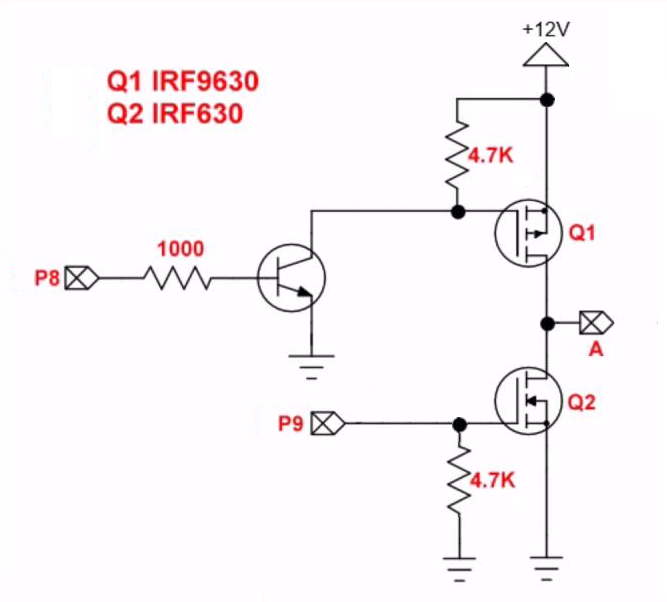
U = 7,4 .... 29,6V (14,8V)
Imax = 40A (20A)
The FET is probably something like "STB60NF06LT4".
But I have to search a little bit.
At the gate of the T2 I have no resistor. Is that OK for the P2 or must there be one?
---- EDIT 2021.05.17 -----------------------------------------------------------
So simply nailing the old circuit to the P2 doesn't work.
I think that would be better.
Comments
Now there is a risk of short circuit and a magic smoke release if you accidentally set both pins high. Use one more inverter transistor and only one pin to control this, to avoid opening both power transistors at once.
I need 3 switching states H, L and tristate.")
In the 0V line there is a current measuring resistor, which blocks the L FETs in case of a short circuit or overcurrent.
During the development phase everything is connected to a laboratory power supply.
We need to get the generic BLDC motor board done. It would do all these things.
Always have an Rgate resistor. And put a protective zenor (TVS) beside the 4k7 resistor too. The capacitive back feed can be rough.
There are very nice SOIC-8 half-bridge MOSFET drivers available from TI and Microchip which allow NFETs to be used as both the high and low switches.
Ok, I can see the resistance is needed.
If I have understood correctly, pulses can reach the P2 from the power side via the gate capacitance.
Let's see how I can block them.
Shotky diodes against GND are no problem.
But against the 3.3V they are.
Maybe a z-diode of 5V to the gate of Q2.
I'm not so worried about the driver transistor of Q1, it should be able to handle it.
Up to 60A?
Do you have a type number for me?
Chip is talking about NFET drivers, not the power transistors, that provide a simpler board when using NFETs on both the high and low sides. They have a built-in charge pump circuit that gives an extra supply rail above the V+ bus.
If you want 20-40A, that's going to be tricky direct from the 3.3V levels of P2, as most high current MOSFETS prefer ~10V gate drive
As Chip mentioned there are SO8 gate driver parts, but most low cost ones use a bootstrap cap, which limits the upper N-FET drive to < 100%.
As evanh mentions, there are also more complex charge-pump-included gate drivers, that have lockout and crow-bar protections.
Allegro A3946 is one example.
Less common, are PFET-NFET gate drivers like FAN3278, which could work with this Vishay PFET
I find that if you are talking 60A and asking for a "type number" then you may be out of your depth and need a lot more than just a simple type number. If you want help then rather than posting a circuit which btw will probably end badly with lots of smoke, just describe what you are trying to do with as much information as you can such as the type of load including part numbers, the frequency, any speed control, etc. I've done many high power circuits and it is very very easy to make them smoke or fail prematurely.
If you find that the best solution is a rock, then why use transistors? The point of that is don't try to specify the solution before understanding the problem.
If you just want on/off, may I suggest a relay or two? S.
Another way to design it is to have the two P2 control pins being a tri-state signal and high/low output select signal instead of manual control of each FET. Then if your high/low FET gate control circuit is designed such that at the transition point it doesn't ever turn both FETs on at the same time (ie. it has a dead-band in the middle), you won't be able to short it out by mistake from the P2 output pin combinations. Turning on/off the large load current this way with a tri-state signal may create voltage spikes if it's inductive though. You'll probably want some suitable diode protection on the output. Or just use a chip that is designed for this type of purpose as suggested.
There are chips that have a 3-state pin PWM sense, so H,L drive fets and HiZ gives diode emulation, which floats to both off, once any current reverses.
That would allow a single P2 pin to control the power elements.
Yes that is the safer way to go. I really don't like the idea that a random output pattern on the P2 pins by mistake could have both FETs on at the same time. You can easily strap the tri-state control pin in a way that the P2 boots with FETs off until the P2 software is fully ready to drive the output.
The AMX4 portable xray machine uses a similar circuit but with a 120vdc supply. Detailed prints aren't hard to find. The design uses an opto coupler on both phases driving the FETs so that if there is an event that punches through the gate, you don't apply 12v to your P2.
The other item of note is the pulses are conditioned such that they can not overlap on times. You could accomplish that with oneshots in hardware or appropriate delay times in software for the rise and on time.
That system has a number of good example circuits worth co-opting for projects. Nothing really special or off the wall, but ztill a very bullet proof system for its age.
Ok, I'll have a little chat about that.
I want to modernise my somewhat outdated control system for my 5-pole linear motor.
The controller still works with several MACH435s.
At that time I had designed the circuit for 20A phase current.
A short circuit is no problem as the power supply takes over the limitation.
The motor has a very low inductance. 7 windings per pole.
The PWM period is 1 µs.
Translated with www.DeepL.com/Translator (free version)
So you need 5 copies of this driver ?
What interface do you use now, between the power FETs and the MACH543's ?
Do you have the MACH543's doing any fast protection ?
The adjustment is made with HF transistors.
So no risk for the MACH.
I was just thinking about using an OPV (comparator) as a driver.
I just have to find one with a high transit frequency and gain.
I'm not quite following ?
If you have a already working and proven system using MACH plds, you just need to remove the MACH's and drop in P2.
What logic swing does the MACH give - FWIR, most 5V CPLDs used a NMOS TTL Style output, which means they do not drive to 5V, but have VOH ~ 3.5V
At the worst you just need a CMOS buffer / lever translator, and there are a lot of those for 3v3 to 5V interface. Just pick how many bits you need, or sprinkle single-gate ones, if that makes PCB design easier.
Well, I don't want it to be that simple.
I could have done that with half a P1.
After all, the P2 has a lot of hardware that I want to have from the discreet area.
So I want to replace the simple comparators with 7bit ADCs.
I also want to replace the simple triangular signal curves with a sinusoidal one.
This should result in much better values.
Any product information on this? Links?
Do you have a schematic of that?
Do you have product information on that? What is the trip point and what is the short-circuit current limited to etc?
Do you mean that the PWM frequency is 1MHz? What is the reasoning there?
How many bits of resolution do you need?
Working with 1MHz PWM certainly can not be done without a carefully designed driver as the timing is very critical. 1 µs period and 1% resolution of the PWM means we are in the range of a few nano seconds. That's no childrens play. By the way: Peter, do you check your inbox ;-)
Driving a 20A capable mosfet at 1MHz is going to take a lot of current. Even if 3.3v was enough, the P2 pins won't have enough current. Perhaps 600mA average current. Driver dissipation would be 7.2W, way more than an SO8 would handle. The datasheets for some gate drivers explain how to calculate the power required. This might be a good application for some of EPC's gallium nitride fets. I want to try some, but not sure if I could do the soldering.
I'm working on a board with 3 half bridges right now. The input power is 40v, 10a. Maybe it could handle 20a. But not at 1MHz. The max I run is 150kHz.
Anyone know how much current a TO252 can handle under conservative engineering rules?
EPC´s GaN as a test unit would be great. I thought about using them but didn't come further. Such a power board would allow to control laser diodes or similar, to break frontiers.
"Is there any product information on this? Links?"
No, the motors are our own designs.
"Do you have a circuit diagram of it?"")
Yes, but I will not put it on the net, because I need the things professionally and I don't want to cut off my water.
"Do you have any product information on it? What is the trip point and what is the short circuit current limited to, etc.?"
The power supply is a proprietary development.
In principle, between SV and driver is almost no capacity.
Switched off at 40A pulse peaks.
However, the P2 will soon take over this.
"Do you mean that the PWM frequency is 1MHz? What is the rationale for this?"
I also have ironless motors here is a fast response needed.
Here the current consumption is between 1 - 12A.
For the slightly larger ones, I could also move the PWM period just below 500Khz.
But for test purposes 1Mhz would be an interesting topic.
"How many bits of resolution do you need?"
The PWM resolution is not so important because I monitor the BACK-EMF voltages for phase. (here 4 bits would be even enough)
In full load operation the motors are operated like synchronous motors.
I've picked out a few times to see if that works.
A CD4007 could be used as a driver.
With the PFET driver there, you could use a resistor in the NPN emitter, that has some advantages :
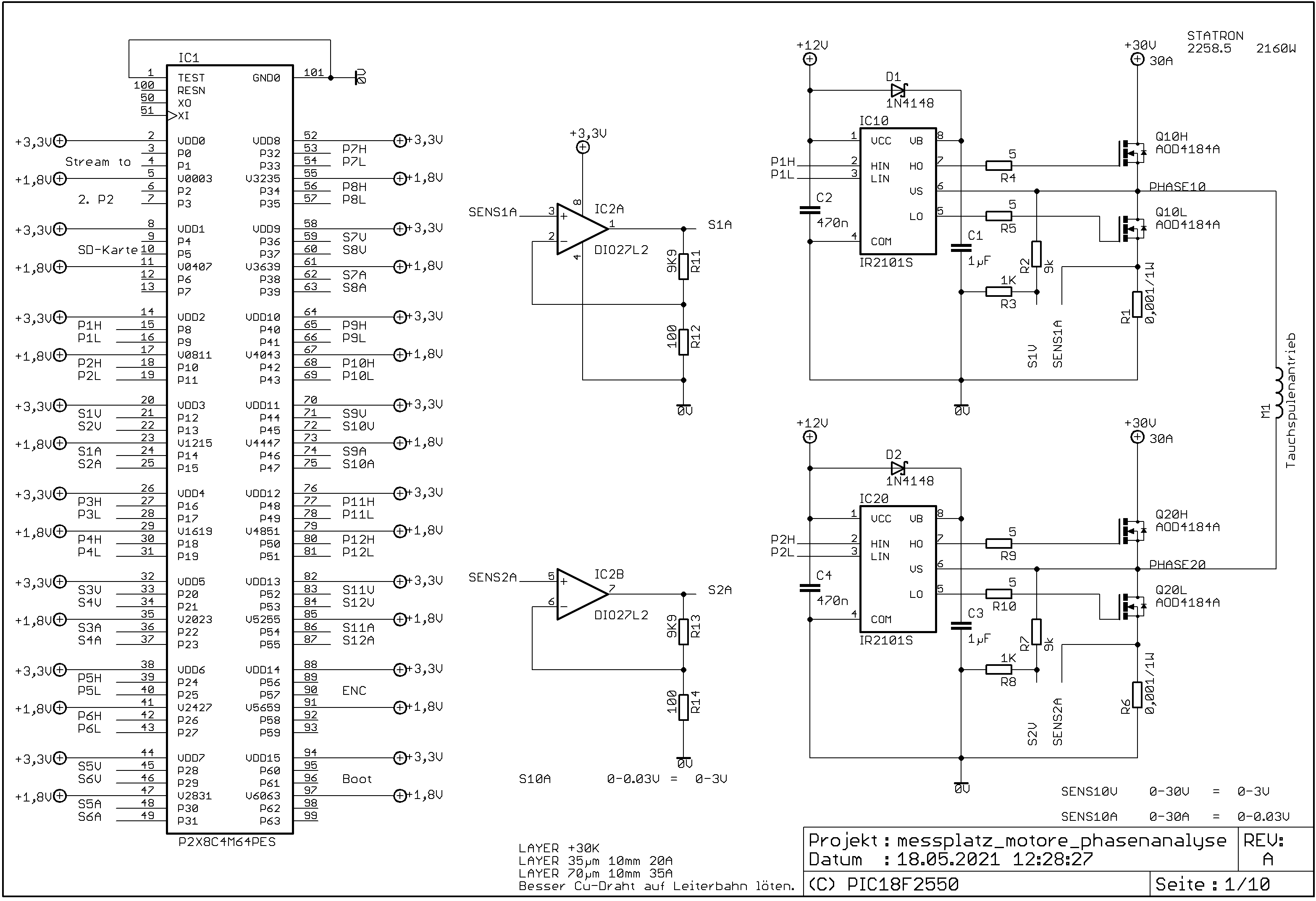
It looks to me like you're going to have to use a driver circuit with voltage translation because the Prop2's 3.3 volt outputs are not at all sufficient for lowside drive. May as well go the whole hog and do the highside as an NFET as well, ie: Use the IR2101S with two of AOD4184A.
I drafted this yesterday but in light of other comments, here goes...
You use the words "proprietary" and "professional", and for these reasons you can't reveal much yet you are asking for help on a public forum?
Those transistors you selected might sound like they would cut it but the package probably won't be able to handle the continuous power. Anyway, look at the charts and you will see that you really need 10V drive to ensure the transistors are fully on (otherwise Rds(on) is higher = heat --> smoke). Also NCH have better specs than PCH and all you need is high-side drive.
Once again, while that circuit you show is essentially the "interweb basics", it is a bit too basic and you also have to take into account your load. However all your posts seem to have different figures and requirements and after all that, what is the PWM frequency that you have been using?
If you have a specific requirement then you can specify it, as to what that voltage is and how much current it needs to handle continuously etc. Now I see the supply has jumped to 30V, not 12V.
Your statement quoted here tells us nothing and is confusing:
Sounds like you haven't designed anything like this before and none of this looks professional at all. In light of that if you want help, then don't ramble on about part numbers,, just be clear, concise, and precise in stating and specifying your requirements, just as you would expect a customer to do who comes to you and needs help, and so then we might be able to help you.
Or hire a real professional who does actually know what they're doing.
Also you can have them sign an NDA - Non-Disclosure Agreement - that says they're not allowed to tell anyone else about your circuits, so you don't have to worry about them being stolen. S.
Eta: Yes, some of us do know what we're doing. No, we're not going to sign an NDA for free.