This is great work Ltech. Perfect equipment to tune it. If those colour levels are optimized it should be spot on. The PAL colour bars already looks like it causes the vectors to line up pretty well in the boxes. I imagine it is designed to be correct when it is properly terminated with 75 ohms.
Yes, this is "high grade" broadcast calibration tool of my work.
This is used to do color shading (color grading) on live broadcast events.
The marks are calibrated
I know, with experience, this looks as good color encoding, but the levels are wrong.
-I do not be sure anymore about the color bar image I use in the prop.
My original is a calibrated image, but after reducing and adapt it to .bmp and size to get it to the P2, I am not sure anymore.
I do not know how to re calibrate/mesure it.
-I am not sure about the video output impedance of the AV circuit of the P2.
It is the standard AV plugin. The international standard of video termination is alway 75 Ohm and a video level of 1 volt top-top
I see the black level is 0.05 volt tho high to.
I go try to get an calibrated "analogue" color bars generator to compare with the P2
I only use the breadboard and assume we have lot of parasite influences.
@Ltech said:
-I am not sure about the video output impedance of the AV circuit of the P2.
It is the standard AV plugin. The international standard of video termination is alway 75 Ohm and a video level of 1 volt top-top
It's meant to be a 2 V DAC in the P2 with 75 output impedance, and therefore able to drive 1V into a 75 ohm load, so I'm surprised you are seeing issues there, unless the output levels were setup wrong in the code or something.
My expectation of the color bars are wrong.
The AV plugin board has only a serial capacity between the pin and the RCA plug.
The sync level has do decreases to -0.3 Volt, now it is -1.8 Volt
the levels are close
@Ltech said:
And with DC restore off .... lot of dc jitter
There is a an optional capacitor in series with the composite RCA output for audio purposes that can be switched on or off with the DIP switches on the A/V breakout board. It is enabled if the switch is in the OFF position for that RCA channel. Maybe you had it enabled and the DC levels are wandering. The P2 doesn't generate negative voltage levels however so it is going to come out as 0-1V, not -0.3 to 0.7V if you were expecting that.
The minus volt coming from the mind, black is 0 no light. It is the reference on video.
The sync is expected to be 0.3 volt below of the black.
I do not believe this is an issue, the sync is taken halfway between max and min sync.
Everything below black is called supper black and are not visible on a screen.
For the AV board I understand the dip switch bypass the capacitor ?
If the switch is set to OFF, there is a capacitor in series. If the switch is ON the capacitor is bypassed and pure DC comes out the composite RCA jack from the P2.
That seems to explain why you have jitter with the switches OFF.
I believe you should be testing in the 3rd picture case above. Terminated with 75 ohms, and switches ON.
I wonder if these numbers are increasing the white level too high? I think the official thing is to have 100 IRE units above the blank level as the peak white level, but the numbers above seem to imply peak white is 140 units above. This might be why things seem so bright/oversaturated unless some other scaling is somehow compensating for this. Maybe this was to try to increase the dynamic range of the DAC a bit and shrink the syncs to be a smaller proportion of the range, but perhaps that has a negative effect here?
It would be good to get this perfectly tuned, or as best as the P2 can deliver, so there would hopefully be less variation in what different monitors show with a given composite or s-video output signal from the P2.
"p_channel" is another predefined constant, just like "p_dac_75r_2v" is. It's needed for the streamer to drive the DAC. I call it the COG_DAC mode in the I/O block diagram.
It's obscure meaning is, when in DAC_MODE, and when not using a smartpin, it enables one 8-bit cog/streamer DAC channel into that DAC.
@cgracey said:
All the numbers I used in those CON sections came from NTSC and PAL descriptions. Unless the descriptions were wrong, it should be all correct.
Most of it seems right but the thing is Chip, with your numbers above it looks like you are adding 140 units to the blank level to reach peak white, on top of the 40 units (NTSC) or 43 (PAL) for sync. I understand it is only meant to be 100 units from the blank to the peak white, not 140. Here's an NTSC definition here.
Due to the other scaling and the colour space levels it might have only have the effect of shrinking the sync tips, but I'm not 100% sure it won't affect the other amplitudes somehow - it's scaling upon scaling with all this stuff and difficult to figure out. However if the colour burst amplitude is not right then colour may be affected.
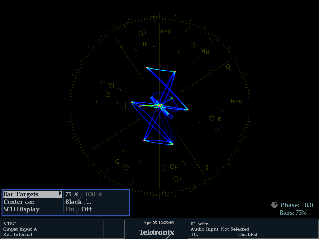
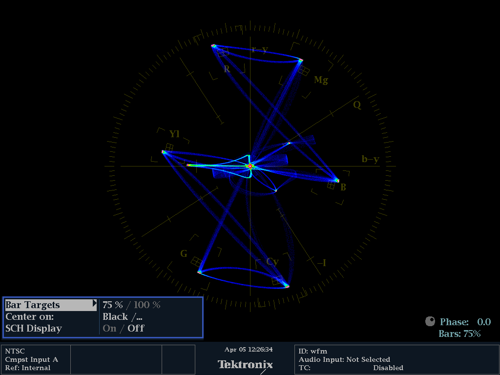
LTech's PAL captures are showing the sync height is 0.15V instead of 0.3V, and the colour burst amplitude is 0.1V instead of 0.14. I think this could explain why the colour saturation is a bit off. Ltech's latest posted picture is showing what PAL should look like on the tester with 75% colour bars with a reference generator. In comparison the P2 is putting out what was shown directly below the "AV switches on and 75 ohm" case in the post prior and you can see it is a bit different. They really should be the same (or very close).
@Ltech said:
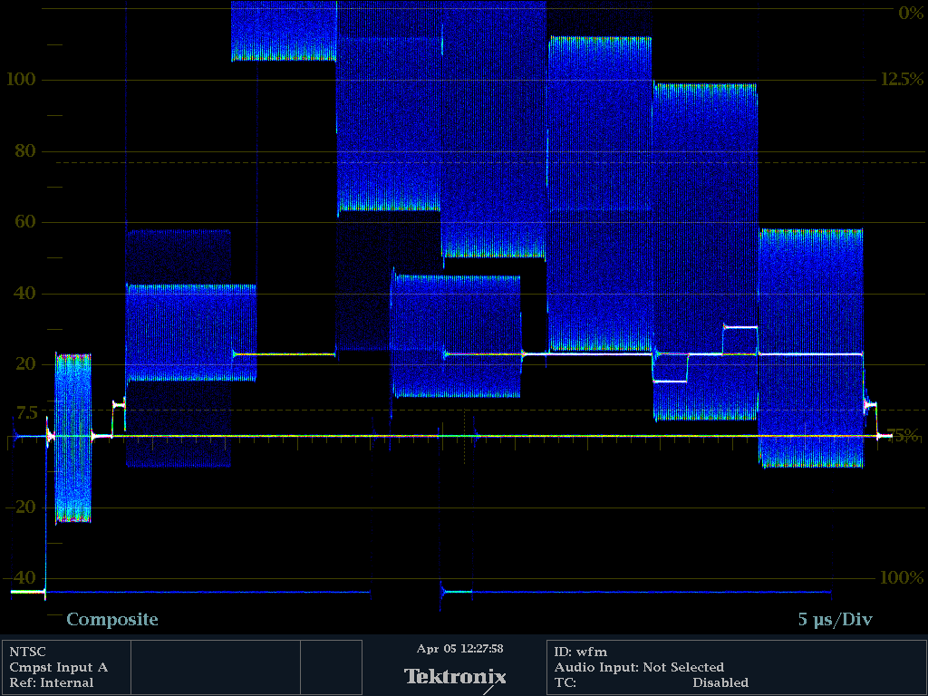
I get the chroma good if I have no termination 75 Ohm
I get the luma good is I have termination.
I believe this is because the Chroma burst level is too low when correctly terminated with 75 ohms. By not terminating it you are amplifying the colour burst to close to what it should be but this will then overdrive the Luma. These colour levels are not optimal yet but I'm confident we'll figure it out in the end. Phase looks okay though, right? I think the reference colours need scaling up to 0.14V amplitude, then your vectorscope will show better levels.
Probably these values need adjusting.
ntsc_cb         = $809000_01                            'colorburst reference color
pal_cb          = $FFC060_01                            'colorburst reference color
You can see in the reference generator output what those two traces at 135 degrees and 225 degrees are doing, they are set nicely at those marks on the vectorscope screen. We need the P2 to be close to that for PAL. For NTSC it is at 180 degrees, and is too small as well with 75 ohm termination. See top image on this page.
When I put pal_scale_cor == 1 then I get more chroma but also more burst level.
A lot of this is inter-related, it needs to be set just right. It's mostly right already but we need to boost the colour burst levels first, then I'm hoping we'll be pretty good.
@Ltech
I think what Chip might have done with the 140 vs 100 IRE unit range was to expand the headroom to ensure that the full RGB colour range from 0-255 will not exceed the DAC range and cause it underflow. However it seems to have affected the colour burst levels and sync levels somewhat. I'm playing about with the values on the scope at the moment. I found the sync height can be extended to 0.3V by making the height 76 (0.3 * 255). The PAL colourburst level can be increased by making a change to the pal_cb value. These changes may affect the range and some colours may still underflow...TBD.
Try these modifications separately or together if you get a chance to see if it improves the PAL levels with your 75% test pattern on the vector scope (terminated with the 75 ohms and DIP switch = ON). I'm still looking at it myself, as well as what NTSC is doing.
Still not perfect but definitely getting a bit closer now @Ltech . We'll get there and I'm still working on the colourspace converter gain in the chroma path which will fix the colour levels in the vectorscope. For the colours to come out right we need this to match the reference generator.
In the end I think to do it properly and avoid problems with 100% cyan levels exceeding 1V we may wish to capacitively couple the chroma to the luma externally from the Y/C output. 470pF might be our friend for a cheap solution. The other way is not to use the full RGB range in software (not good), or to scale 100% RGB colours to work as 75% only by reducing them down in the colourspace converter and live with that level of saturation.
That is the crux of the problem here, the 1V video DAC headroom, because some fully saturated RGB colours can exceed the 1V output and then wrap around to mess up the colour (I've seen this on the scope, 100% Cyan gives you 0.491V of luminance out of the 0.7V and 0.885Vp-p of chroma, which together exceed 1V with the 0.3V sync included). I think Chip has shrunk the sync tips down from 0.3V to 0.15V to try to buy a bit more headroom above the 0.7V peak white for this reason, but despite that effort the levels are still not right.
I also took a look inside your .bmp test pattern file with your colour bars. You are using the NTSC 75% level as your white, while the PAL reference is using 100% (for white) and 75% for all its coloured bars. Your bmp file uses $C00000, $00C000, $0000C0, etc as the RGB values in its palette table for the different colours which is close for 75% so I think it's an OK value. I have been using $BF myself as 255*0.75 = 191.25, meaning 191 ($BF) is a little closer to the value than 192 ($C0).
@rogloh said:
or to scale 100% RGB colours to work as 75% only by reducing them down in the colourspace converter and live with that level of saturation.
Most decoders seem to determine saturation relative to the color burst, so as long as the burst is as wrong as the actual colors are, everything is fine.
If that's true we could just scale the 100% colour down to 75% colour levels and also reduce the colour burst to not exceed the DAC range. It won't match the reference but it will fit the DAC range. i.e. go back to Chip's current solution and live with the reduced chroma levels as shown in the top picture of this page.
@rogloh said:
If that's true we could just scale the 100% colour down to 75% colour levels and also reduce the colour burst to not exceed the DAC range. It won't match the reference but it will fit the DAC range. i.e. go back to Chip's current solution and live with the reduced chroma levels as shown in the top picture of this page.
You don't reduce the burst, since it is also affected by the modulation level. If you reduce both you get too much saturation.
Yeah I might try it too. Lachlan and I were discussing this over the phone earlier today as an option. I think it might introduce a little bit of pixel phase shift between luma and chroma at 470pF (which has an impedance of around 76 ohms for the PAL colour frequency) but with TV filtering it probably isn't that noticeable. Other value caps may be better and introduce less shift. Those cheap cables that convert SVideo to composite would just use a capacitor in the connector housing.
Just looking at a picture now. It worked with the 470pF between Luma and Chroma output pins. Composite lead attached to the Luma side pin. I still need to boost the levels for the colour bar test pattern up to the correct levels and prove it works fully. My (current) hacked settings were these.
I was thinking some more, what matters is the phase difference between colorburst and video signal bursts, and all that would be equally affected by whatever capacitor value, so it cancels out. As your link points out 400pF to 10nF (and probably beyond) should be fine


Comments
NTSC
With calibrated 75 Ohm
No 75 Ohm
With 75 Ohm
No 75 Ohm
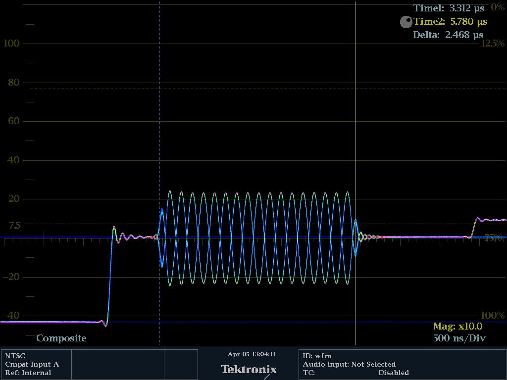
timing and no 75 Ohm termination:
This is great work Ltech. Perfect equipment to tune it. If those colour levels are optimized it should be spot on. The PAL colour bars already looks like it causes the vectors to line up pretty well in the boxes. I imagine it is designed to be correct when it is properly terminated with 75 ohms.
Yes, this is "high grade" broadcast calibration tool of my work.
This is used to do color shading (color grading) on live broadcast events.
The marks are calibrated
I know, with experience, this looks as good color encoding, but the levels are wrong.
-I do not be sure anymore about the color bar image I use in the prop.
My original is a calibrated image, but after reducing and adapt it to .bmp and size to get it to the P2, I am not sure anymore.
I do not know how to re calibrate/mesure it.
-I am not sure about the video output impedance of the AV circuit of the P2.
It is the standard AV plugin. The international standard of video termination is alway 75 Ohm and a video level of 1 volt top-top
I see the black level is 0.05 volt tho high to.
I go try to get an calibrated "analogue" color bars generator to compare with the P2
I only use the breadboard and assume we have lot of parasite influences.
It's meant to be a 2 V DAC in the P2 with 75 output impedance, and therefore able to drive 1V into a 75 ohm load, so I'm surprised you are seeing issues there, unless the output levels were setup wrong in the code or something.
My expectation of the color bars are wrong.
The AV plugin board has only a serial capacity between the pin and the RCA plug.
The sync level has do decreases to -0.3 Volt, now it is -1.8 Volt
the levels are close
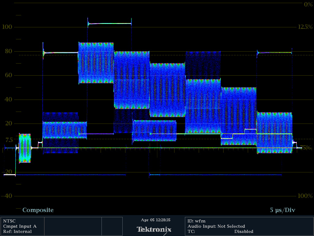
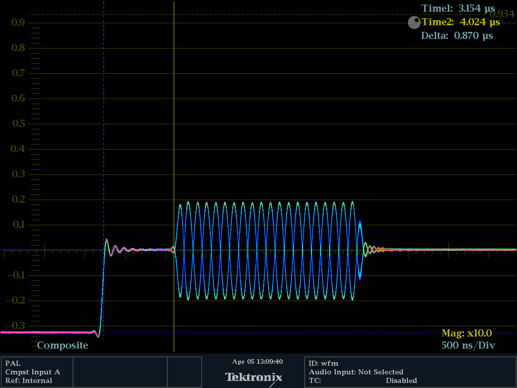
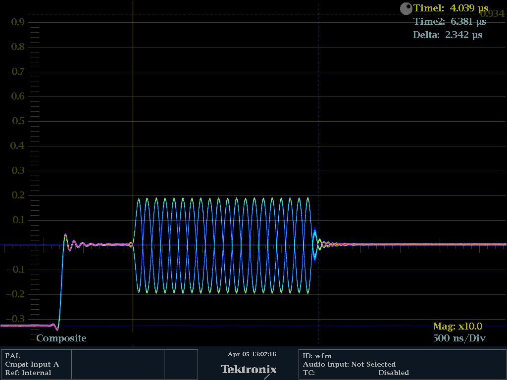
Color bar only luma with 75 Ohm:
Color bar only chroma with 75 Ohm:
And with DC restore off .... lot of dc jitter
Yep, the luma level is waaay high, I've noticed that, too.
There is a an optional capacitor in series with the composite RCA output for audio purposes that can be switched on or off with the DIP switches on the A/V breakout board. It is enabled if the switch is in the OFF position for that RCA channel. Maybe you had it enabled and the DC levels are wandering. The P2 doesn't generate negative voltage levels however so it is going to come out as 0-1V, not -0.3 to 0.7V if you were expecting that.
The minus volt coming from the mind, black is 0 no light. It is the reference on video.
The sync is expected to be 0.3 volt below of the black.
I do not believe this is an issue, the sync is taken halfway between max and min sync.
Everything below black is called supper black and are not visible on a screen.
For the AV board I understand the dip switch bypass the capacitor ?
Strange ? got more jitter when terminated and switches off (= opposite of vga connector direction)
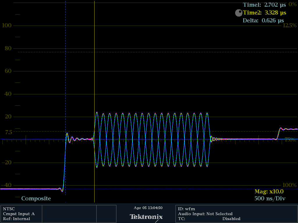
AV switches off, clamping off on Tektronix, no 75 Ohm
Same with 75 Ohm
AV switches on and 75 Ohm
AV on, and no 75 Ohm
If the switch is set to OFF, there is a capacitor in series. If the switch is ON the capacitor is bypassed and pure DC comes out the composite RCA jack from the P2.
That seems to explain why you have jitter with the switches OFF.
I believe you should be testing in the 3rd picture case above. Terminated with 75 ohms, and switches ON.
Looking at the accessory board I see the ON positions are labelled VIDEO with the OFF positions label AUDIO.
Looking at Chip's code, I see these levels
and
I wonder if these numbers are increasing the white level too high? I think the official thing is to have 100 IRE units above the blank level as the peak white level, but the numbers above seem to imply peak white is 140 units above. This might be why things seem so bright/oversaturated unless some other scaling is somehow compensating for this. Maybe this was to try to increase the dynamic range of the DAC a bit and shrink the syncs to be a smaller proportion of the range, but perhaps that has a negative effect here?
It would be good to get this perfectly tuned, or as best as the P2 can deliver, so there would hopefully be less variation in what different monitors show with a given composite or s-video output signal from the P2.
All the numbers I used in those CON sections came from NTSC and PAL descriptions. Unless the descriptions were wrong, it should be all correct.
I get the chroma good if I have no termination 75 Ohm
I get the luma good is I have termination.
So how do I get more chroma level, and not change the luma level
Y = Luma
U and V are the chroma in PAL.
=>
pal_scale_coris the scale factor of the Chroma?When I put pal_scale_cor == 1 then I get more chroma but also more burst level.
I do not understand the value of
dacmode long p_dac_75r_2v+p_channelI see "75r" and "2v"
I use real quality BNC labels and plugs
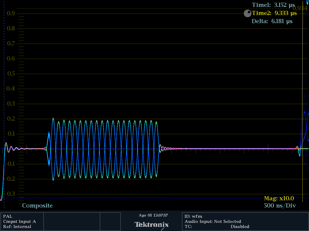
With a reference Analogue pal generator I get this pictures with the same WFM7100 and cable and termination.
"p_channel" is another predefined constant, just like "p_dac_75r_2v" is. It's needed for the streamer to drive the DAC. I call it the COG_DAC mode in the I/O block diagram.
It's obscure meaning is, when in DAC_MODE, and when not using a smartpin, it enables one 8-bit cog/streamer DAC channel into that DAC.

Most of it seems right but the thing is Chip, with your numbers above it looks like you are adding 140 units to the blank level to reach peak white, on top of the 40 units (NTSC) or 43 (PAL) for sync. I understand it is only meant to be 100 units from the blank to the peak white, not 140. Here's an NTSC definition here.
https://www.nutsvolts.com/magazine/article/video_basics
Also
https://en.wikipedia.org/wiki/IRE_(unit)
Due to the other scaling and the colour space levels it might have only have the effect of shrinking the sync tips, but I'm not 100% sure it won't affect the other amplitudes somehow - it's scaling upon scaling with all this stuff and difficult to figure out. However if the colour burst amplitude is not right then colour may be affected.
LTech's PAL captures are showing the sync height is 0.15V instead of 0.3V, and the colour burst amplitude is 0.1V instead of 0.14. I think this could explain why the colour saturation is a bit off. Ltech's latest posted picture is showing what PAL should look like on the tester with 75% colour bars with a reference generator. In comparison the P2 is putting out what was shown directly below the "AV switches on and 75 ohm" case in the post prior and you can see it is a bit different. They really should be the same (or very close).
I believe this is because the Chroma burst level is too low when correctly terminated with 75 ohms. By not terminating it you are amplifying the colour burst to close to what it should be but this will then overdrive the Luma. These colour levels are not optimal yet but I'm confident we'll figure it out in the end. Phase looks okay though, right? I think the reference colours need scaling up to 0.14V amplitude, then your vectorscope will show better levels.
Probably these values need adjusting.
You can see in the reference generator output what those two traces at 135 degrees and 225 degrees are doing, they are set nicely at those marks on the vectorscope screen. We need the P2 to be close to that for PAL. For NTSC it is at 180 degrees, and is too small as well with 75 ohm termination. See top image on this page.
A lot of this is inter-related, it needs to be set just right. It's mostly right already but we need to boost the colour burst levels first, then I'm hoping we'll be pretty good.
@Ltech
I think what Chip might have done with the 140 vs 100 IRE unit range was to expand the headroom to ensure that the full RGB colour range from 0-255 will not exceed the DAC range and cause it underflow. However it seems to have affected the colour burst levels and sync levels somewhat. I'm playing about with the values on the scope at the moment. I found the sync height can be extended to 0.3V by making the height 76 (0.3 * 255). The PAL colourburst level can be increased by making a change to the pal_cb value. These changes may affect the range and some colours may still underflow...TBD.
Try these modifications separately or together if you get a chance to see if it improves the PAL levels with your 75% test pattern on the vector scope (terminated with the 75 ohms and DIP switch = ON). I'm still looking at it myself, as well as what NTSC is doing.
Sync levels
PAL colour burst amplitude
First step
With
pal_cb = $FF9400_01 'colorburst reference color,we increase the burst to really close the standard
But with pal_cy and ci +76, I see no change ?
Sorry the sync level is @ -2volt with pal_cy +76
Great to
Picture with both modifications:
Still not perfect but definitely getting a bit closer now @Ltech . We'll get there and I'm still working on the colourspace converter gain in the chroma path which will fix the colour levels in the vectorscope. For the colours to come out right we need this to match the reference generator.
In the end I think to do it properly and avoid problems with 100% cyan levels exceeding 1V we may wish to capacitively couple the chroma to the luma externally from the Y/C output. 470pF might be our friend for a cheap solution. The other way is not to use the full RGB range in software (not good), or to scale 100% RGB colours to work as 75% only by reducing them down in the colourspace converter and live with that level of saturation.
That is the crux of the problem here, the 1V video DAC headroom, because some fully saturated RGB colours can exceed the 1V output and then wrap around to mess up the colour (I've seen this on the scope, 100% Cyan gives you 0.491V of luminance out of the 0.7V and 0.885Vp-p of chroma, which together exceed 1V with the 0.3V sync included). I think Chip has shrunk the sync tips down from 0.3V to 0.15V to try to buy a bit more headroom above the 0.7V peak white for this reason, but despite that effort the levels are still not right.
I also took a look inside your .bmp test pattern file with your colour bars. You are using the NTSC 75% level as your white, while the PAL reference is using 100% (for white) and 75% for all its coloured bars. Your bmp file uses $C00000, $00C000, $0000C0, etc as the RGB values in its palette table for the different colours which is close for 75% so I think it's an OK value. I have been using $BF myself as 255*0.75 = 191.25, meaning 191 ($BF) is a little closer to the value than 192 ($C0).
Most decoders seem to determine saturation relative to the color burst, so as long as the burst is as wrong as the actual colors are, everything is fine.
If that's true we could just scale the 100% colour down to 75% colour levels and also reduce the colour burst to not exceed the DAC range. It won't match the reference but it will fit the DAC range. i.e. go back to Chip's current solution and live with the reduced chroma levels as shown in the top picture of this page.
You don't reduce the burst, since it is also affected by the modulation level. If you reduce both you get too much saturation.
I'd be interested to see how using a cap to couple chroma to luma would work.
Yeah I might try it too. Lachlan and I were discussing this over the phone earlier today as an option. I think it might introduce a little bit of pixel phase shift between luma and chroma at 470pF (which has an impedance of around 76 ohms for the PAL colour frequency) but with TV filtering it probably isn't that noticeable. Other value caps may be better and introduce less shift. Those cheap cables that convert SVideo to composite would just use a capacitor in the connector housing.
https://www.epanorama.net/circuits/svideo2cvideo.html
Just looking at a picture now. It worked with the 470pF between Luma and Chroma output pins. Composite lead attached to the Luma side pin. I still need to boost the levels for the colour bar test pattern up to the correct levels and prove it works fully. My (current) hacked settings were these.
I was thinking some more, what matters is the phase difference between colorburst and video signal bursts, and all that would be equally affected by whatever capacitor value, so it cancels out. As your link points out 400pF to 10nF (and probably beyond) should be fine