Looking at it, probably the hblanking is too small for VGA signalling.
Where the sync lands within the blanking will affect the picture position on display. I prefer to make the frontporch minimal. I've see-sawed between having a wide hsync and not. I'm tending back to small for both and leaving a large backporch. Same for vblanking timings. This usually works best for adjustment ranges in the OSD.
EDIT: CVT hasn't proved all that useful for me in the end. I've tried it many times but I always end deviating off.
Yeah I know it isn't something that certainly wouldn't work with CRT VGA monitors, I was hoping in vain that it might work with monitors that accept VGA but scale to an LCD panel. I know my Dell monitor accepts a reduced blanking 1920x1200 mode over VGA for example @ around 7.7% blanking to total horizontal time.
There still might be something that sits between the 325MHz and 268MHz P2 speed that would work with UXGA and let it run with HyperRAM too. It'll be non-standard though.
It would be a lot easier to drop the 2:1 sysclock to pixel ratio. Go 1:1. That would allow large blanking and good flexibility on sysclock. Extend/trim the backporches to suit whatever sysclock frequency you want.
I could do that but the HyperRAM bandwidth halves as well. At least we could get a picture.
I've been experimenting for a bit with UXGA around 300MHz (150MHz dot clock) but just can't get things to sync. Monitor always says "cannot display this mode" etc.
I guess we can still get a 4bpp mode at UXGA but lose the 8bpp one. This 16 bit PSRAM board is nice in that it runs at P2 clock speeds that prevent the reliable HyperRAM transfer (v1 anyway). I've pushed it to over 350MHz (175MHz RAM) and it was still going. So if the P2 Edge gets PSRAM, it won't be an issue.
Update: Ok, I tried it at 170MHz, LCD monitor gets a picture but it's offset a bit. Could probably work with that.
I found an EDID dumper and found some limits to my monitor. Looks like it can't go over 170MHz dotclocks.
./edid-decode < edid.txt
Extracted contents:
header:          00 ff ff ff ff ff ff 00
serial number:   10 ac 10 a0 53 4d 31 31 1c 0f
version:         01 03
basic params:    80 34 21 78 ee
chroma info:     ee 50 a3 54 4c 9b 26 0f 50 54
established:     a5 4b 00
standard:        81 80 a9 40 71 4f b3 00 01 01 01 01 01 01 01 01
descriptor 1:    28 3c 80 a0 70 b0 23 40 30 20 36 00 07 44 21 00 00 1a
descriptor 2:    00 00 00 ff 00 50 36 35 34 30 35 37 34 31 31 4d 53 20
descriptor 3:    00 00 00 fc 00 44 45 4c 4c 20 32 34 30 35 46 50 57 0a
descriptor 4:    00 00 00 fd 00 38 4c 1e 51 11 00 0a 20 20 20 20 20 20
extensions:      00
checksum:        27

EDID version: 1.3
Manufacturer: DEL Model a010 Serial Number 825314643
Digital display
Maximum image size: 52 cm x 33 cm
Gamma: 2.20
DPMS levels: Standby Suspend Off
RGB color display
Default (sRGB) color space is primary color space
First detailed timing is preferred timing
Display x,y Chromaticity:
  Red:   0.6396, 0.3300
  Green: 0.2998, 0.6074
  Blue:  0.1494, 0.0595
  White: 0.3125, 0.3281
Established timings supported:
  720x400@70Hz 9:5 HorFreq: 31469 Hz Clock: 28.320 MHz
  640x480@60Hz 4:3 HorFreq: 31469 Hz Clock: 25.175 MHz
  640x480@75Hz 4:3 HorFreq: 37500 Hz Clock: 31.500 MHz
  800x600@60Hz 4:3 HorFreq: 37900 Hz Clock: 40.000 MHz
  800x600@75Hz 4:3 HorFreq: 46900 Hz Clock: 49.500 MHz
  1024x768@60Hz 4:3 HorFreq: 48400 Hz Clock: 65.000 MHz
  1024x768@75Hz 4:3 HorFreq: 60000 Hz Clock: 78.750 MHz
  1280x1024@75Hz 5:4 HorFreq: 80000 Hz Clock: 135.000 MHz
Standard timings supported:
  1280x1024@60Hz 5:4 HorFreq: 64000 Hz Clock: 108.000 MHz
  1600x1200@60Hz 4:3 HorFreq: 75000 Hz Clock: 162.000 MHz
  1152x864@75Hz 4:3 HorFreq: 67500 Hz Clock: 108.000 MHz
  1680x1050@60Hz 16:10 HorFreq: 64700 Hz Clock: 119.000 MHz
Detailed mode: Clock 154.000 MHz, 519 mm x 324 mm
               1920 1968 2000 2080 hborder 0
               1200 1203 1209 1235 vborder 0
               +hsync -vsync
               VertFreq: 59 Hz, HorFreq: 74038 Hz
Serial number: P654057411MS
Monitor name: DELL 2405FPW
Monitor ranges (GTF): 56-76Hz V, 30-81kHz H, max dotclock 170MHz
Checksum: 0x27 (valid)
EDID block does NOT conform to EDID 1.3!
    sRGB is signaled, but the chromaticities do not match
EDID block does not conform at all!
    Bad year of manufacture
Man, all these constants I need to find and expose/makeup to use your driver ain't much fun. How easy is it to supply a custom screen mode via p2textdrv.spin2? I'm using the demo helloworld.spin2 to test with.
EDIT: I see initVgaCustom(). I guess I can just use that in place of initVga().
Hmm, that is the text driver stuff which was intended to simplify things by removing complexity, LOL. I am putting together a demo that is going to hopefully make it easier to use with any luck. The custom screen mode stuff is slightly messy right now. I was thinking of combining the constants for stock resolutions with a pointer for custom timing in the same parameter. Eg, if the value is > 2^20 it is a constant, but if <2^20 it points to a timing structure in HUB RAM.
One annoying thing about SPIN2 is that if you want to wrap some complex functionality with a simpler API, but need to use something from the lower included object, you almost have to duplicate that API in the wrapper object and that adds overheads. It's okay for rarely used APIs but if it's something that is meant to be higher performance it becomes painful. Soon enough your wrapper layer becomes almost as complex as the one underneath.
The cool thing is this fully works in with all the region stuff in my video driver, so you could have a region of the screen as a GUI or something feeding data in from external memory bitmaps, or from a sprite driver, as well as some text status for COGs/debug/coding etc, all at once and just add/remove or slide them up/down dynamically as you need them. Plus it works with PAL, NTSC, component and DVI output too. Also different regions can be in different colour depths at the same time. Only the resolution and border colour is common, though it can be changed on the fly as well (with care).
@rogloh said:
Did the final WUXGA (1920x1200) resolution work for you? That is the last one in the sequence but you many not have a 16:10 monitor.
Yep. Some random data at the bottom of the scrolling blit but everything else looked good. I'm using the old DVI monitor, which is 1920x1200. But it is set 4:3 aspect at the moment so the widescreen modes looks squashed.
Cool, yeah ignore random data at the bottom in the frame buffer. This is just a quickly hacked up simple API feature test/demo and it's not really polished in any way. I just wanted something that could cycle through the modes and draw things in different colour depths etc. I might add bigger font support at some point as the 8x16 text can look quite small on a hi-res monitor. In graphics modes you could do fonts in any size really.
Okay, so the key to VGA signalling is to use the sync frequencies for mode signalling to the monitor. For 1600x1200@60 the needed hsync is 75 kHz. You can then add lots of extra hblank to accommodate higher clock frequencies if desired. And, obviously, remove blanking if wanting to down clock. But must retain the hsync frequency.
Knowing what the right frequencies are, mostly involve scraping the web for sites that tell you. Wikipedia has zip on the matter, sadly.
Oh, and I did find it an advantage to move the hsync position closer to the centre of the blanking too. The CVT spec is good for VGA it seems. Funny that.
Not from me (at this stage). Parallax are still testing it all out AFAIK. The board pictured earlier with the flying leads is not ideal on P2-EVAL or the JonnyMac board due to needing more than 16 pins available on the IO header and requiring you to jumper the CLK and CE signals from two other P2 header pins. The CE signal on a flying lead is no big deal but the clock signal length is critical and I found in testing you have to make it really short to work correctly at high video pixel clocks. Move it around and thing can fail because its carrying a clock about 150MHz or so and is quite sensitive.
I think an L shaped PCB board that goes on the inside of the P2-EVAL board outline with a direct clock connection through the board to a third 2x6 pin header with a fixed length would make sense. You could then have multiple CS and CLK pins too, up to 4 of each, and probably up to 8 device footprints on top and bottom PCB surfaces (4 per side). So say 2-4 banks of 8 bits wide memory could be populated but they would operate in parallel at data bus widths of 16 or 8 bits depending on the software. This would be the most flexible way to build it and make the most of the 3 breakout headers attached (24 IO pins consumed).
Now that I've just done a SRAM breakout board and am in the state of mind of making PCBs again, maybe I'll layout a PSRAM one...
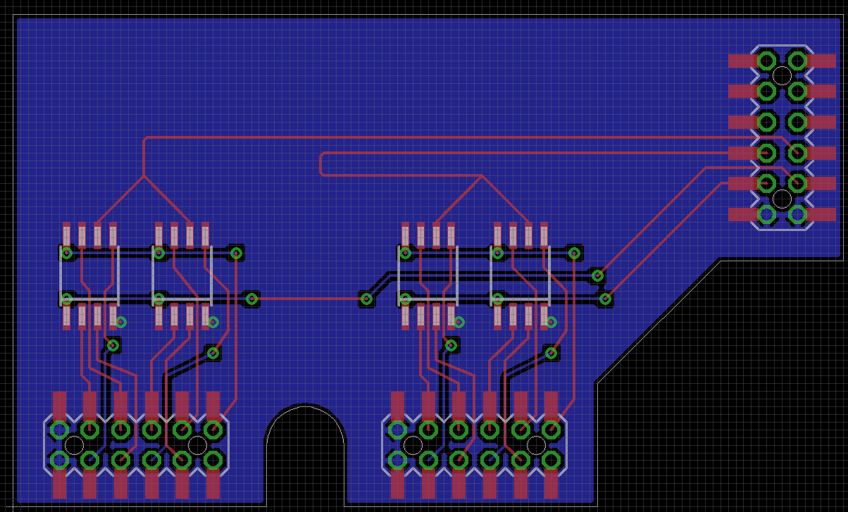
Here's a start at what I'm thinking for PSRAM on P2-EVAL. It would sit inside the P2-EVAL. It's obviously not done and still needs work on things like:
-bypass caps
-pullups on CE pins
-thicker tracks for power
-labels
-bring devices closer to connectors to shorten data lengths more
-etc
Not sure now if it would be safe to add a secondary group of PSRAM chips due to having trace stubs rather than direct point to point wiring, so this PCB is just 4 devices for now. I'm already worried about the vias on one data pin on each chip. Those alignment holes in the middle of the 2x6 SMD connectors are a PITA.
The clock gets snaked in an attempt to try to match the lengths (at least on this board) if a shared 16 bit bank of 4 devices gets the clock driven by two P2 GPIO pins.
Here's the rough idea for the double sided load. The other 4 parts are flipped on the other side, so the signals can mostly go through vias and match up reasonably well. I just don't know how the data bus signals would work at high speed or if we'd get all sorts of nasty reflections etc. Data is clocked at up to 160MHz or so.
@rogloh said:
In the last week or so I've ported my HyperRAM driver over to support PSRAMs, in the likely eventuality the new P2-Edge will be fitted with that memory.
PSRAM is now working with my video driver and I did a graphics benchmark comparison between HyperRAM and PSRAM and recorded a couple of videos showing the operations being performed. They are available in the attached zip files.
The PSRAM memory is clocked at 148.5MHz but is 16 bits wide, it's data sheet spec is 144MHz max clock but I can achieve a fair bit higher than this - this 1080p60 test runs only slightly overclocked but I've had it up to 162.5MHz (325MHz/2) in other modes at room temp.
I've just noticed an upcoming HyperRAM family with a 16b bus, from Winbond. I've not found a pin-out for the x16 22 signal pads yet ?
_HyperRAM Key Features
256Mb HyperRAM operation frequency: 200MHz/250MHz
256Mb 30 ball WLCSP: 13 signal pads for x8 and 22 signal pads for x16
Available in a variety of form factors of AIoT end product, including 24BGA, WLCSP, and KGD
Sizes available from 32Mb to 256Mb_
With 9 extra signals for the x16 version, it's potentially 8 more data bits + another RWDS signal vs the x8. I wonder if it's just two dies in the same package, sharing CS and CLK pins and giving twice the bandwidth.
So on a P2 it might be 20 pins for 16 bit HyperRAM bus vs 18 pins for a 16 bit PSRAM bus to gain a 2x speedup over PSRAM using DDR.
It could be a challenge to compute and control two separate RWDS pin states in a timely way during the write transfer for full byte masking on start and end addresses. I already control one RWDS and it takes up most of the idle instruction cycles available during the address phase IIRC. You might have to start/stop the streamer in the middle of the write transfers for this or drop down to sysclk/4 during the address phase (which would increase latency).
@rogloh said:
With 9 extra signals for the x16 version, it's potentially 8 more data bits + another RWDS signal vs the x8. I wonder if it's just two dies in the same package, sharing CS and CLK pins and giving twice the bandwidth.
So on a P2 it might be 20 pins for 16 bit HyperRAM bus vs 18 pins for a 16 bit PSRAM bus to gain a 2x speedup over PSRAM using DDR.
It could be a challenge to compute and control two separate RWDS pin states in a timely way during the write transfer for full byte masking on start and end addresses. I already control one RWDS and it takes up most of the idle instruction cycles available during the address phase IIRC.
The lazy approach would be to use 2 die, and drop a couple of power pins.
Maybe a simple OR gate can merge 2 RWDS ? as it's only during the address phase you need to know if either part needs a refresh delay adder ?


Comments
Looking at it, probably the hblanking is too small for VGA signalling.
Where the sync lands within the blanking will affect the picture position on display. I prefer to make the frontporch minimal. I've see-sawed between having a wide hsync and not. I'm tending back to small for both and leaving a large backporch. Same for vblanking timings. This usually works best for adjustment ranges in the OSD.
EDIT: CVT hasn't proved all that useful for me in the end. I've tried it many times but I always end deviating off.
PS: An old rule of thumb I had for VGA was add 20% to the horizontal resolution to give you the minimum htotal.
Yeah I know it isn't something that certainly wouldn't work with CRT VGA monitors, I was hoping in vain that it might work with monitors that accept VGA but scale to an LCD panel. I know my Dell monitor accepts a reduced blanking 1920x1200 mode over VGA for example @ around 7.7% blanking to total horizontal time.
There still might be something that sits between the 325MHz and 268MHz P2 speed that would work with UXGA and let it run with HyperRAM too. It'll be non-standard though.
It would be a lot easier to drop the 2:1 sysclock to pixel ratio. Go 1:1. That would allow large blanking and good flexibility on sysclock. Extend/trim the backporches to suit whatever sysclock frequency you want.
I could do that but the HyperRAM bandwidth halves as well. At least we could get a picture.
I've been experimenting for a bit with UXGA around 300MHz (150MHz dot clock) but just can't get things to sync. Monitor always says "cannot display this mode" etc.
I guess we can still get a 4bpp mode at UXGA but lose the 8bpp one. This 16 bit PSRAM board is nice in that it runs at P2 clock speeds that prevent the reliable HyperRAM transfer (v1 anyway). I've pushed it to over 350MHz (175MHz RAM) and it was still going. So if the P2 Edge gets PSRAM, it won't be an issue.
Update: Ok, I tried it at 170MHz, LCD monitor gets a picture but it's offset a bit. Could probably work with that.
I found an EDID dumper and found some limits to my monitor. Looks like it can't go over 170MHz dotclocks.
./edid-decode < edid.txt Extracted contents: header: 00 ff ff ff ff ff ff 00 serial number: 10 ac 10 a0 53 4d 31 31 1c 0f version: 01 03 basic params: 80 34 21 78 ee chroma info: ee 50 a3 54 4c 9b 26 0f 50 54 established: a5 4b 00 standard: 81 80 a9 40 71 4f b3 00 01 01 01 01 01 01 01 01 descriptor 1: 28 3c 80 a0 70 b0 23 40 30 20 36 00 07 44 21 00 00 1a descriptor 2: 00 00 00 ff 00 50 36 35 34 30 35 37 34 31 31 4d 53 20 descriptor 3: 00 00 00 fc 00 44 45 4c 4c 20 32 34 30 35 46 50 57 0a descriptor 4: 00 00 00 fd 00 38 4c 1e 51 11 00 0a 20 20 20 20 20 20 extensions: 00 checksum: 27 EDID version: 1.3 Manufacturer: DEL Model a010 Serial Number 825314643 Digital display Maximum image size: 52 cm x 33 cm Gamma: 2.20 DPMS levels: Standby Suspend Off RGB color display Default (sRGB) color space is primary color space First detailed timing is preferred timing Display x,y Chromaticity: Red: 0.6396, 0.3300 Green: 0.2998, 0.6074 Blue: 0.1494, 0.0595 White: 0.3125, 0.3281 Established timings supported: 720x400@70Hz 9:5 HorFreq: 31469 Hz Clock: 28.320 MHz 640x480@60Hz 4:3 HorFreq: 31469 Hz Clock: 25.175 MHz 640x480@75Hz 4:3 HorFreq: 37500 Hz Clock: 31.500 MHz 800x600@60Hz 4:3 HorFreq: 37900 Hz Clock: 40.000 MHz 800x600@75Hz 4:3 HorFreq: 46900 Hz Clock: 49.500 MHz 1024x768@60Hz 4:3 HorFreq: 48400 Hz Clock: 65.000 MHz 1024x768@75Hz 4:3 HorFreq: 60000 Hz Clock: 78.750 MHz 1280x1024@75Hz 5:4 HorFreq: 80000 Hz Clock: 135.000 MHz Standard timings supported: 1280x1024@60Hz 5:4 HorFreq: 64000 Hz Clock: 108.000 MHz 1600x1200@60Hz 4:3 HorFreq: 75000 Hz Clock: 162.000 MHz 1152x864@75Hz 4:3 HorFreq: 67500 Hz Clock: 108.000 MHz 1680x1050@60Hz 16:10 HorFreq: 64700 Hz Clock: 119.000 MHz Detailed mode: Clock 154.000 MHz, 519 mm x 324 mm 1920 1968 2000 2080 hborder 0 1200 1203 1209 1235 vborder 0 +hsync -vsync VertFreq: 59 Hz, HorFreq: 74038 Hz Serial number: P654057411MS Monitor name: DELL 2405FPW Monitor ranges (GTF): 56-76Hz V, 30-81kHz H, max dotclock 170MHz Checksum: 0x27 (valid) EDID block does NOT conform to EDID 1.3! sRGB is signaled, but the chromaticities do not match EDID block does not conform at all! Bad year of manufactureWhat is most desirable sysclock frequency?
Man, all these constants I need to find and expose/makeup to use your driver ain't much fun. How easy is it to supply a custom screen mode via p2textdrv.spin2? I'm using the demo helloworld.spin2 to test with.
EDIT: I see initVgaCustom(). I guess I can just use that in place of initVga().
Right got helloworld.spin2 compiling now with this
vid.initVgaCustom( -1, VGA_BASE_PIN, VGA_BASE_PIN+4, vid.FLASH_TEXT, 288_000_000, 2, 0, 16, 64, 240, 1600/8, 0, 1, 2, 47, 1200 )... And picture is displayed good.
Hmm, that is the text driver stuff which was intended to simplify things by removing complexity, LOL. I am putting together a demo that is going to hopefully make it easier to use with any luck. The custom screen mode stuff is slightly messy right now. I was thinking of combining the constants for stock resolutions with a pointer for custom timing in the same parameter. Eg, if the value is > 2^20 it is a constant, but if <2^20 it points to a timing structure in HUB RAM.
One annoying thing about SPIN2 is that if you want to wrap some complex functionality with a simpler API, but need to use something from the lower included object, you almost have to duplicate that API in the wrapper object and that adds overheads. It's okay for rarely used APIs but if it's something that is meant to be higher performance it becomes painful. Soon enough your wrapper layer becomes almost as complex as the one underneath.
Good work. Wasn't that hard now was it.
Just tried those settings as well, my monitor still didn't like it. I think it is a crapshoot as to whether it would work or not.
Here try out this binary if you'd like... for some HyperRAM gfx fun - your UXGA mode is in there too.
VGA on P0-7, HyperRAM on P16-31 (some current debug output sent @115kbps):
Really? That was an easy one I thought. Try this:
vid.initVgaCustom( -1, VGA_BASE_PIN, VGA_BASE_PIN+4, vid.FLASH_TEXT, 320_000_000, 2, 0, 120, 152, 264, 1600/8, 0, 1, 2, 45, 1200 )Ah, the 1600x1200 mode doesn't work for me either. Your parameters must be different to what I posted.
Weird, this is what I used from your numbers...and is what is in the demo for UXGA.
UPDATE: Oops, I see the problem, divisor is still 1. Let me update this post with the new values.
uxga_timing ' 1600x1200@60Hz at 162*2 MHz
            long   0 'CLK325MHz
            long   288000000
                   '_HSyncPolarity___FrontPorch__SyncWidth___BackPorch__Columns
                   '     1 bit         7 bits      8 bits      8 bits    8 bits
            long   (0<<31) | (16<<24) | (64<<16) | (240<<8 ) |(1600/8)
                   '_VSyncPolarity___FrontPorch__SyncWidth___BackPorch__Visible
                   '     1 bit         8 bits      3 bits      9 bits   11 bits

            long   (0<<31) | ( 1<<23) | (  2<<20) | (47<<11) | 1200
            long   1 << 8
                   '_Breezeway__C-Burst__FrontPorchHi__SyncWidthHi__BackPorchHi
                   '  8 bits     8 bits     8 bits        4 bits        4 bits
            long   (0 << 0)  ' Back porch MSBs
            long   0   ' reserved for CFRQ parameter
COOL, it worked for me now at UXGA 8bpp when I fixed the divisor. Here's the updated binary...
PS: I like the blit speed! Seems snappy as. Could easy do a GUI with that.
That's the plan my man.
Did the final WUXGA (1920x1200) resolution work for you? That is the last one in the sequence but you many not have a 16:10 monitor.
The cool thing is this fully works in with all the region stuff in my video driver, so you could have a region of the screen as a GUI or something feeding data in from external memory bitmaps, or from a sprite driver, as well as some text status for COGs/debug/coding etc, all at once and just add/remove or slide them up/down dynamically as you need them. Plus it works with PAL, NTSC, component and DVI output too. Also different regions can be in different colour depths at the same time. Only the resolution and border colour is common, though it can be changed on the fly as well (with care).
Yep. Some random data at the bottom of the scrolling blit but everything else looked good. I'm using the old DVI monitor, which is 1920x1200. But it is set 4:3 aspect at the moment so the widescreen modes looks squashed.
Cool, yeah ignore random data at the bottom in the frame buffer. This is just a quickly hacked up simple API feature test/demo and it's not really polished in any way. I just wanted something that could cycle through the modes and draw things in different colour depths etc. I might add bigger font support at some point as the 8x16 text can look quite small on a hi-res monitor. In graphics modes you could do fonts in any size really.
Okay, so the key to VGA signalling is to use the sync frequencies for mode signalling to the monitor. For 1600x1200@60 the needed hsync is 75 kHz. You can then add lots of extra hblank to accommodate higher clock frequencies if desired. And, obviously, remove blanking if wanting to down clock. But must retain the hsync frequency.
Knowing what the right frequencies are, mostly involve scraping the web for sites that tell you. Wikipedia has zip on the matter, sadly.
Oh, and I did find it an advantage to move the hsync position closer to the centre of the blanking too. The CVT spec is good for VGA it seems. Funny that.
Is there any PSRAM accessory board project? I ordered several 64 Mbits PSRAM chips to experiment with.
Not from me (at this stage). Parallax are still testing it all out AFAIK. The board pictured earlier with the flying leads is not ideal on P2-EVAL or the JonnyMac board due to needing more than 16 pins available on the IO header and requiring you to jumper the CLK and CE signals from two other P2 header pins. The CE signal on a flying lead is no big deal but the clock signal length is critical and I found in testing you have to make it really short to work correctly at high video pixel clocks. Move it around and thing can fail because its carrying a clock about 150MHz or so and is quite sensitive.
I think an L shaped PCB board that goes on the inside of the P2-EVAL board outline with a direct clock connection through the board to a third 2x6 pin header with a fixed length would make sense. You could then have multiple CS and CLK pins too, up to 4 of each, and probably up to 8 device footprints on top and bottom PCB surfaces (4 per side). So say 2-4 banks of 8 bits wide memory could be populated but they would operate in parallel at data bus widths of 16 or 8 bits depending on the software. This would be the most flexible way to build it and make the most of the 3 breakout headers attached (24 IO pins consumed).
Now that I've just done a SRAM breakout board and am in the state of mind of making PCBs again, maybe I'll layout a PSRAM one...
Here's a start at what I'm thinking for PSRAM on P2-EVAL. It would sit inside the P2-EVAL. It's obviously not done and still needs work on things like:
-bypass caps
-pullups on CE pins
-thicker tracks for power
-labels
-bring devices closer to connectors to shorten data lengths more
-etc
Not sure now if it would be safe to add a secondary group of PSRAM chips due to having trace stubs rather than direct point to point wiring, so this PCB is just 4 devices for now. I'm already worried about the vias on one data pin on each chip. Those alignment holes in the middle of the 2x6 SMD connectors are a PITA.
The clock gets snaked in an attempt to try to match the lengths (at least on this board) if a shared 16 bit bank of 4 devices gets the clock driven by two P2 GPIO pins.
Here's the rough idea for the double sided load. The other 4 parts are flipped on the other side, so the signals can mostly go through vias and match up reasonably well. I just don't know how the data bus signals would work at high speed or if we'd get all sorts of nasty reflections etc. Data is clocked at up to 160MHz or so.
I've just noticed an upcoming HyperRAM family with a 16b bus, from Winbond. I've not found a pin-out for the x16 22 signal pads yet ?
_HyperRAM Key Features
256Mb HyperRAM operation frequency: 200MHz/250MHz
256Mb 30 ball WLCSP: 13 signal pads for x8 and 22 signal pads for x16
Available in a variety of form factors of AIoT end product, including 24BGA, WLCSP, and KGD
Sizes available from 32Mb to 256Mb_
Sounds interesting jmg.
With 9 extra signals for the x16 version, it's potentially 8 more data bits + another RWDS signal vs the x8. I wonder if it's just two dies in the same package, sharing CS and CLK pins and giving twice the bandwidth.
So on a P2 it might be 20 pins for 16 bit HyperRAM bus vs 18 pins for a 16 bit PSRAM bus to gain a 2x speedup over PSRAM using DDR.
It could be a challenge to compute and control two separate RWDS pin states in a timely way during the write transfer for full byte masking on start and end addresses. I already control one RWDS and it takes up most of the idle instruction cycles available during the address phase IIRC. You might have to start/stop the streamer in the middle of the write transfers for this or drop down to sysclk/4 during the address phase (which would increase latency).
The lazy approach would be to use 2 die, and drop a couple of power pins.
Maybe a simple OR gate can merge 2 RWDS ? as it's only during the address phase you need to know if either part needs a refresh delay adder ?