

PSRAM vs HyperRAM testing
 rogloh
Posts: 6,390
rogloh
Posts: 6,390
In the last week or so I've ported my HyperRAM driver over to support PSRAMs, in the likely eventuality the new P2-Edge will be fitted with that memory.
PSRAM is now working with my video driver and I did a graphics benchmark comparison between HyperRAM and PSRAM and recorded a couple of videos showing the operations being performed. They are available in the attached zip files.
The PSRAM memory is clocked at 148.5MHz but is 16 bits wide, it's data sheet spec is 144MHz max clock but I can achieve a fair bit higher than this - this 1080p60 test runs only slightly overclocked but I've had it up to 162.5MHz (325MHz/2) in other modes at room temp.
The HyperRAM is clocked at this same rate for reads but is using DDR at 8 bits wide so it has the same total read bandwidth. At this P2 clock speed, the reads can (just) transfer at sysclk/1 but writes were using the unmodified breakout board and so still need to operate at sysclk/2.
Turns out the memories are reasonably similar in general use. PSRAM gets an advantage in raw write speed but by having a 32 bit native storage size (4x4 bit byte oriented chips) it needs some additional reads on the headers/trailers of write bursts so all the other untouched bytes inside the 32 bit word do not get corrupted when unaligned byte/word writes occur that don't fill the entire 32 bits. This is its only real disadvantage vs HyperRAM which has its RWDS qualifier signal for this purpose. The best advantage is you get two clock phases to sample since the bit period is twice as wide with PSRAM and this simplifies the read code and makes it more robust over the full frequency range.
You can see from the benchmarks both memories performed roughly in the same ballpark. PSRAM will have better performance for longer aligned write transfers and it improves horizontal fills significantly. For single pixel writes and vertical lines the PSRAM has some more burden due to it's Read-Modify-Write overheads on each pixel, but it's not really that significant as the overall service delay hides some of this. In any 32bpp mode this would disappear too.
PSRAM Test P2@297000000Hz,1920x1080x8 RAM delay=11 run 1
128x128 BitBlt Test Rate=1461/s
512x512 BitBlt Test Rate=206/s
Circle Draw Test Rate=1720/s
Point Draw Test Rate=174662/s
Text Draw Test Rate=622/s
Rectangle Draw Test Rate=9432/s
Box Draw Test Rate=3240/s
Horiz Line Draw Test Rate=112357/s
Vert Line Draw Test Rate=3447/s
Triangle Draw Test Rate=3148/s
HyperRAM Test P2@297000000Hz,1920x1080x8 RAM delay=13 run 1
128x128 BitBlt Test Rate=1543/s
512x512 BitBlt Test Rate=176/s
Circle Draw Test Rate=1774/s
Point Draw Test Rate=180700/s
Text Draw Test Rate=611/s
Rectangle Draw Test Rate=10692/s
Box Draw Test Rate=3781/s
Horiz Line Draw Test Rate=89113/s
Vert Line Draw Test Rate=4000/s
Triangle Draw Test Rate=3401/s
Comments
Here was the setup, and the board from VonSzarvas I used for testing.
Cool. Good work.
I've added a line drawing accelerator to my P2 external memory drivers (both PSRAM and HyperRAM). PSRAM looks perfectly crisp the way up to 1920x1200 8bpp which is great. But I noticed that HyperRAM has some sort of issue. Now I'm using it with hi-res lines I'm seeing a lot of errors in the HyperRAM data output that I hadn't really seen before with larger flat shaded objects that used block fills. It appears I might have a bug in the single byte write routine or some other timing issue with the HyperRAM. It doesn't always seem to take the data and I sometimes just read back zeroes after writing to it and pixels are missed and gaps in the lines appear. This happens all the way down at 100MHz so it's not an overclocking thing. I'll have to dig into the timing more there now.
Once started, this line drawing code computes and writes pixels on a given line into the external memory, and will yield back to the poller after each memory write unless you lock the transfer in which case it doesn't yield (but you could corrupt video this way). If high priority COGs like the video driver are not yet requesting any memory transfer a new pixel can be written. This way it doesn't interfere with the video output. If you had two memories and ping ponged without yielding you could draw lines even faster. Be good to try that out sometime with two PSRAM boards and see just how fast it can run.
This image was from the PSRAM output at 1920x1200 8bpp. I'll need to fix the HyperRAM output once I figure it out.
Here's the code that does the line drawing I've put into hyperdrv.spin2 and my new PSRAM driver. It was actually quite small in the end, only 24 longs. It runs as straight line code in HUB exec mode, making use of a graphics expansion capability I already planned in the driver for this purpose a while ago. You just need to spawn the bus with the F_EXPANSION flag to enable it as it is still experimental. I'll try to send a full demo out soon.
        orgh

gfxexpansion
                            'simple line drawing graphics expansion of memory driver

                            cmp     addr1, addr2 wz         'see if we've reached the end
            if_z            jmp     #donerepeats            'nothing more to draw
                            add     total, #1               'restore total after decrement
                            mov     b, offset1              'get error term
                            shl     b, #1                   'compute e2 = 2 x error
                            getword d, offset2, #0          'get dx = abs(x0-x1)
                            sar     offset2, #16            'get dy = -abs(y0-y1)
                            cmps    b, offset2 wc           'compare if e2 >= dy
                            mov     c, #0                   'clear accumulator reg
            if_c            skip    #%1110                  'if not, skip
                            decod   a                       'decode as 1,2,or 4 byte size
                            add     offset1, offset2        'err+=dy
                            testb   total, #16 wz           'check sign sx
                            sumz    c, a                    'accumulator +/- size a (x0+=sx)
                            cmps    d, b wc                 'compare if e2 <= dx
            if_c            skip    #%11110                 'if not, skip
                            rolword offset2, d, #0          'restore offset
                            add     offset1, d              'err+=dx
                            testb   total, #17 wz           'check sign sy
                            getword d, total, #0            'get line width
                            sumz    c, d                    'accumulator +/- linewidth (y0+=sy)
                            encod   a wc                    'restore size and set carry
                            mov     count, #1               'reset the fill width
                            jmp     #readmask               'continue filling
This SPIN2 API below can be added to memory.spin2 for drawing a line. It's not 100% robust against out of bounds conditions at this point (it's more of a testing API) but it works. You need to provide the start address of the pixel at one end of the line (dstAddr) and an x-offset and y-offset distance to the other end of the line. Offsets can be positive or negative. Lines can be drawn in any direction. The pattern parameter is the colour for your bit depth selected by data size. It's limited to 8,16,32 bpp modes with single pixel widths, so it's hardly universal, but it will come in handy.
PUB gfxLine(dstAddr, dstPitch, xoffset, yoffset, pattern, listPtr, datasize) : r | req, m, list, dx, dy if datasize == 1 req := R_WRITEBYTE elseif datasize == 2 req := R_WRITEWORD elseif datasize == 4 req := R_WRITELONG else return ERR_INVALID ' when no ptr, fill in scratch space and execute a single request list if listPtr == 0 m := addrMap[dstAddr>>28] if m +> LAST_INSTANCE return ERR_UNMAPPED if long[getMailboxAddr(m+1, cogid())] < 0 return ERR_MAILBOX_BUSY ' don't clobber existing list item list := @listdata[(m*NUMCOGS + cogid())*ITEMSIZE] else ' construct list item only, don't execute list := listPtr dx := abs(xoffset) dy := -abs(yoffset) long[list][0]:= req + (dstAddr & $fffffff) ' starting pixel address long[list][1]:= pattern ' colour long[list][2]:= 1 ' count is 1 pixel long[list][3]:= req + ((dstAddr & $fffffff) + (xoffset<<(datasize>>1)) + yoffset*dstPitch) ' final pixel address long[list][4]:= $80000000 | ((xoffset < 0) ? $10000:0) | ((yoffset < 0) ? $20000 : 0) | dstPitch ' signs and pitch long[list][5]:= dx + dy ' initial error term long[list][6]:= (dy << 16) | dx 'line width and negative height long[list][7]:= 0 ' no link pointer to next item if listPtr return listPtr + 28 ' return the address of link pointer to allow chaining etc r := execList(m+1, list, 0)That is fantastic, Roger! 1080p at 8bpp, wow!
I note the PSRAMs with DDR do have a RWDS like signal, labelled DQSM.
Evan, do you have a part number?
They basically look the same as a hyperRAM, have the same pinout I think, but the CA phase is a little different - IS66WVO8M8DALL/BLL is an example. Scroll down to the OctalRAMs - https://www.issi.com/US/product-serial-sram-and-serial-ram.shtml
There is SOIC-16 pin packages too but they're limited to 4-bit data width only, even though there is four unused pins on the package.
Yeah it looks pretty nice in person and can make a nice hi-res GUI. For standard frame rates I think the truecolour mode will be limited to about 1280x720p as it then will consume most of the memory bandwidth and require a very fast P2 ~ 350MHz. Though I have pushed to 1280x800 with reduced blanking in another experiment I did, but my LCD monitor didn't like it much and recognized it at XGA instead and rescaled it. Interlacing it or dropping to 720p24 would help further and might get it out DVI instead of VGA perhaps. Will have to see just how far it goes...
Yeah, VGA signalling screen mode detection is iffy, the monitors/TVs each have a preset list and there's no stepping outside them. DVI signalling seems to be bulletproof on resolution detection. I'm thinking modes are no longer a thing, although they will be named when a resolution matches.
I'm guessing there is blanking info in the special bit patterns that allow precise horizontal and vertical resolution detection.
I'd be happy with a 16-bit 960 x 540 display. Which I've done over DVI already.
Here we go, at 300 MHz even. That's a comfortable sysclock I think. Okay, that was broken.
Working one is 320 MHz ... It has very small blanking, let me know if okay with you.
EDIT: Updated with 123 ohm BITDAC pin drive.
The thing I found with these external RAMs is that because they're locked to the CPU speed for their transfers, some resolutions have enough bandwidth to work out, some don't, and it's a binary yes/no thing that directly relates to their P2 clock to pixel clock ratio. A ratio of 5 or more will be able to do truecolour, a ratio of 3 or more will be able to do 16bpp, and a ratio of 2 or more will be able to do 8bpp. This assumes for HyperRAM it is doing sysclk/1 reads, and for PSRAM it is 16 bits wide.
If you can find a P2 clock speed that achieves 960x540 video output, as long as the P2 core : pixel ratio (ie. pixel divisor) is 3 or more you'll be able to do 16bpp colour.
Without the mouse enabled, in some cases you "might" be able to subtract one from these divider values and rely on the blanking time to pay for the jitter and extra overheads in accessing the memory but it is not certain and you'll barely have any write bandwidth left over. The numbers above are safer to rely on.
Truecolour gets more costly in terms of both bandwidth and storage because it needs to transfer 32 bits for each pixel instead of the raw 24 bits it really needs. 8 bits are wasted in the memory transfer etc, but it also makes pixels long addressable which is very helpful.
DVI is fixed at 10:1 ratio. You know that! :P
A downer with the tweaked Spiral Demo I posted above is it is only 55 Hz scan rate. Which isn't the end of the world, but to get 60 Hz scan rate requires sysclock at 347 MHz or more.
50 Hz scan can be done with 290 MHz. This is likely what my broken example was attempting at 300 MHz.
Yes I might have missed that you were doing it over DVI, though you did actually state that in the edited post. Above I was talking in general terms, ie. including VGA. By the way there are fractional dividers supported in the driver as well for VGA, though I tend to avoid using them at small ratios as you might get pixels that are 50% wider than others, for example if you picked 2.2 as the ratio some pixels would be 3 clocks wide and others 2 clocks wide. For feeding an input device that later smooths things, like a TV, it might not matter or be less noticeable.
I just tried out your modified Spiral demo and it displayed okay on my Dell 2405FPW and reported 960x540@55Hz.
Good. I've worked out that minimum DVI blanking, for the lower end resolutions at least, is 96 dots horizontal and 8 lines vertical.
I brought up the DVI discussion due to the old annoying mode detection issue on VGA. And many people are expecting HDMI (DVI) output now as well.
And the enforced 10:1 ratio leaves a good amount of bandwidth for some action on screen.")
What was the BitDAC mode you used for DVI signalling? I see the spiral demo currently has 1k ohm or 1 mA.
Thanks, I've updated the attachment above.
Oops, I'd left in the 50 Hz vertical scan rate setting. No biggie, just set a higher sysclock for faster scanning.
Notably that produces a horizontal scan rate of just 27.4 kHz. That's a frequency out of bounds and not supported by monitors on VGA signalling. I guess DVI threw that arbitrary limit away too. Nice to see.
[deleted] Too wild a guessing on my part.
That latest demo required 300MHz operation for me (52Hz refresh reported). Trying 290MHz was just too low for my monitor to sync to it. Maybe something in between could work.
Update: I found that 296MHz was the lowest P2 clock it could sync to with 1MHz steps tested. Reported 51Hz then on the monitor.
Oh, that'll be the hsync too low. So some monitors are still fussy even on DVI then. Pity.
Calculating 296 MHz back, comes to bang on 28 kHz hsync.
okay, I've reinstated ASMCLK now. Here's 350 MHz example with 60 Hz vsync and 33 kHz hsync. I've been running this for most part of an hour now. Prop2 is staying luke warm. But is really only one Cog working hard.
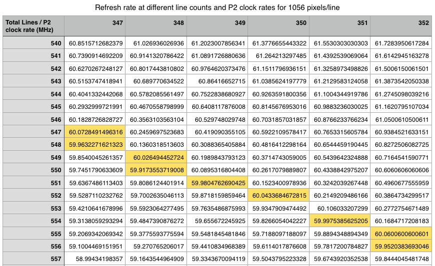
Here's a table for number of lines to hit 50Hz operation as close as possible as you vary the P2 clock and the total line count (assuming 1056 pixels per line).
and another for 60Hz...
The minimum Hsync is the one that catches you out. Adding more vblank lines isn't very useful until you're exceeding 75 vsync.
That's another feature of going DVI over VGA. Reduced blanking is better supported.
Yes it can catch you out, and this table is really only for DVI displays that can accept such a low hsync rate. VGA would probably not like it.
I suppose, if you're trying to maximise frame times for the software, targetting 50 Hz has an advantage.
I'm a little wary of this approach though, because I'm confident most LCDs are locked at 60 Hz scan rate. Once the transmission deviates more than a hertz or two from 60 Hz the panel will default to it's own clock and the built in scan converter will take over the job of sync'ing as well as the pixel scaling it's already performing.
EDIT: It is possible that LCD panels can take a wider band clock though. It might need smarter drive biasing and likes. :shrug:
EDIT2: Actually, what they might have been doing for a while now is same as the variable-refresh-rate (VRR) tech. Where the raw LCD panel is configured for very fast scan rate. I think the scan converter bursts the data into the panel at this rate always. But then has automatic variable number of blanking lines where it can pace out to a slower externally supplied scan rate. This way, without any compute complexity, they can stay in scan sync without any loss or distortion.
VRR takes this one step further and exposes the variable blanking to the video source.
Yeah I was thinking more for panels in TVs that probably like to be fed with either 50/60Hz. Hopefully if they accept the rather low hsync rate over DVI/HDMI, they'll at least be happy with this vsync rate.
Standard TVs are probably far fussier while those cheaper no-name brands seem to accept a lot of different input rates.
I have 1024x576 HDMI timings @ 50 Hz, signaling 624 lines @ 354 MHz CPU clock at exactly the same frame rate as 8-bit Atari") and maybe Amiga which have the same clock basics. The P2 RAM allows only 4 bpp graphics in this mode, so the external RAM is needed even for 8 bpp. The pixel ratio is of course 10:1
and maybe Amiga which have the same clock basics. The P2 RAM allows only 4 bpp graphics in this mode, so the external RAM is needed even for 8 bpp. The pixel ratio is of course 10:1
These PSRAM chips at least aren't BGA