

Flyback diodes question
 T Chap
Posts: 4,260
T Chap
Posts: 4,260
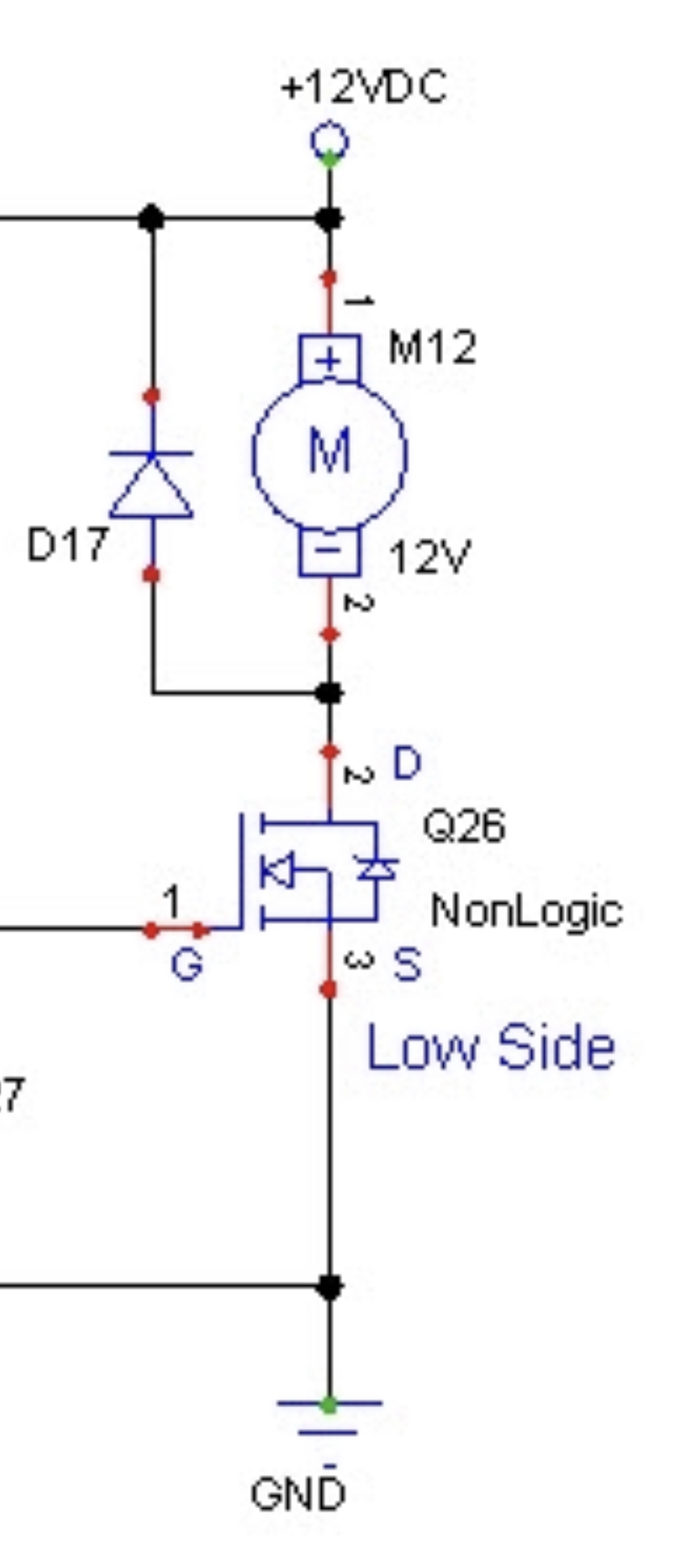
I’m just curious where the energy goes when you cut the low side. I always imagined that you wanted to take the energy from a collapsing coil on a relay or motor to GND. But if GND is removed what is happening. Does the spike dissipate back in the coil ?
I’ve seen the same design with relays cutting the low side. Some mosfets may allow their internal diode to pass the spike to GND even if the gate is 0? But in the case of turning on a motor on the low side with a relay only the question is still relevant. The fly back diode across the coil has no oath to GND. Only +V
Comments
It has little to due with GND, this is not lightning . The coil becomes a power source that is the opposite of the voltage applied to the motor. So Think of motor as a battery and the power flowing backwards out of it is then applied to the diode which looks like a short.
Mike
T Chap,
Where the kick-back or shunt diode is placed depends on its function.
Normally they are placed across transistors to protect them because transistors can not take a lot of reverse voltage.
These diodes are placed across a fast-switching inductive load to suppress the voltage spikes which the rest of the circuit would see as noise.
There might also be noise suppression capacitors on the motor leads.
The short answer is that yes, the energy dissipates in the resistance of the coil, and a bit in the diode.
The trouble though with a flyback diode across a relay coil is that even after you have turned the relay off, there is still current flowing through the coil and this keeps the relay energized longer but not stronger. This also had the bad side effect that the contacts don't snap open but can also weld together eventually depending on the circuit. One simple trick is to soft clamp the voltage by using a Zener in series with the diode. My2cents.
The 24vdc relay is switching a 24v reversible motor but a big mosfet first connects or disconnects the low side supply to the relay for the motor before the relay makes or breaks, so the contacts don’t get arc’d as there is no path to GND for the motor during any relay switching. Only after the relay is in the right state for direction does the low side power get connected via mosfet. Also getting a benefit of PWM from using the mosfet to control speed. The Relay is just to form an hbridge for direction. I use a big IRL logic level mosfet on the low side of the relay coil. The dark blue line is the scope on the low side of the relay coil. ON is the relay coil low side connecting to GND ie trace goes LOW. OFF is relay coil turning off trace goes back HIGH. Purple is the P1 > logic level n channel gate And yellow is motor starting to turn. T-ON is delay from relay getting into the right direction and the mosfet turning on the low side to the motor. T-off is the motor decel after turning off the mosfet. This is with 1n4004 on the relay coil. Second image has little spike on low side of relay coil when turning off without 1n4004 attached. Very clean transitions. A second smaller board contains the Dpak2 logic mosfets that provide the motor LOW. Also the +24V power to each motor first passes through .1R>INA138>Op Amp>Comparator with the P1 setting the references via DAC for dynamic current trip setting.
EDIT Updated images. First upload had a scope trace in AC coupling and was confusing.