

P1 BLDC Asm Question (Solved)
 lardom
Posts: 1,659
lardom
Posts: 1,659
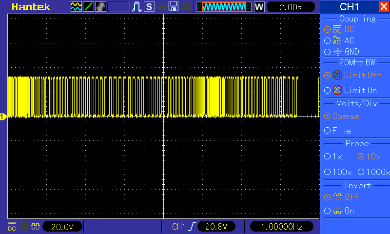
I'm working on a driver for a sensorless brushless motor. The motor will run in closed loop but I don't have a startup sequence yet. I have to spin it with my fingers. The screenshots of pin #8 shows a wider pulse at the higher speed and I don't know why it's happening. The one on the left is running at 75Hz and the pulse width is correct. Every pulse represents step 1 and 2 in a six step sequence. You can see where two equal sized pulses would fit between them.
On the right it's running in closed loop at 1.4Khz and the pulses are wider by half...or three steps wide.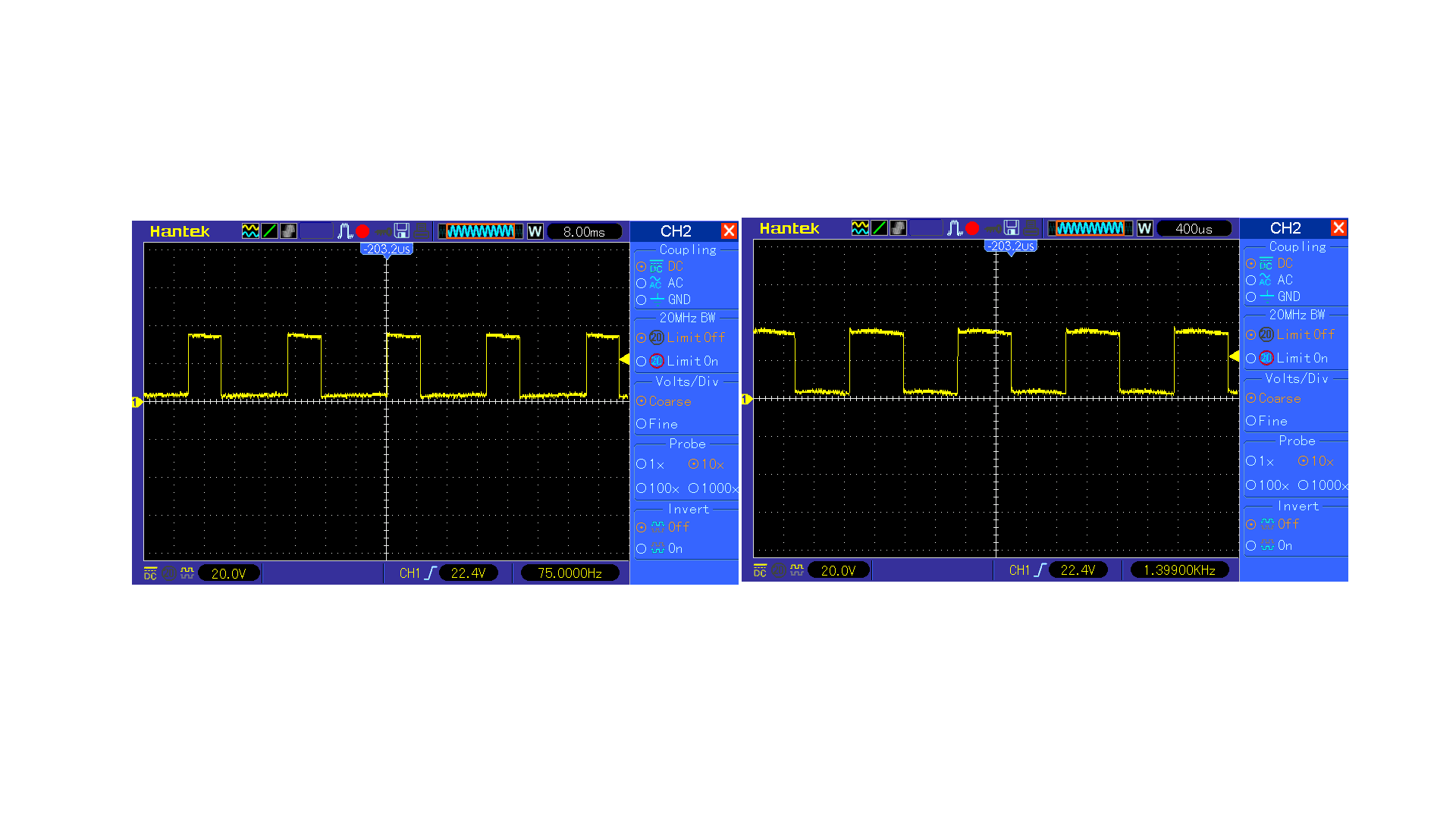
Here is part of the code:
Loop     or       outa,     step_1
         waitpeq  A_phase,  A_phase       'comparators
         andn     outa,     step_1
         or       outa,     step_2
         waitpne  B_phase,   B_phase
         andn     outa,     step_2
         or       outa,     step_3
         waitpeq  C_phase,   C_phase
         andn     outa,     step_3
         or       outa,     step_4
         waitpne A_phase,   A_phase
         andn     outa,     step_4
         or       outa,     step_5
         waitpeq  B_phase,   B_phase
         andn     outa,     step_5
         or       outa,     step_6
         waitpne C_phase,   C_phase
         andn     outa,     step_6
         jmp                #Loop
Comments
Have you tried converting some of Takao's code?
Here is a collection diagrams, and Arduino code, it represents about 1/3 of
the info he has posted.
I hope you will find it useful
Bill M.
Is there another cog handling the pwm?
Edit: I added "Example of a few BLDC programming issues.pdf"
Thank you. I looked at the pdf's. I will definitely refer to them. I don't read C but I will download the Arduino IDE and learn the code.
I'm not using PWM yet. I'm using low voltage and an adjustable power supply. My plan is to use a second cog to count the transitions of one of the comparators every 200ms, sort of like a tachometer, and use that data to adjust a delay between 'zero-cross' and commutation but that could change as I go.
I use this code to count the time that the pin is high and low which could give you speed without counting.
  CTRA = 0x30000000 | s->FeedBack; // get low count
  CTRB = 0x20000000 | s->FeedBack; // get high count
  FRQA = 1;
  FRQB = 1;
  if (1)
  {
    while (get_state(s->FeedBack) == 0);  // wait till high
    PHSA = 0;
    while (PHSA == 0);
    PHSB = 0;
    while (get_state(s->FeedBack) == 0);
    SLow = PHSA;
    while (get_state(s->FeedBack) == 1);
    SHigh = PHSB;
    SLow = SLow/80; // In Microseconds
    SHigh = SHigh/80; // In Microseconds
    STotal = SLow + SHigh;
Mike
Here is the thread that I created the pdf's from. My pdf's are
a few years old, so they don't include 3.3v micros (stm32, Teensy)
that were discussed afterwards.
DIY BLDC Controller
Bill M.
@"Capt. Quirk" thanks for the link. BTW I think I just realized why the closed loop pulse is larger. I think commutation is occurring 30° early. I have a delta wound motor.
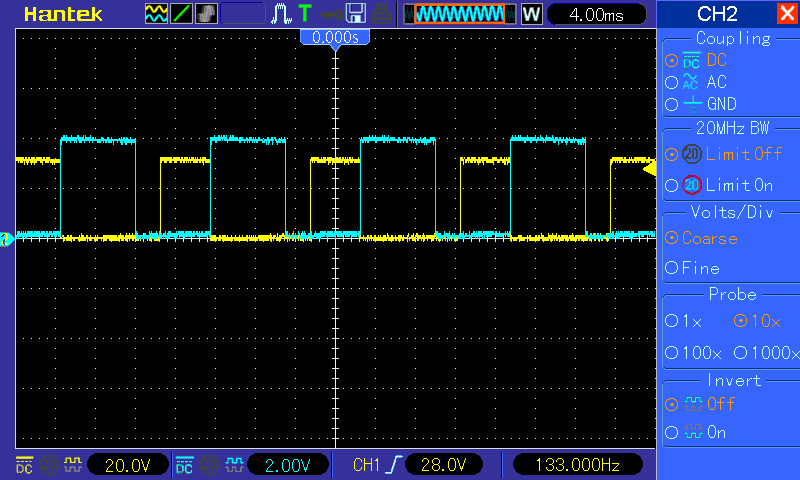
Here's a screenshot of one phase and one comparator running in open loop. The yellow trace is an i/o pin which stays high for 120° wide and the blue trace is a comparator which stays high for 180°. I clearly have to spend a few days studying Takao's material.
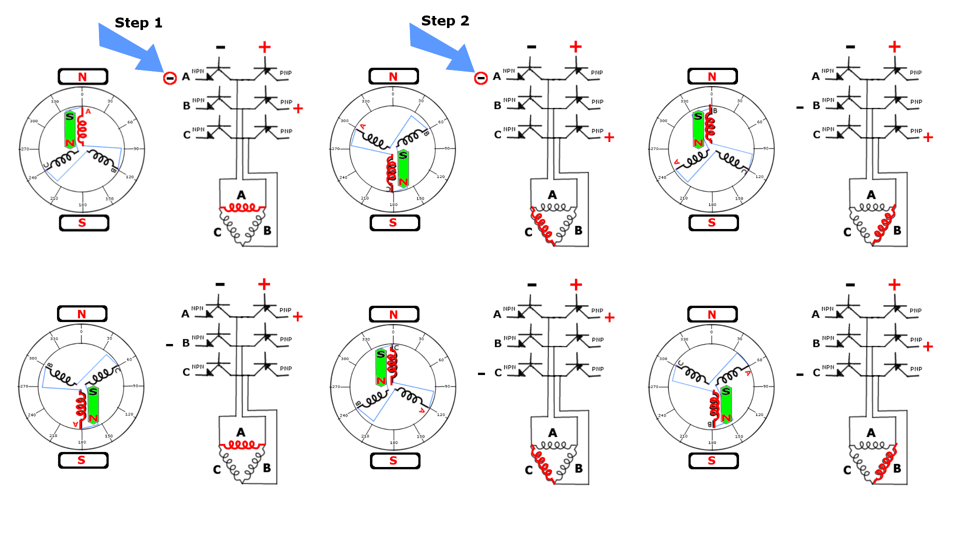
This post for the benefit of anyone who searches this topic in the future. I made this diagram to help me picture what's going on. In a delta wound BLDC only one phase is driven at a time. The coils are connected end to end. In each successive commutation the leading phase aligns with the opposite magnetic pole and rotates the rotor by 60°. I placed an oscilloscope probe on the i/o pin indicated by the arrow. When I place a second probe on another i/o pin I can identify where the second pulse appears in the sequence.
Would you not use an ESC to drive this motor and monitoring of the windings will lead to large kickback voltages which is not good.
Mike
I can see how someone would see this as bad circuit design. I didn't think of that. It is intended as just a diagram. The actual circuit has diodes and fairly high value resistors. I'm supplying 4.5 volts but if I get bad reactions to it I'll delete it or ask @Publison to remove it.
What type of BLDC motor are you working with, and what is your goal?
Bill M.
@"Capt. Quirk"
I have a collection of small delta wound drone motors. My original goal was just to see if I could figure out how to drive it out of curiosity. I'm a hobbyist who loves the challenge of programming the different types of hobby motors. The one motor that still has me stumped is the brushless motor. Not understanding how to get from open loop to closed loop bugs me.
I started the project some years ago and could only manage open loop in Spin so I put the breadboarded circuit aside. I got an oscilloscope this past year and wanted to try again as soon as I got the chance.
If I can succeed with a startup sequence my ultimate goal would then be to build an esc powerful enough for an electric paramotor. Yep, I want to fly an electric paramotor!
That's not a goal yet because I've never built anything that uses power mosfets or igbt's so there's a very long road ahead.
I downloaded the Arduino terminal software but I could not open the "C" documents from Takao. What app opens them?
For Arduino code they label them .INO file which are just .C or CC files.
So to open that file in Arduino you would create a folder named the same as the INO file name, "TAKAO" and place the file "TAKAO.C" in it. Then rename the file to "takao.ino". Now the file should open.
My understanding of ESC's is that two polls are active with one not and they use the one that is not powered to sense the voltage of the dead winding as the magnet moves over the coil.
Drone motors are open loop and that they just pulse the motor in a certain order to make them spin. I have had several people complain about motors stalling while they are flying there drones because they use large props and when the change in speed is to fast the motor locks up because it is energizing the wrong winds as the motor is not able to keep up with the speed of the pulses.
Most drone motors have 12 or more polls so I was confused at first about your explanation and drawings.
Mike
You are the man!") When I read that drone motors are open loop I actually smiled. I went to my Spin object and ramped the motor gradually so I wouldn't lose sync. When I thought it was close enough to lock I switched it over and it immediately sped up. HA!
When I read that drone motors are open loop I actually smiled. I went to my Spin object and ramped the motor gradually so I wouldn't lose sync. When I thought it was close enough to lock I switched it over and it immediately sped up. HA! ")
IMO it would be easier to start with CD-Rom motors, than your brushless quadcopter
motors. A good place to begin is to use the cd rom motors with their hall sensors. That
way you will always know the start position. I have provided simple code and schematics
for driving a sensored cd-rom, other sensored brushless motors, and for an r/c car.
Later the cd-rom motors can be converted into capable bldc motors for an airplane
or quad copter. There are tutorials for mounting propellers, adding extended main
shafts with ball bearing support (the shafts are part of a cd-rom assembly), rewinding
the stator, and replacing the magnets. I have supplied 2 links for converting cd-rom
motors.
One hour CD_ROM motor construction
One hour CD ROM motor construction PART2
Winding Scheme Calculator
I have also provided 5 very basic, non sensored bldc motor programs written in
assembly for the 8051. These programs would make a great P2, and maybe P1
projects (maybe, I will use them as a great P2 Pasm project, because the new P2
should be better suited for motor projects, than the P1).
Good Luck
Bill M.
@lardom, you should rename your post to "P1 BLDC Asm Question (solved)"
@"Capt. Quirk", I have a collection of five quadcopters that are currently collecting dust. I've now become a wannabe paramotor pilot. (I watch far too many paramotor videos.)
That's not the main reason for my interest in brushless motors though. It is the challenge. It has nine wires, requires an oscilloscope and it's hard to find information from non-engineers. I 'had' to make a simplified diagram so I could make sense of phases that are 120° apart causing magnets to rotate that are 180° apart. When engineers say "zero cross" I have to translate it as "the point at which the polarity flips". I love the challenge. It was one of the reasons I finally got a scope.
I'm going to focus on brushless motors for the time being. There's a lot to learn about them. I built my first circuit using transistors. I'm now doing simple experiments with bootstrapping logic level N-channel Mosfets.
That's a better title for search. I changed it. Thanks.
@Lardom, Well If you ever decide to strap a 2-stroke engine on your back, and you
want help building a quiet tuned muffler, or pipe, let me know.
Have you read about the BLDC motors electrical gear reduction? or how many times the
stator rotates (electrically) to achieve 1 (mechanical) revolution of the rotor? For example:
a typical drone motor uses a stator with 12 coils/14 magnets = 7:1 ratio. 7 electrical revolutions
of the stator for every 1 revolution of the rotor. Another way to look at it is 84 : 1, 84 cogging
steps for 1 revolution of the rotor.
Your 9 wire stator may be a 3 layer stator. Count the coils (slots) and the magnetic poles
and use the Winding scheme calculator to find out the cogging steps per revolution.
The electrical gear reduction is # of magnet poles /2.
Another example ia a BLDC washing machine motor with 21 coils and 22 magnets has
231 cogging steps per 1 revolution of the rotor, or an electrical gear reduction of 11:1.
I mentioned the washing machine because your paraglider motor might have a lot of
coils (slots), but not as many magnet poles. More magnet poles, more torque, less magnets
equate to more rpm (possibly because it is easier on the micro controller).
Bill M.
"The electrical gear reduction is # of magnet poles /2."
I'm paying attention to everything you said but that sticks out. You also mentioned CD-ROM drives. I've got a couple. They have hall sensors. I can concentrate on PWM. I normally use an ADC chip to read potentiometers which I then use to control DC motor speed. In this case I want to use a rotary encoder to control the duty cycle.
Unfortunately I'm an apartment dweller. I would avoid the additional expense of renting garage space as an absolute beginner in the sport so for me electric would be the best way to start out. One good thing is that I live less than ten miles from a small airport but I'd have to ask permission to use it.
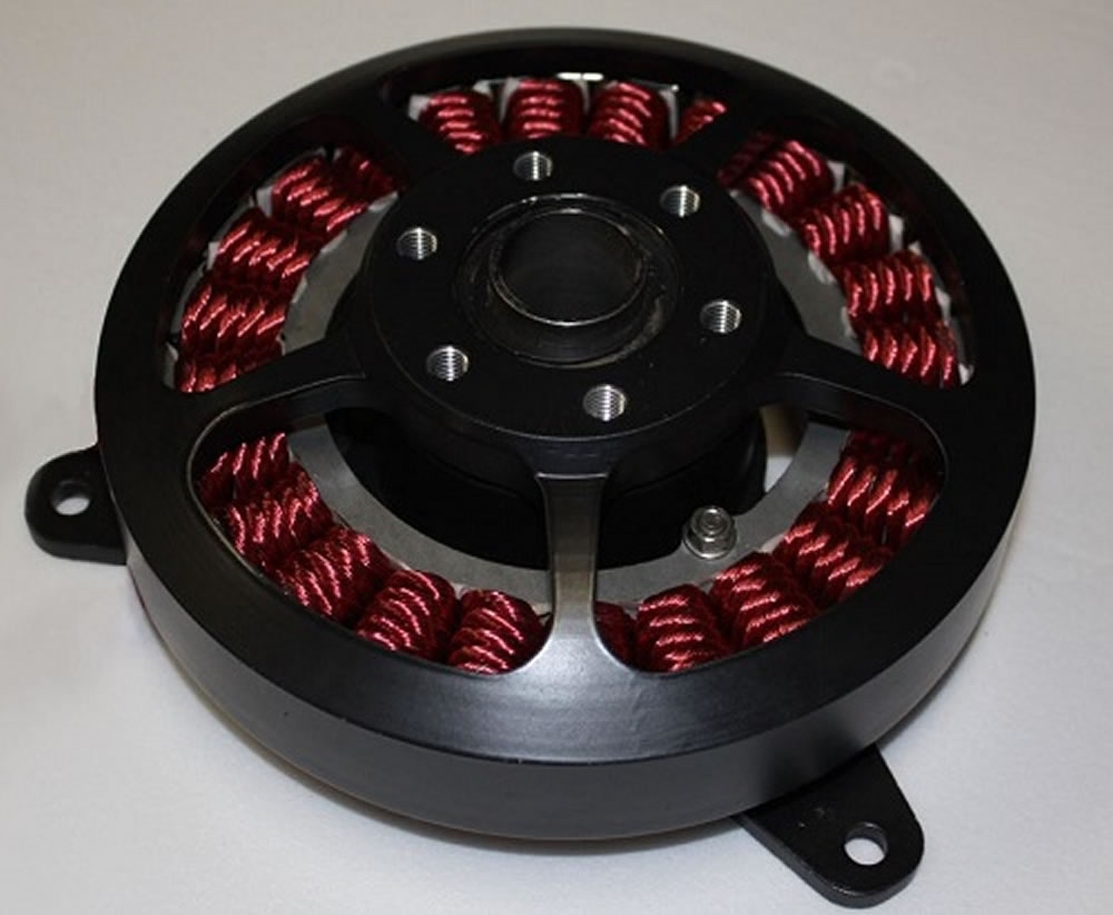
Look at this home built Paraglider motor. Unlike the 2 stroke engines, it
probably is direct drive. It has 24 coils on the stator, and I am guessing
26 magnets on the rotor. That means it has a 13:1 electrical gear reduction,
for every 1 revolution of the rotor, and along the way it will have 312 cogging
steps. Another way to look at it, is to use your 6 step diagram and apply it
to this motor, and repeat it 13 times. The rotor is only rotating about ~27.5
degrees per commutation cycle.
Now look at the next diagram, it is easy to see the 312 cogging steps for 1
revolution of the rotor or propeller.
It might be easier to do this project with the P2.
Bill M.
...
Yes, it would. I stared at the motor for several minutes. It is a thing of beauty. I imagined it as anodized red or blue on a paramotor.
The P2 was made for this. I imagined a 'rescue' drone with a 2-axis camera gimbal and a gripper. I have also thought about an underwater ROV. With a set of pontoons I could lower an enclosed camera under water with a winch maintaining wireless contact. The way I look at it there would be no on-shore tether to get hung up in the weeds or rocks.
BTW, I appreciate the help from you and @iseries. I would still be stuck if you guys did not come to my aid. I have the hardest time trying to understand the assembly section of the Propeller manual. It was written by engineers for engineers. I can't really explain it but you might say something...and the light suddenly goes on in my head. It happens in a way that's different from many people. I have offended some people when I didn't mean to. There are times I want to leave the forum. If I have said anything that sounds offensive or if I say something in the future that comes out of left field I apologize ahead of time.
You are not the only one.
Bill M.
@"Capt. Quirk", Thanks for advising me to change the title of this thread. I have 'just' realized Google has a better search engine than the forum. Thanks a million for your contributions. It has been difficult to track down information on this subject and I'm certain that the information you've supplied will boost this thread in the search algorithm.
I have been working on learning how to modify initialized longs in assembly. (I thought initialized longs were like constants!) Also I'm learning how to get a Pasm cog to monitor pins controlled by a Spin cog. I'm making progress. The screenshot shows an initialized Asm long being continuously modified. This tells me that the Asm cog doesn't require hub access to communicate with the Spin cog in my project and that's a time saver.
I'm trying to figure out how this is possible.
The only way I can see this happening is if the Spin cog is using IO pins to communicate with the PASM cog.
Driving a brushless motor using FETs is on my list of things I want to try. From what I've learned the process seems kind of crazy complicated to do correctly. Texas Instruments have some really interesting YouTube videos on the topic of Field Oriented Control (FOC).
If you ever feel like posting our code, I'm sure there are a couple of us who'd be willing to take a look at it.
I wonder if some of the P2's special math commands like qrotation and qvector would make quick work of the math needed to successfully control a brushless motor.
It is untested theory. I'll explain fully if it succeeds. I know that all cogs can monitor pins controlled by another cog. With posedge detector the Spin cog can see comparator transitions in the Pasm cog. The Spin cog will watch for transition increase, decrease or no change. The Spin 'outa' would then reflect one of those three states through two pins. The Pasm cog will evaluate the input states of those two pins and modify the value in the long associated with the delay between the zero-cross and commutation.
In my mind it would make the energized phase align with the magnetic pole. I could be wrong but it sounds like it could work.
Larry, is the P1 connected to LM339 quad comparator, and does your circuit
include 3 voltage dividers feeding the quad comparator?
What voltage is supplying the bldc motor?
What are you using for an ADC (mcp3204, mcp3208)?
Do you have a schematic of your circuit?
Which starting method are you using, and is there an appnote that you are using as
a reference?
I am not sure if the P1 can actually produce the correct PWM for the motor. I
did post the Ir2101 pwm objects, but I have never used it. As I recall, there was
possible problem with when the clock rolls over. I believe the P1 counters do
not provide a good pwm for driving motors. Other P1 obstacles is the need for
an external comparator and ADC.
On the other hand, the P2 smart pins are capable of doing everything needed
for a generic bldc motor.
Bill M.