

Tachyon 5 - SI5351 dual RF signal source control

I got this code prototype working just this evening, to control the frequency of the two independent channels of an SI5351 chip over the range 4.5kHz to 120MHz.
N.B. fref needs changing to the clock frequency driving your SI5351. My adafruit style board from ebay had a 25MHz crystal. Some others are 27MHz.
To use the code:-
1. the command 0 RFpins! selects the signal out of CLK0 as the active channel, and 1 RFpins! selects the signal from CLK1 as the active channel.
2. the command <frequency> RFtune will then set the frequency of the active channel.
e.g. 1 RFpins! 1000000 RFtune 500 ms 2000000 RFtune would set CLK1 to 1MHz for 1/2s, then change to 2 MHz (no need to reselect the same channel between frequency changes). Frequency setting precision is to within 1-2Hz. Frequency accuracy depends on the crystal used to drive the SI5351 which are never spot-on as marked (mine was 25.008325MHz ). A later version of the code will allow this to be corrected on the fly.
VFOCLKSOFF turns both channels off again. That wants splitting up into per-channel for individual control. (For radio use, they say that best signal purity is achieved when only one channel is used)
There are some test words at the bottom to check the data being created and read the SI5351 settings. During development, the application note AN619 from SI was useful, as was this website. Referring to the SI5351 diagram on this website, my code holds three of the frequency setting parameters constant - e=0, f=1 and c = 1048575, to simplify the maths. The value of c is the largest permitted and this allows b to vary over the widest range and thus give the smallest tuning resolution. The OMD division ratio is maintained as an even integer which is said to minimise clock jitter.
The intention now is to optimise this code for radio tuning application - e.g. only reset the pll when needed (because it briefly interrupts the clock output) and only send changed bytes to the si5351 when a frequency change is made, making for smoother swept tuning. I'll post the result when it's done.
--- SI5351 DRIVER version 1.1 FOR TACHYON 5V7 Bob Edwards Dec 2020

TACHYON V5

IFDEF SI5351
	FORGET SI5351
}
module SI5351 ." SI5351 dual channel RF oscillator driver" ;

--- Record types

--- start a record definition, leave zero offset into the record tos
0	:=	[FIELDS		( 0 -- )

--- define a new field within a record
pre FIELD
	CREATE OVER W, +        ( offset1 datasize -- offset2 )
	DOES> R> W@ +           ( recaddr -- recaddr+offset )
	;

--- finalise a record definition
ALIAS := FIELDS]


--- define a record array type
pre RECORDS ( fielddef recordnumber <arrayname> -- ; arrayindex -- adr )
			GRAB
			CREATE			--- in the dictionary entry...
				org@ W,		--- save start address of data
				OVER W,		--- and save the record size
				* @org W+!  --- then in the dataspace allot reqd no. of bytes
			DOES>
				R@ W@		--- read the start address of the data
				R> 2+ W@	--- read the record size
				ROT * +		--- and compute the start addres of the reqd record
	;

--- constants

$C0      	:= vfoadr				--- SI5351 i2c address
25008325 	:= fref					--- nominal crystal frequency driving the si5351
750000000	:= pllmid				--- PLL frequency midrange
600000000	:= pllmin				--- PLL minimum permitted frequency
900000000	:= pllmax				--- PLL maximum permitted frequency
1048575		:= C					--- this FMD factor is maintained a constant

--- variables
long A
long B

--- Storage definition for one RF channel - remember word and long boundaries - notice order below longs-words-bytes
--- preserve this - the size of the record has to be maintained a multiple of 4, so all records will be aligned
--- This can be achieved by a dummy entry if need be

[FIELDS
	4 FIELD .frequency		--- output frequency
	4 FIELD .Rfreq			--- OMD o/p frequency
	4 FIELD .OMD			--- last OMD
	4 FIELD .pllfreq		--- last Fvco
	4 FIELD .msna_p1		--- FMD intermediate value
	4 FIELD .msna_p2		--- FMD intermediate value
	4 FIELD .msna_p3		--- FMD intermediate value
	4 FIELD .msx_p1			--- OMD intermediate value
	2 FIELD .changed		--- records which registers reg2 - reg12 have changed since last time
	1 FIELD .R				--- R divider
	1 FIELD .reg0			--- SI5351 registers
	1 FIELD .reg1
	1 FIELD .reg2
	1 FIELD .reg3
	1 FIELD .reg4
	1 FIELD .reg5
	1 FIELD .reg6
	1 FIELD .reg7
	1 FIELD .reg8
	1 FIELD .reg9
	1 FIELD .reg10
	1 FIELD .reg11
	1 FIELD .reg12
	1 FIELD .reg13
	1 FIELD .reg14
	1 FIELD .reg15
	1 FIELD .msx_divby4
	1 FIELD .rx_div
	3 FIELD dummy
FIELDS] RFparam


--- Create a 2 record array for the two independent RF sources in SI5351

4 ALIGNORG								--- Ensure array starts on a long boundary
RFparam 2 RECORDS RFparams

--- RFpin! sets which RF channel is current
byte RFsource
pub RFpin! RFsource C! ;					( 0 or 1 -- )
pri RFpin@ RFsource C@ ;					( -- current RF source )
pri RFparams@ RFpin@ RFparams ; 			( -- start adr of reqd params record )

--- Calculation of SI5351 register values

--- from the new output frequency and old OMD setting - the latter is allowed to be any number on start up
--- calculate the new OMD as d + e=0 / f=1 and new pll frequency required

--- calculate R divider and equivalent o/p frequency
pri RCALC	( freq1 -- R freq2 )
	DUP 500000 <
	IF
	  2							--- R = 2 seed value
	  7 FOR
			2DUP * 500000 >		--- check if freq1 * R > 500kHz
			IF
				LEAVE			--- yes, f now > 500kHz,so leave loop
			ELSE
				2*				--- no, then set R = R * 2
			THEN
		NEXT 					--- and try again
		SWAP 2DUP * SWAP DROP
	ELSE
		1 SWAP					--- R is 1 for frequencies over 500000, freq2 is no change
	THEN
;

--- calculate the new Output Multisynth Divider
pri OMD		( freq oldOMD -- newOMD pllfreq )
	2DUP *
	DUP pllmin pllmax WITHIN
	IF					( freq oldOMD pllfreq )
		ROT DROP
	ELSE				( freq oldOMD pllfreq )
		DROP DROP DUP	( freq freq )
		pllmid SWAP /	( freq newOMD )
		DUP 1 AND
		IF
			1+
		THEN			( freq newOMD' )
		SWAP OVER *		( newOMD pllfreq )
	THEN
;


--- calculates a,b for parameters  a + b / c for the Feedback Multisynth Divider from the pll frequency
pri FMD					( pllfreq -- a b )
DUP fref / SWAP			( -- a pllfreq )
C fref */				( -- a c*pllfreq/Fref )
OVER C * - 				( -- a b )
;						( -- a b )

--- The SI5351 requires the above to be packed in the following way...
--- calculate msna_p1
pri msna_p1!
A @ 7 <<		--- A*128
B @ 7 <<
C /				--- 128*B/C
+
512 -
RFparams@ .msna_p1 !
;

--- calculate msna_p2
pri msna_p2!
B @ 7 << DUP				--- 128*B
C /							--- (128*B)/C
C *							--- C*((128*B)/C)
- RFparams@ .msna_p2 !		--- 128*B-C*((128*B)/C)
;

--- calculate msna_p3
pri msna_p3!
C
RFparams@ .msna_p3 !
;

--- calculate msx_p1
pri msx_p1!
RFparams@ >R
R@ .OMD @
128 * 512 -
R> .msx_p1 !
;

--- calculate msx_divby4
pri msx_divby4!
RFparams@ >R
R@ .Rfreq @ 150000000 >
	IF
		$0C
	ELSE
		0
	THEN
R> .msx_divby4 C!
;

--- calculate rx_div
pri rx_div!
RFparams@ >R
R@ .R C@ DUP 1 =
	IF
		DROP 0
	ELSE
	    >| 4 <<
	THEN
R> .rx_div C!
;

--- Now form all byte registers ready to send to si5351
pri reg!
RFparams@ >R
R@ .msna_p1 @
DUP >B R@ .reg4 C!			--- reg4 = LS byte of msna_p1
8 >>
DUP >B R@ .reg3 C!			--- reg3 = middle byte of msna_p1
8 >> 3 AND
R@ .reg2 C!					--- reg2 = MS byte of msna_p1 AND 3
R@ .msna_p2 @
DUP >B R@ .reg7 C!			--- reg7 = LS bytes of msna_p2
8 >>
DUP >B R@ .reg6 C!			--- reg6 = middle byte of msna_p2
8 >> $0F AND				--- MS byte of msna_p2
R@ .msna_p3 @
12 >> $F0 AND
OR R@ .reg5 C!				--- reg5 = Top 4 bits msna_p2 ORed with top 4 bits of msna_p3
R@ .msna_p3 @
DUP 8 >> >B
R@ .reg0 C!					--- reg0 = middle byte of msna_p3
>B R@ .reg1 C!   			--- reg1 = LS byte of msna_p3
1 R@ .reg9 C!				--- reg9 = 1 permanently
R@ .msx_p1 @
DUP >B R@ .reg12 C!			--- reg12 = LS byte of msx_p1
DUP 8 >> >B R@ .reg11 C!	--- reg11 = middle byte of msx_p1
16 >> 3 AND
R@ .rx_div C@ +
R@ .msx_divby4 C@ +
R> .reg10 C!				--- reg10 = MS byte of msx_p1
;

--- calculate and store all division settings in the currently selected channel record
pri PARAM!	( frequency -- )
RFparams@ >R
DUP R@ .frequency !
RCALC SWAP
R@ .R C!
DUP
R@ .Rfreq !
R@ .OMD @
OMD
DUP R@ .pllfreq !
FMD
B !
A !
R> .OMD !
msna_p1!
msna_p2!
msna_p3!
msx_p1!
msx_divby4!
rx_div!
reg!
;

--- SI5351 I2C words - we can use auto register address increment in later versions, but for now...

--- Read byte at register adr in si5351
: VFOC@ ( adr -- byte )
<I2C vfoadr I2C! I2C!				--- select the register at 'addr'
<I2C vfoadr 1+ I2C! nakI2C@ I2C>	--- read the contents
--- SWAP DROP					--- drop the mask value and return the byte
;
--- Write byte to register adr in si5351
pub VFOC! ( byte adr -- )
<I2C vfoadr I2C! I2C! I2C! I2C>
;

--- Wait until si5351 initialisation complete
pri VFOINIT?	( -- )
BEGIN
	0 VFOC@
	$80 AND 0=
UNTIL
;

--- Disable all clock outputs
pri VFO_OPS_DIS	( -- )
$FC 3 VFOC! ;

--- Power down all clocks using register 16-23
pri VFOCLKSOFF	( -- )
	16 FROM 8 FOR
			$80 I VFOC!
	NEXT
;

--- Set crystal as both PLL source
pri VFOXTAL	( -- )
0 15 VFOC!
;

--- Set all disabled outputs low
pri VFOOUTLOW	( -- )
0 24 VFOC!
;

--- Init Multisynths
pri VFOSYNTHINIT	( -- )
0 42 VFOC!
1 43 VFOC!
0 47 VFOC!
0 48 VFOC!
0 49 VFOC!
0 50 VFOC!
1 51 VFOC!
0 55 VFOC!
0 56 VFOC!
0 57 VFOC!
;

--- Power up CLK, PLL, MS for currently selected channel
pri VFOPLLON
RFpin@ IF $4F 16 ELSE $6F 17 THEN
VFOC!
;

--- Reference load setup
pri VFOREFSET
$12 183 VFOC!
;


--- CLK output enable  for currently selected channel
: VFOCLK_ON
3 VFOC@
RFpin@ IF $FE ELSE $FD THEN
AND 3 VFOC!
;

--- reset the PLL on the currently active channel
: RESETPLL
RFpin@
	IF
		$80
	ELSE
		$20
	THEN
	177 VFOC!
;

--- Initialise the SI5351 ready for frequency setting
pri VFO!		( -- )
VFOINIT?		--- wait until si5351 has initialised
VFO_OPS_DIS		--- disable both outputs
VFOCLKSOFF		--- power down all clocks
VFOXTAL			--- set crystal as PLL source
VFOOUTLOW		--- set all disabled O/Ps low
VFOSYNTHINIT	--- initialise multisynth 0
VFOREFSET		--- Reference load start up
RFpin@
2 0 DO
	I RFpin!
	VFOPLLON	--- power up CLK, PLL, MS0
	VFOCLK_ON	--- CLK output enable
LOOP
RFpin!
;

--- Send the FMD to the current si5351 channel
pri FMD!
RFparams@ >R
RFpin@
	IF
		R@ .reg0 C@ 34 VFOC!
		R@ .reg1 C@ 35 VFOC!
		R@ .reg2 C@ 36 VFOC!
		R@ .reg3 C@ 37 VFOC!
		R@ .reg4 C@ 38 VFOC!
		R@ .reg5 C@ 39 VFOC!
		R@ .reg6 C@ 40 VFOC!
		R> .reg7 C@ 41 VFOC!
	ELSE
		R@ .reg0 C@ 26 VFOC!
		R@ .reg1 C@ 27 VFOC!
		R@ .reg2 C@ 28 VFOC!
		R@ .reg3 C@ 29 VFOC!
		R@ .reg4 C@ 30 VFOC!
		R@ .reg5 C@ 31 VFOC!
		R@ .reg6 C@ 32 VFOC!
		R> .reg7 C@ 33 VFOC!
	THEN
;

--- Send the OMD to the current si5351 channel
pri OMD!
RFparams@ >R
RFpin@
	IF
		R@ .reg10 C@ 52 VFOC!
		R@ .reg11 C@ 53 VFOC!
		R> .reg12 C@ 54 VFOC!
	ELSE
		R@ .reg10 C@ 44 VFOC!
		R@ .reg11 C@ 45 VFOC!
		R> .reg12 C@ 46 VFOC!
	THEN
;

--- set the si5351 current channel to frequency
pub RFtune		( frequency -- )
	  VFO!		--- initialise si5351
	  PARAM!	--- calculate register values
	  FMD!		--- send the FMD registers to the SI5351
	  OMD!		--- send the OMD registers to the SI5351
	  RESETPLL	--- reset the pll
;

--- Test Words

--- display all params for the selected channel
pub RFparam.		( -- )
CR CR ." RFparams settings..."
RFparams@
CR ."  frequency = " DUP .frequency @.
CR ."          R = " DUP .R C@ .
CR ."      Rfreq = " DUP .Rfreq @.
CR ."        OMD = " DUP .OMD @.
CR ."    pllfreq = " DUP .pllfreq @.
CR ."          A = " A @.
CR ."          B = " B @.
CR ."          C = " C .
CR ."    msna_p1 = " DUP .msna_p1 @.
CR ."    msna_p2 = " DUP .msna_p2 @.
CR ."    msna_p3 = " DUP .msna_p3 @.
CR ."     msx_p1 = " DUP .msx_p1 @.
CR ."       reg0 = " DUP .reg0 C@ .
CR ."       reg1 = " DUP .reg1 C@ .
CR ."       reg2 = " DUP .reg2 C@ .
CR ."       reg3 = " DUP .reg3 C@ .
CR ."       reg4 = " DUP .reg4 C@ .
CR ."       reg5 = " DUP .reg5 C@ .
CR ."       reg6 = " DUP .reg6 C@ .
CR ."       reg7 = " DUP .reg7 C@ .
CR ."       reg8 = " DUP .reg8 C@ .
CR ."       reg9 = " DUP .reg9 C@ .
CR ."      reg10 = " DUP .reg10 C@ .
CR ."      reg11 = " DUP .reg11 C@ .
CR ."      reg12 = " DUP .reg12 C@ .
CR ."      reg13 = " DUP .reg13 C@ .
CR ."      reg14 = " DUP .reg14 C@ .
CR ."      reg15 = " DUP .reg15 C@ .
CR ." msx_divby4 = " DUP .msx_divby4 C@ .
CR ."     rx_div = "  .rx_div C@ .
CR
;


--- Display a byte as 8 binary digits
pub .BIN8	( n -- )
8 FOR
	DUP 7 SHR >b
	48 + EMIT
	2*
NEXT
DROP ;


--- Display ONE si5351 register
pub .VFOREG	( adr -- )
	TAB ." Register "
	DUP DECIMAL . TAB ." : "	--- display register address
	DUP VFOC@					--- read the register
	DUP . ." decimal " TAB		--- and display it in decimal
	DUP .BYTE ."  hex " TAB		--- also in hex
	BINARY .BIN8 ."  binary"	--- and also in binary
	DROP CR
	DECIMAL
;

pri .RES TAB ." Reserved" CR ;

--- Display all si5351 registers
pub .VFOREGS ( -- )
	CR CR
	TAB ." si5351 REGISTER READOUT"
	CR CR
	4 FOR I .VFOREG NEXT
	.RES
	9 .VFOREG
	.RES
	15 FROM 13 FOR I .VFOREG NEXT .RES
	29 FROM 7 FOR I .VFOREG NEXT .RES
	37 FROM 134 FOR I .VFOREG NEXT .RES
	177 .VFOREG .RES
	183 .VFOREG .RES
	187 .VFOREG
;

--- This is a cross check that the params were calculated correctly
pub freqcheck	( -- calculated frequency from parameters )
	  RFparams@ >R
	  fref A @ *			--- fref * A
	  fref B @ C */			--- fref * B / C
	  +
	  R@ .R C@ /
	  R> .OMD @ /
;

--- Display the PLL lock status - PLL locked if healthy
pub LOCK
0 VFOC@
CR ." Channel A pll "
DUP $20 AND IF ." unlocked" ELSE ." locked" THEN
CR ." Channel B pll "
$40 AND IF ." unlocked" ELSE ." locked" THEN
CR
;

: t 3700000 RFtune ;

END
Comments
When I first looked at all the registers on the Si5351 that need to be setup, I decided I'd leave that job for another day.
Maybe I should do this more often
Wet and cold and murky here this weekend, so the ham radio's hissing gently away on 80 metres, the study's nice and warm and I'm fiddling with the SI5351 and listening to the result on the radio. The OWON scope comes in handy too. Was out in the little three wheel car the other day, to blow the spiders out of her and fill up with juice. I soon came home - too cold on the face, despite padded suit, woolly hat and wrap-around specs! Feels just like when you eat icecream too fast - aaagh!
Whilst monitoring CLK1 set at 400kHz, ripple from CLK0 at 40MHz was easily seen. Not enough to impinge on any digital system, but I see why radio buffs recommend only using one channel per chip for best purity.
1. Maybe - Less disturbance to the output signal, which needs to be as jitter-free as possible for best performance.
2. The SI5351 can be swept in frequency that bit faster (I intend to add a rotary control eventually).
The commands are as follows:-
RFinit ( -- ) Initialise the SI5351 ready for use. Turns output pins CLK0 and CLK1 off ( no output pulses )
CLK0 ( -- ) Select the output from pin CLK0 as the currently selected channel - all commands will go to that channel until the other channel is selected
CLK1 ( -- ) Select the output from pin CLK1 as the currently selected channel - all commands will go to that channel until the other channel is selected
RFtune ( frequency -- ) Set the currently selected channel to 'frequency' Hz. This has been tested over the frequency range 4500 to 120000000 Hz
RFon ( -- ) Turn the currently selected channel on, approx 3.3V high pulses will appear at the output
RFoff ( -- ) Turn the currently selected channel off
Should you have posted this two hours earlier I would've included a Si5351 breakout board with my order to Mouser just to play with your code and my ugly P1 board
Now I need to wait until the next one and that would come no sooner than in the 2021.
I'm trying to save some money for the P2D2 board(s) I will hopefully be able to get sooner rather than later.
OK, I finaly got the tiny Si5351 dev board from Mouser so I'll give it a go and play with your code. Most probably next week at the earliest. I'm looking forward to it.
OK Maciek, I hope it just works for you and maybe you can go on to add some code for an lcd display and shaft encoder? ;-)
It's possible and definitely a huge challenge for me so...why not ?
It will take some time as I'm far from being literate in Tachyon but these two are on my list.
Do you have any specific LCD or encoder in mind ? What interfaces or how many free pins do you anticipate to be available for this purpose ?
If it was me, I have plenty of two line LCD displays in the junk box, but they do need level converter mosfets to drive them at 5V logic. You need four data lines + 2 control lines I think. Otherwise I'd look on the Parallax forum to see what display has been popular and use that? Look at Taqoz and use one of the displays supported there - converting the code to Tachyon might be quicker than writing a driver from scratch?
A shaft encoder just needs two inputs and runs off 3v3 OK - it's just two grounded switches that need two pullups. I usually measure how many encoder pulses have occurred in a fixed time period, say 25mS and the sign denotes in which direction the encoder was turned. For radio tuning, it's useful to either square or perhaps cube this value, above a certain threshold so that a quick spin of the dial moves the frequency by a much larger amount than a slow one. I dislike having a separate button to select tuning rate. This feature does need tuning after trying it out - it needs to feel natural to the user, not a nuisance.
Cheers, Bob G4BBY
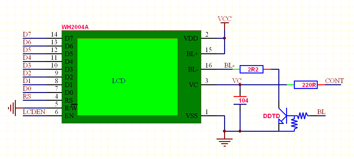
Fortunately character LCD displays use TTL logic thresholds so you can drive them easily from 3.3V logic. Tachyon has a complete LCD driver that supports dimming and digital contrast control and control characters etc. It also supports big digits for 4 line displays.
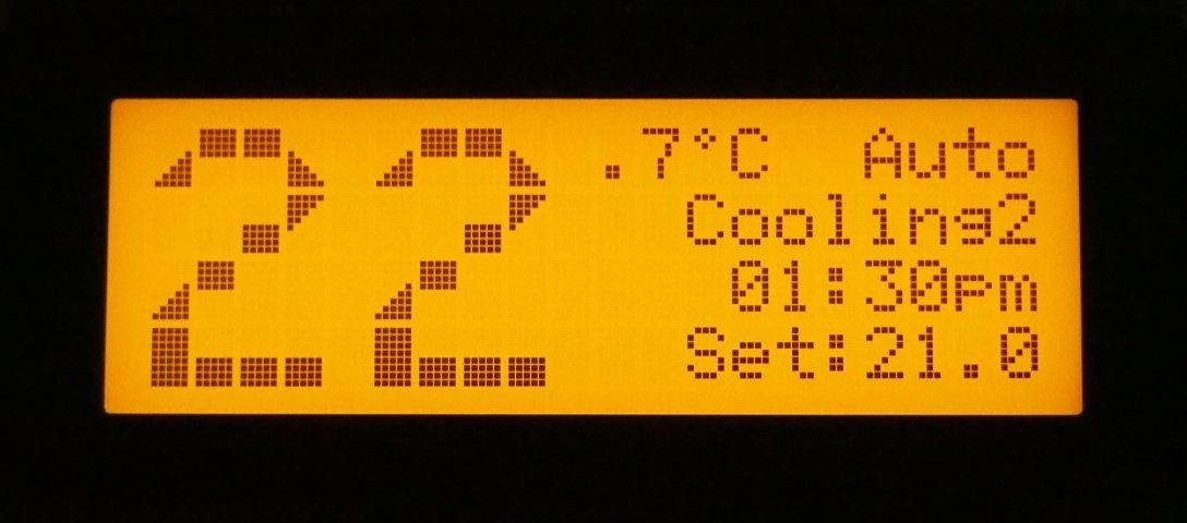
You can divert output to this device and you can use 2 or 4 line displays etc.
There is no need to worry about any delays etc but I think I connected the display in 8-bit mode as I have found 4-bit mode can glitch and lose nibble synch. You won't need to worry about resistors on the data lines either since there is never a need to read from the display because instruction delays are compensated for in software.
Look for CHARLCD.FTH and you can configure your hardware using LCDPINS like this:
--- ch ln bl vc ce rw rs d &20.4.18.14 &17.16.15.0 LCDPINSBob mentioned this is meant for a radio. The real challenge is to integrate all of the code pieces together in a complete application and that calls for a top down approach, I think.
I need to understand the requirements I would have for a radio in terms of user experience like for example I wouldn't like to transmit when I tune the radio but I would also like for the radio to "know" when I'm finished with tuning and dim a display when it's dark or light it up a bit when in gets brighter around. I need to separate the "must have" features from the "nice to have" ones. Not every feature can be added later on easily...