

Loading ... Done - but the program does not run.
 Programmichiere
Posts: 6
Programmichiere
Posts: 6
Hello, I'm trying to load my first program (the hello world example).
No error when compiling and loading, but the program does not run.
Can anyone tell me what I'm doing wrong?
forums.parallax.com/discussion/download/126524/prima%20registrazione%20schermo-2019-04-23_15.34.55.mp4
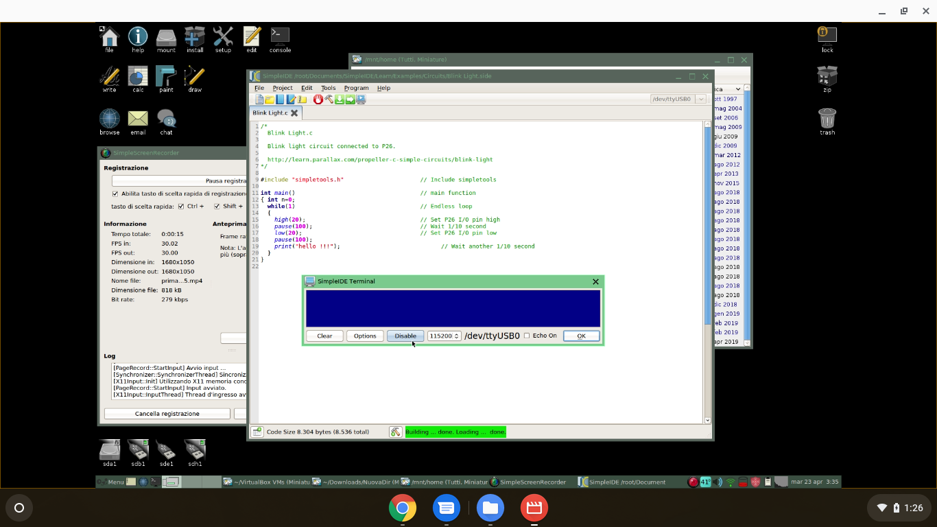
ModEdit: Image attached summarising the video clip
No error when compiling and loading, but the program does not run.
Can anyone tell me what I'm doing wrong?
forums.parallax.com/discussion/download/126524/prima%20registrazione%20schermo-2019-04-23_15.34.55.mp4
ModEdit: Image attached summarising the video clip
Comments
Useful shell commands are:
unfortunately that is not the problem, I am logged in as root.
root# groups
root tty disk audio lp dialout kmem video floppy cdrom tape tty plugdev lpadmin
The usb-serial converter works fine, and if I connect rx to tx, I can read what I write on the terminal.
There is a little hammer icon bottom-middle of SimpleIDE, clicking this will give you the build status. Here's what I get when clicking the Run-with-Terminal button:
EDIT: Attached a screenshot of it running
It's possible there is an issue with DTR line causing too many resets of the propeller and thereby wiping out any download in RAM. With it stored in EEPROM, a reset will still run what's been downloaded.
Also do those high() and low() methods automatically set the dira register for the I/O pins as outputs? If not, I'd think that'd need to be done first, before toggling the output state.
EDIT: Sorry, disregard - glossed over the fact that this is a pre-made example from the learn.parallax.com site...
I can't load to eprom because I have no one.
The chip is mounted on a breadboard,maybe I should have specified it previously,
but I'm assuming the program is loaded correctly, because the ide give no errors and no warnings.
if I disconnect any pin the ide give errors, then the chip is dialoguing with the IDE.
I'm trying to reset manually the reset pin , but without positive results.
propeller-elf-gcc -v GCC 4.6.1 (propellergcc_v1_0_0_2411)
propeller-elf-gcc -I . -L . -I /root/SimpleIDE/Learn/Simple Libraries/Utility/libsimpletools -L /root/SimpleIDE/Learn/Simple Libraries/Utility/libsimpletools/cmm/ -I /root/SimpleIDE/Learn/Simple Libraries/TextDevices/libsimpletext -L /root/SimpleIDE/Learn/Simple Libraries/TextDevices/libsimpletext/cmm/ -I /root/SimpleIDE/Learn/Simple Libraries/Protocol/libsimplei2c -L /root/SimpleIDE/Learn/Simple Libraries/Protocol/libsimplei2c/cmm/ -o cmm/Welcome.elf -Os -mcmm -m32bit-doubles -fno-exceptions -std=c99 Welcome.c -lm -lsimpletools -lsimpletext -lsimplei2c -lm -lsimpletools -lsimpletext -lm -lsimpletools -lm
propeller-load -s cmm/Welcome.elf
propeller-elf-objdump -h cmm/Welcome.elf
Done. Build Succeeded!
propeller-load -Dreset=dtr -I /opt/parallax/propeller-load/ -b ACTIVITYBOARD cmm/Welcome.elf -r -p /dev/ttyUSB0Propeller Version 1 on /dev/ttyUSB0
Loading cmm/Welcome.elf to hub memory
8140 bytes sent
Verifying RAM ...
OK
Is this a Propeller Mini, Propeller FLiP, or a DIP chip?
Voltage drops could cause this.
The Mini and FLiP modules have the caps built in.
I tried with and without crystal.
Could the baud rate be influenced by the crystal frequency?
It's no mentioned in the simpletext.h File Reference
Hope you have a 5MHz crystal and the bypass caps and all power and ground and BOE connected.
BTW I note that your code posted toggles P20 but the comment says P26.
Regarding the crystal, although a crystal is optional for some things, it is needed for stable comport emulation. And I'm not sure but the compiler defaults probably assume a 5 MHz part. Any other frequency will likely need software adjustments to suit. I'm not familiar enough with the Prop1 to answer this any more precisely, sorry.
If you are using a crystal at some frequency other than 5MHz you will need to create a board configuration file with the correct frequency. We can help you create the board config file if needed.
OK, what is not running, all or part? If the LED flashes, something is running, so no text, check the terminal settings or scope the serial channel to see if there is any activity. There is an LED in the code, why? Visual indication of the code running. Compile and load and what happened, LED (not)blinking, (no)serial neither or both? Need to know the test setup is correct before debugging the code.
What if it is a handshake issue with the serial line? Seen that by many people who think they can just hook up a null modem cable with Rx, Tx and GND. Maybe it works maybe not. Were the rts/cts or dtr/dsr looped back on each end of the null modem cable? If your computer is waiting on either of these, you will not transfer in either direction. So, you can't just say 9600,n,8,1. Your system may be set to use flow control and / or hardware handshake. Code may be correctly running and appear failed due to your computer configuration. Another process may have control of the port. Not likely the problem here as the OP said he can loop back his Rx with Tx and see characters typed. (Beware that this test will look fine if terminal is set for half duplex mode when you are really seeing what "should" be sent. If set to half duplex and really sending/receiving then a b c will look like aa bb cc..... )
Between +3.3V and ground.
Things will not work right without these capacitors....
I'm using the dip chip alone with a 47uF cap between vss and vcc and 15uF caps on either side of the chip.all electrolytic.
I think the crystal was faulty, tried with a 3.5 MHz one and got some garbled text over the serial, then the chip is alive.
Now I'm reading the datasheet to learn something about clock and crystal registers an how to write them inside the C program.
Thank you all for helping me solve this problem.
Propeller uses it's internal clock for programming, but will rely on the correct code settings for either the internal or external crystal to operate the code.
This might be why you are successfully programming the device, but cannot use the terminal features- as the terminal will require that the clock settings are set correctly in your code. If you change from 5MHz to 3.5MHz crystal, for example, then you will need a different clock setting in the code.
We are all guessing quite a lot here because we cannot see a picture of your circuit. If you could share that, then I'd think you'd get the right solution immediately.
But in the meantime, I would repeat the advice above that one (or many) of the following is the most likely culprit:
I think this makes a nice summary for other uses who find the same issues you have, so I hope you don't mind me listing these here.
I have a hunch that your code setting for the crystal might be the issue though. SimpleIDE sets that automatically based on the board type you select, so the code might be assuming a 5MHz crystal. With the CLK (etc..) commands you can override the settings for your own requirements.
Here is the photos, even if it would have been more useful earlier, as suggested.
Note that I still have to replace caps and add an eprom.
A big error was to assume that the chip would recognize the crystal frequency by itself . I should have read the manual more carefully,
in fact on page 14 it is "clearly" written how the CLK register must be set.
it would be nice, I found some info about boards cfg files and surprisingly the serial now works
# Propeller activity board configuration.
clkfreq: 3579545 <--- crystal freq
clkmode: 42 <--- decimal value of 00101010
baudrate: 115200
[ . . . . . ]
I would like to understand how to use asm instruction and get the same result writing directly the to the ram.
is writing to BYTE[4] equals to write CLKSET register?
is BYTE[4] intended as fifth byte in the ram memory?
do { \ _CLKFREQ = (frequency); \ _CLKMODE = (mode); \ __builtin_propeller_clkset(mode); \ } while(0)Note this is HUB RAM, as each Cog (CPU) has its' own RAM, called Cog RAM which can only be addressed as longs (4 bytes). Therefore its' address is $000-$1FF and where last/top 16 longs are Special Registers that your program will set to do certain things, such as reading/writing to the I/O pins.
It's great that you have straddled the Prop to take power from one side to the other
Another point is your crystal. Lots of ICs require "tuning" caps usually from both crystal pins to ground. The prop provides these internally
Next, the crystal is specified to have a capacitance range - it's about 18-22pF IIRC, so your Crystal should match this. Unless your building something extremely delicate, then this mostly will not matter. Within the nominal range of these sized crystals, all that will matter is that your frequency will be a very tiny amount out. Nothing you are likely to do at this stage will matter, certainly not serial communications.
So, go enjoy yourself