

Fun with Goertzel
 cgracey
Posts: 14,323
cgracey
Posts: 14,323
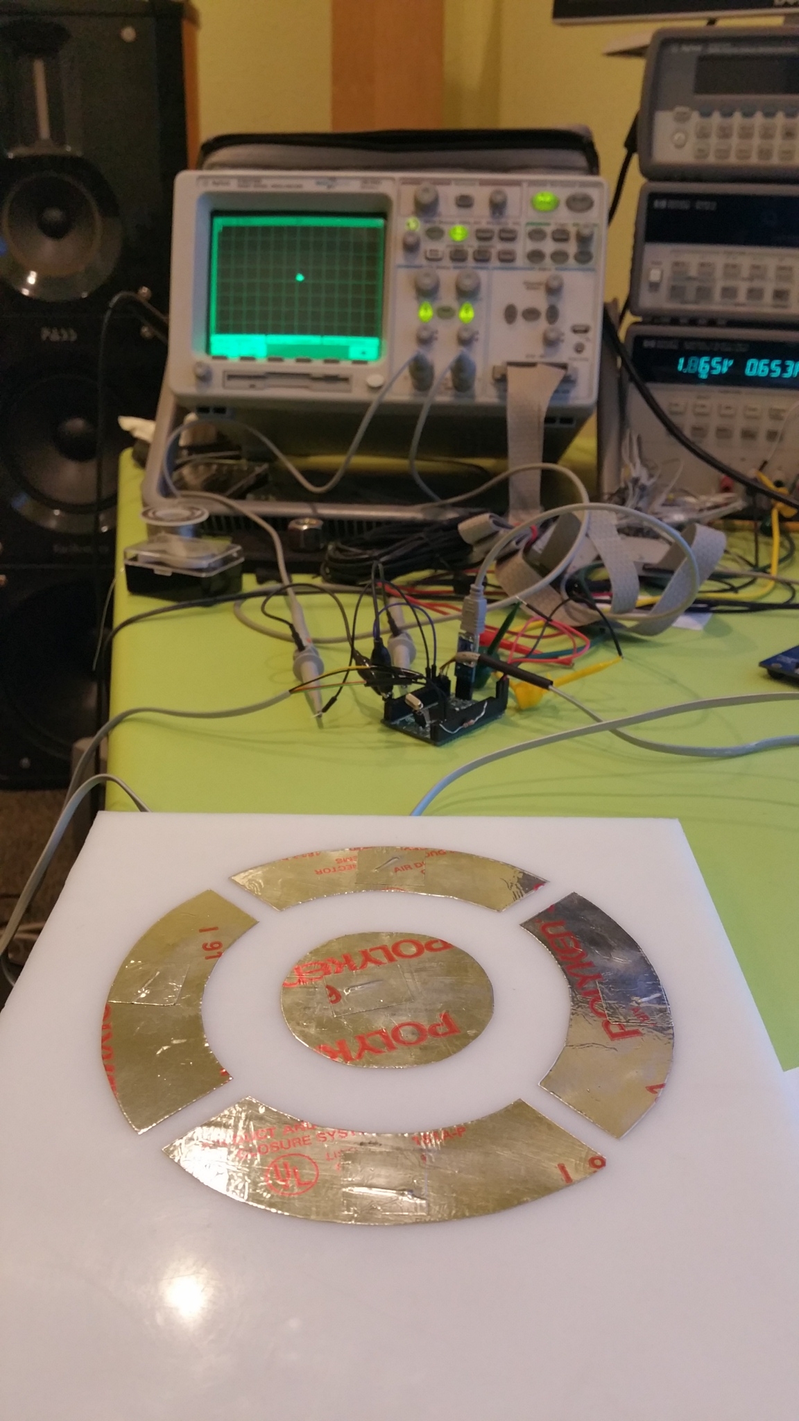
I did an experiment to see if we could get X,Y position sensing through the air using a 4-phase RF signal.
I had the Goertzel output 1.2MHz at 0/90/180/270 degrees over four adjacent pins.
Another pin is used as the Goertzel input in 100x-magnification ADC mode.
I used a piece of HDPE and some aluminum tape to make a quadrature output ring and a center receiver node. The four 1.2MHz phases are connected to the quadrature sections and the center pad goes to the 100x ADC pin.
It works amazingly well. At first, I was moving my hand over it and it was very lobe-like, but today I realized that if I move my hand or finger perpendicularly, the coupling becomes ideal. We are measuring 1,200 cycles of 1.2MHz, so we are getting 1000 samples per second.
Please see the attached .mp4 video.
This is really exciting to me. I was hoping things like this would be possible, but could only implement the building blocks during the design phase. And now, it works!!!
Here is the code. Really simple:
con		gtzpin = 0
		adcpin = 32
		xpin = 8
		ypin = 9
		shift = 10
		clock_freq = 260_000_000.0
		signal_freq = 1_200_000.0
		cycles = 1200

' set up clock

dat		org

		hubset	##%1_000000_0000001100_1111_10_00	'enable crystal+PLL, stay in 20MHz+ mode
		waitx	##20_000_000/100			'wait ~10ms for crystal+PLL to stabilize
		hubset	##%1_000000_0000001100_1111_10_11	'now switch to PLL

' make a sin/cos table in LUT

		mov	z,#$1FF			'make 512-sample sin/cos table in lut
sincos		mov	x,z			'get angle into top 9 bits of x
		shl	x,#32-9
		qrotate	#$7F,x			'get sin/cos of (ro,theta)
		getqx	x			'get cos
		getqy	y			'get sin
		setbyte	x,y,#1			'get sin into byte1, cos in byte0
		setword	x,x,#1			'copy bytes 1,0 to 3,2
		xor	x,##$8080		'make bytes 1,0 positive (not used, but could be)
		wrlut	x,z			'write sin:cos:psin:pcos into lut bottom bytes
		djnf	z,#sincos		'make 512 samples

' set up I/O

		wrpin	dacmode,#gtzpin+0	'enable DAC pins for 0/90/180/270-degree Goertzel phases
		wrpin	dacmode,#gtzpin+1
		wrpin	dacmode,#gtzpin+2
		wrpin	dacmode,#gtzpin+3
		drvl	#gtzpin+0
		drvl	#gtzpin+1
		drvl	#gtzpin+2
		drvl	#gtzpin+3

		wrpin	adcmode,#adcpin		'enable ADC pin for Goertzel input

		drvl	#xpin			'enable X,Y DAC pins for X,Y scope display
		drvl	#ypin

' Do Goertzel loop, show accumulations on X,Y

loop		setq	f1			'ready frequency
		xcont	m1,#0			'issue Goertzel command

		getxacc	x			'get last Goertzel X,Y accumulations, X first
		mov	y,0			'Y comes through source

		cmpsub	cal,#1		wc	'use 10th reading as calibrated zero point
	if_c	mov	xcal,x
	if_c	mov	ycal,y

		sub	x,xcal			'subtract zero point
		sub	y,ycal

		sar	x,#shift		'shift down results and make unsigned for X,Y scope input
		sar	y,#shift
		xor	x,#$80
		xor	y,#$80

		setbyte	xymode,x,#1		'X pin update
		wrpin	xymode,#xpin

		setbyte	xymode,y,#1		'Y pin update
		wrpin	xymode,#ypin

		jmp	#loop			'loop

' Data

xymode		long	%0000_0000_000_1011100000000_00_00000_0		'DAC for x,y scope outputs (0-2V)
adcmode		long	%0000_0000_000_1001110000000_00_00000_0		'Goertzel ADC input, 100x mode
dacmode		long	%0000_0000_000_1010000000000_01_00000_0		'Goertzel DAC ouputs
f1		long	round(signal_freq/clock_freq*float($80000000))	'Goertzel frequency
m1		long	%0000_1110<<24 + adcpin<<17 + cycles		'Goertzel mode, DAC !1/1/!0/0 output
cal		long	9

xcal		res	1
ycal		res	1
x		res	1
y		res	1
z		res	1
Comments
I need to post you some of this magic stuff called geofoil, you can create those structures using a laser printer
Well done Chip, this makes it all worthwhile, right?
Yesterday, I made this thing and I couldn't make much sense of its response. Realizing how the RF couples and that my hand needed to be perpendicular, not parallel to the plane suddenly made it do what I was hoping it would do.
The difference, though, is their technique is encoded in silicon, whereas with the P2 you're able to sweep frequencies, add pins, and play with structure/form, and add code/video inside the same IC.
Fun times ahead.
Yes.
I'm trying to think of other useful configurations, also, if there are any other useful modes I should provide hardware support for.
Might it be useful to have a Goertzel sub-mode where rather than use a single pin at a time for input, maybe incorporate a 2nd, 3rd, or 4th for summation and/or difference schemes, so that the 1-bit ADC values are added/subtracted together to form a >1-bit sample to act as a multiplier for the sine and cosine LUT values that get MAC'd? I wonder what kind of extra functionality that could afford.
Supporting two pins would be easy.:
PinA + PinB
%00 = -1
%01 = 0
%10 = 0
%11 = +1
PinA - PinB
%00 = 0
%01 = -1
%10 = +1
%11 = 0
As it is now, one pin works like this:
Pin
%0 = -1
%1 = 1
Two-pin sum and difference modes will get added. That will enable relative and cumulative measurements between pins.
I suppose two pins gets you some special measurements, but is it a case of diminishing return to add more?
I suspect after that it gets too specialized / consumes too much logic.
Where are you stuffing these extra mode bits?
Into the S operand of the Goertzel command. Only 12 of 32 bits are currently used.
Adding pins into a summation is easy, the trouble with difference is what gets subtracted from what.
I guess the other option is to set -1/ +1 coefficients into a matrix that extends beyond the immediate neighbor
%EEEEEEEE = relative pin enables
0 = ignore pin
1 = sum pin
You could invert the pin via bit 31 of the WRPIN setting to cause subtraction, instead of addition.
This would result in a sin/cos multiplier of -4 to 4. Still simple to implement:
8H + 0L = +4
7H + 1L = +3
6H + 2L = +2
5H + 3L = +1
4H + 4L = 0
3H + 5L = -1
2H + 6L = -2
1H + 7L = -3
0H + 8L = -4
I did notice that at 100x mag ADC mode, there is some slight adjacent-pin coupling. That's 90% from PCB layout, though, I think.
Should we just set up for 8 input pins?
%EEEEEEEE_DDDDDDDD
E = enable pin for sum/difference inclusion
D = 0 for sum, 1 for difference
That would do it. I'd need to enhance the multiplier computation to accommodate 0..8 pins. That -4..+4 range would need to become -8..+8 to allow for odd numbers of pins.
Good work!
That scheme is nice and simple. No chance of this stuff being on a critical path, right?
BTW, this kind of application is exactly why I want a P2!
Chip, your using foil at the pins and your hand to interfere with the field, if I'm understanding this right.
If I wanted to have a feedback mechanism for a moving object (controlled by the same P2) I'm assuming I would need a foil detector connected to the ADC. Then another "foil" pad connected to ground (??? I'm assuming your body is grounding the signal) mounted on the moving object.
Does that sound about right??
j
No need for foil or ground, necessarily. You just need conductors to establish a field and then some pin or pins to read the field strength and phase. there's got to be millions of ways to set this up.
I think a lot of people's thinking is informed by what they've seen with capacitive sensors which charge and discharge and measure time. In those cases, large conductive areas are needed to detect charge. This is just field strength. Wires are all that are needed. It's like establishing potentiometers in air.
This is pretty simple, but it's going to take time to get acclimated to thinking about, in terms of how it can be set up and exploited.
j
The .mp4 is attached to the initial post. You need to download it and play it.
I've been expanding the streamer to handle ADC input and DAC output. So this effort is part of that.
It might be way too slow, but worth a try.
No. Look at the code. Everything is flexible.
That suggests you could detect directionality with very few inputs and math.
If you had 1 emitter and 4 receivers, you can detect something passing in 2 different axes.
You might want to lower the emitter frequency though, 1.2Mhz is a little high and could cause interference. 125Khz is what RFID uses IIRC.
You could potentially use this for non-optical motion detection, and probably through walls (with a large enough antenna).
I know there is research into using the 2.4Ghz microwaves emitted by Wifi to "see through walls", but I don't know how accurate they can get. I'm sure it requires some fancy hardware to make work.