

PropMou8e - Propeller-based maze-solving micromouse competition robot
 Microcontrolled
Posts: 2,461
Microcontrolled
Posts: 2,461
Wasn't sure weather to post this here or the Customer Projects board, but I figured here would be best since the project isn't *quite* completed yet and I'd like to use this thread to log my progress and discuss some design stuff if anyone's interested.
Introducing my side project over 1 year in the making: The PropMou8e!
The PropMou8e is a micromouse competition robot that I've designed to compete for WVU Tech in the IEEE R2 Student conference. I designed one last year that was less then successful, and this redesign takes the challenges introduced by that one and attempts to circumvent them. Last year's robot was designed, built, and programmed about 1 month before the competition. It was big, heavy, and fairly limited in terms of sensors, using only wheel encoders and 3 PING sensors. This redesign is smaller, lighter, and packed with more sensors than we really need. Before I get into the design, though, let's clear up what we're trying to do.
What is a micromouse competition?
RoboGames has a complete set of rules available here. Essentially, the goal is to design, build and program a robot capable of solving a maze, and navigating toward the center as quickly as possible. Multiple passes are allowed during the timeframe, which for our competition lies at 10 minutes. The maze is 16x16 tiles, with each tile being 18x18cm. The robot is technically allowed to be up to 25x25cm, though the smaller the better for navigation purposes. The strategy we're working on implementing is a methodical solving of the maze using the Flood Fill algorithm, then a fast run using the solved maze data. Theoretically, both of these runs should complete in 10 minutes, with time to spare for potential missed runs.
The Hardware
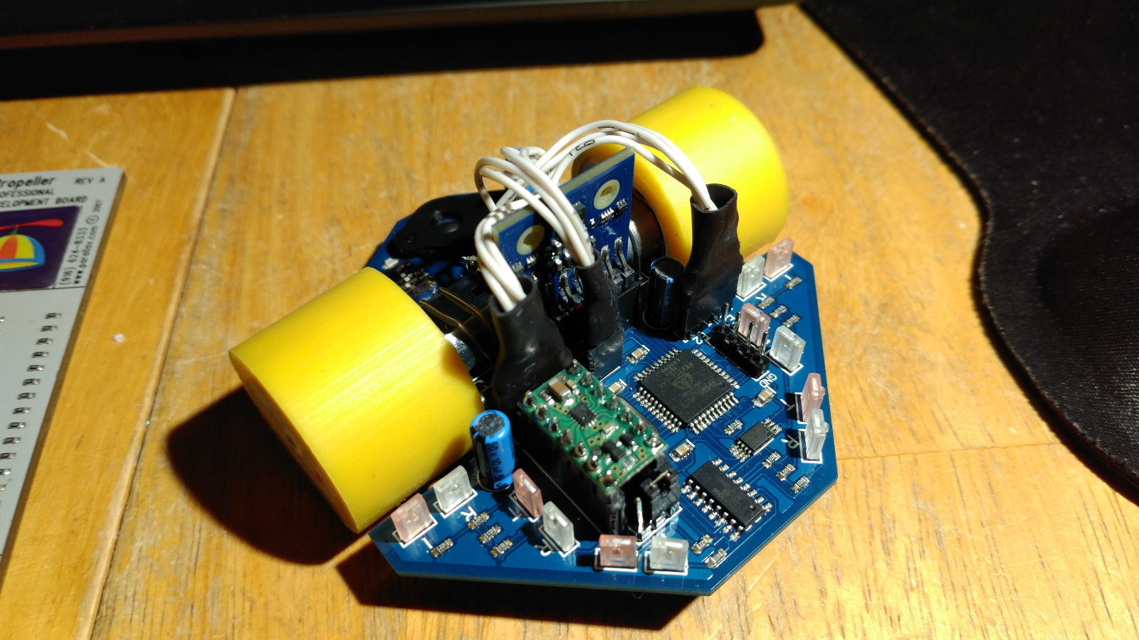
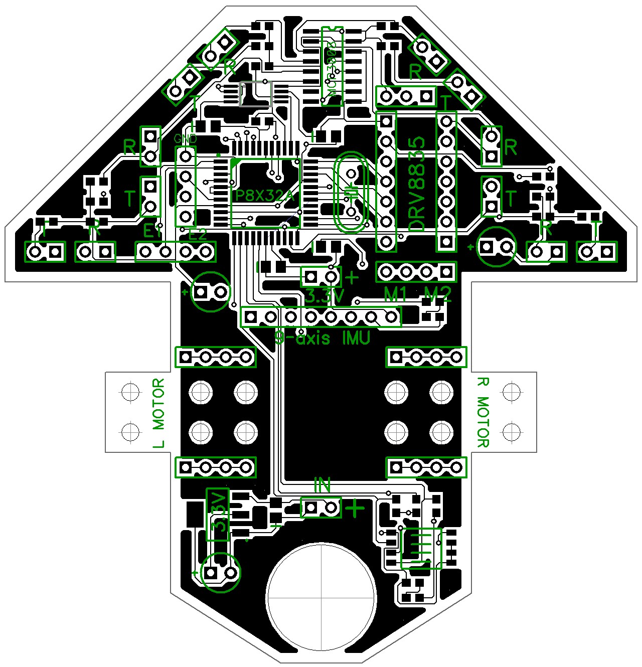
The hardware has been designed from the ground up to be small, light, and packed with sensors. The current prototype features 6 IR sensor pairs, the Parallax 9-axis IMU, and a pair of magnetic wheel encoders. The wheels used are the Pololu micro metal gearmotors, and the encoders are the Pololu hall effect pair designed for use with the motors. An external ADC is used to read the IR sensors, and a light motor driver is used to drive the gearmotors. The board is powered by 2 1S 3.7V LiPo cells (not shown in the photos), and the processor is, of course, the Propeller. The whole thing is mounted on a custom PCB, shown below.
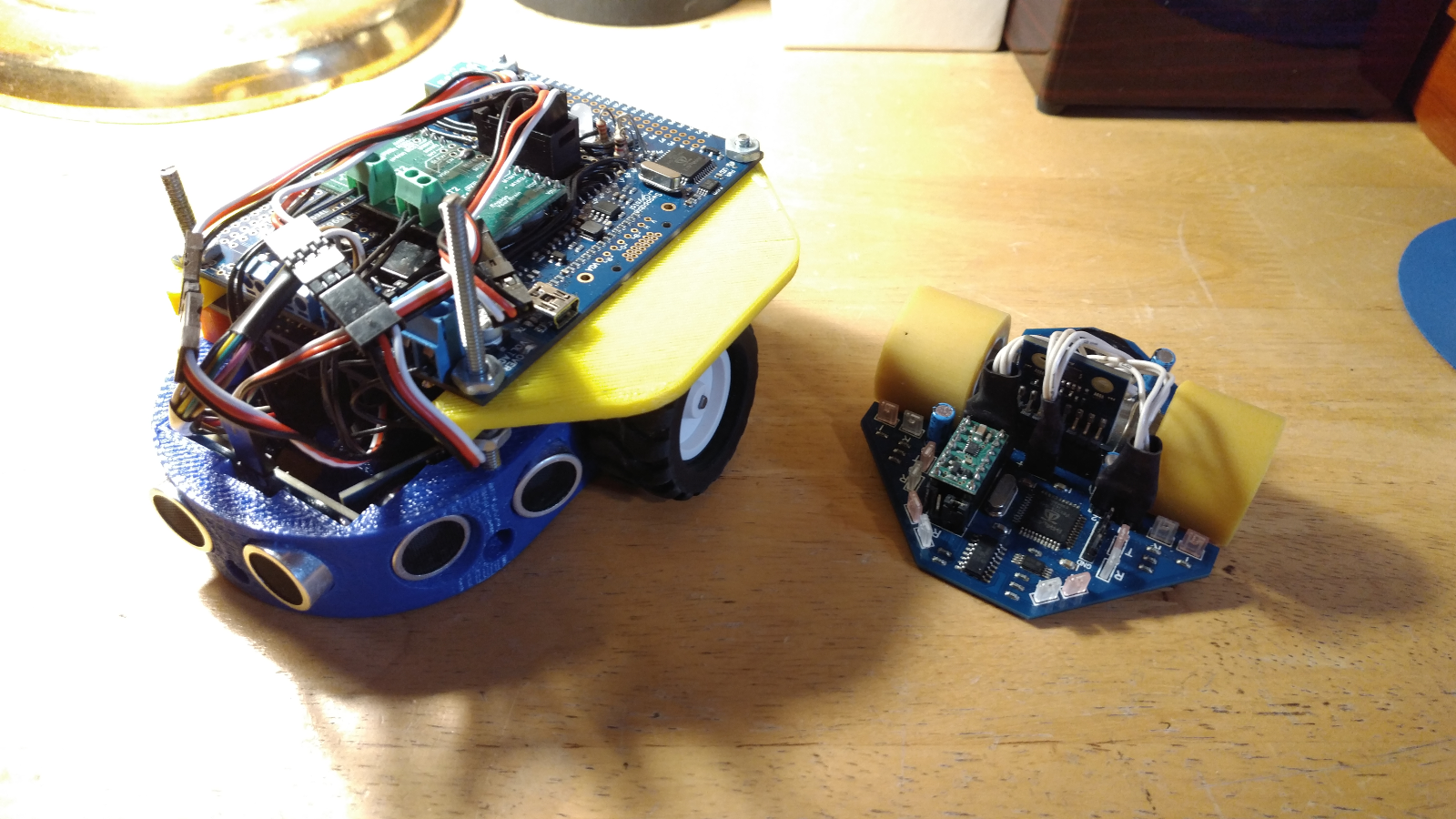
The hardware is the most major improvement from the previous form. Here's V1 from last year shown next to the current prototype.
I'm pretty fond of the 3D printed chassis I made for V1, but it wasn't well suited for the competition. Our failure came as a result of getting stuck between 2 walls (think Austin-Powers style) when one of the bumpers slammed into the wall too hard. Getting wedged shouldn't be as much of a problem for the new guy!
One of the primary problems last year was knowing what direction we were facing, and correcting ourselves if it was incorrect. The IMU is largely serving to help this, giving us at worst a rough idea of where we're facing, and at best being able to straighten us up completely. The placement of the IR sensors allow us to "square up" with walls both forward facing and from the side, and give us the ability of straightening up should we get misaligned in the maze. The encoders provide a feedback loop to the IMU and IR sensors, and help us calibrate the motors to go straight with minimum sensor correction.
This prototype works pretty well, though I've designed a newer PCB that I'm going to get made when I order the IEEE group's SumoBot PCB to save on shipping. It's largely the same, but slightly smaller, provides bracket mounts for the motors, proper plugs for the LiPos, and an Xbee socket for wireless debugging.
The software
The software is still in progress, though a lot has been done. The flood-fill solver works independent of the bot when fed pre-rendered wall data, and is a much neater code than last year. The drivers for all the peripherals are written and working, and the sensor data is being read and stored in respective cogs. The multicore nature of the Propeller is highly appreciated for this project, as the sensors can be continually read and processed while the bot is navigating. I developed a basic C#.NET program for debugging that graphs and displays all the sensor data, as shown.
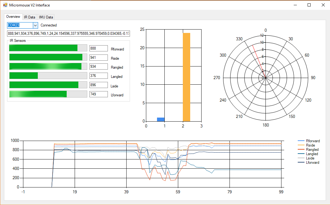
The other tabs break down the graphs by sensor, and the IMU by axis. The gyro angles are determined based on CLK cycles read over time and the angular velocity, so it suffers from *some* drift, but it's capable of calibrating itself using the magnometer while the motors are disabled. I've currently got it to the point where I can calibrate the angles and motors, and turn the bot to a specified angle. I've written it to go a specified distance forward or backward, but my last pair of LiPos died and I forgot the charger at my apartment before I left for break, so I'll have to see if it works on Monday.
I'll try to update this thread as I progress on this project. This semester is my last, and I'm only pulling 9 credit hours, so I'm hoping that I should have plenty of time to work on this *and* senior design.
I'm open to any questions or suggestions, I'm still a novice so any experience is appreciated. Thanks!
Introducing my side project over 1 year in the making: The PropMou8e!
The PropMou8e is a micromouse competition robot that I've designed to compete for WVU Tech in the IEEE R2 Student conference. I designed one last year that was less then successful, and this redesign takes the challenges introduced by that one and attempts to circumvent them. Last year's robot was designed, built, and programmed about 1 month before the competition. It was big, heavy, and fairly limited in terms of sensors, using only wheel encoders and 3 PING sensors. This redesign is smaller, lighter, and packed with more sensors than we really need. Before I get into the design, though, let's clear up what we're trying to do.
What is a micromouse competition?
RoboGames has a complete set of rules available here. Essentially, the goal is to design, build and program a robot capable of solving a maze, and navigating toward the center as quickly as possible. Multiple passes are allowed during the timeframe, which for our competition lies at 10 minutes. The maze is 16x16 tiles, with each tile being 18x18cm. The robot is technically allowed to be up to 25x25cm, though the smaller the better for navigation purposes. The strategy we're working on implementing is a methodical solving of the maze using the Flood Fill algorithm, then a fast run using the solved maze data. Theoretically, both of these runs should complete in 10 minutes, with time to spare for potential missed runs.
The Hardware
The hardware has been designed from the ground up to be small, light, and packed with sensors. The current prototype features 6 IR sensor pairs, the Parallax 9-axis IMU, and a pair of magnetic wheel encoders. The wheels used are the Pololu micro metal gearmotors, and the encoders are the Pololu hall effect pair designed for use with the motors. An external ADC is used to read the IR sensors, and a light motor driver is used to drive the gearmotors. The board is powered by 2 1S 3.7V LiPo cells (not shown in the photos), and the processor is, of course, the Propeller. The whole thing is mounted on a custom PCB, shown below.
The hardware is the most major improvement from the previous form. Here's V1 from last year shown next to the current prototype.
I'm pretty fond of the 3D printed chassis I made for V1, but it wasn't well suited for the competition. Our failure came as a result of getting stuck between 2 walls (think Austin-Powers style) when one of the bumpers slammed into the wall too hard. Getting wedged shouldn't be as much of a problem for the new guy!
One of the primary problems last year was knowing what direction we were facing, and correcting ourselves if it was incorrect. The IMU is largely serving to help this, giving us at worst a rough idea of where we're facing, and at best being able to straighten us up completely. The placement of the IR sensors allow us to "square up" with walls both forward facing and from the side, and give us the ability of straightening up should we get misaligned in the maze. The encoders provide a feedback loop to the IMU and IR sensors, and help us calibrate the motors to go straight with minimum sensor correction.
This prototype works pretty well, though I've designed a newer PCB that I'm going to get made when I order the IEEE group's SumoBot PCB to save on shipping. It's largely the same, but slightly smaller, provides bracket mounts for the motors, proper plugs for the LiPos, and an Xbee socket for wireless debugging.
The software
The software is still in progress, though a lot has been done. The flood-fill solver works independent of the bot when fed pre-rendered wall data, and is a much neater code than last year. The drivers for all the peripherals are written and working, and the sensor data is being read and stored in respective cogs. The multicore nature of the Propeller is highly appreciated for this project, as the sensors can be continually read and processed while the bot is navigating. I developed a basic C#.NET program for debugging that graphs and displays all the sensor data, as shown.
The other tabs break down the graphs by sensor, and the IMU by axis. The gyro angles are determined based on CLK cycles read over time and the angular velocity, so it suffers from *some* drift, but it's capable of calibrating itself using the magnometer while the motors are disabled. I've currently got it to the point where I can calibrate the angles and motors, and turn the bot to a specified angle. I've written it to go a specified distance forward or backward, but my last pair of LiPos died and I forgot the charger at my apartment before I left for break, so I'll have to see if it works on Monday.
I'll try to update this thread as I progress on this project. This semester is my last, and I'm only pulling 9 credit hours, so I'm hoping that I should have plenty of time to work on this *and* senior design.
I'm open to any questions or suggestions, I'm still a novice so any experience is appreciated. Thanks!
Comments
Clearly a lot of work. Congrats!
Have you built a mini maze for practising?
What are the IR sensors, and how do you get analog-values from them ?
It doesn't give much technical info on the bot, but I did a fun little "recipe gif" style video of building it here.
@Addington: I have built a mini-maze for practice! It only really breaks regulation in that the walls are half the regulation width, but it has the advantage that it's entirely machinable and disassembles completely. I don't have it built right now, but this should give a good idea of the pieces and how it all goes together. I cut the pieces out of 5.5mm thick plywood underlayment with a 40W laser cutter, and gave them about 2 coats of paint.
I can upload the vector files if anyone else wants to make them, I've made enough for a 5x5 maze but I'm thinking of making more this year for a full 9x9 practice maze. (with the goal at center, it lets you practice a proper solving run.
@jmg: For the IR sensors I use a pairs of Osram emitters and receivers. To get the analog values I use a 10-bit 8-channel SPI ADC, which I interface using the simpletools SPI driver. The inputs are connected to power, with a pulldown resistor being controlled by the phototransistor.
For testing, it is OK as long as the passageways between walls are 168mm wide. No problem here.
Your practice maze is easy to dismantle, store, transport and set up. Great.
Unfortunately, it didn't end up making it to the center of the maze. Only the first place bot managed, and it did so using a random path algorithm rather than a maze solving algorithm. This is generally considered a high-risk move, as random-nav bots rarely make it to the center and in the case of judging based on incomplete runs, they generally score low for not implementing a proper solving algorithm. There were a couple other random-nav bots, but their downfall was lower speed, so high-speed random-nav must not be a terrible strategy.
It was judged positively for
- Using a proper solving algorithm (Flood fill)
- Utilizing a self correcting strategy with IR/gyroscope (even though it didn't work as well as I would like)
- Using a "specialized" multi-core microcontroller (yay Propeller! The only non-Arduino there)
- Custom hardware/board
The primary downfall of the device was the reliance on IR sensors. Even with the 3D-printed covers, the ambient light would cause the sensors to incorrectly determine walls and obstacles, and the IR correction would occasionally be plagued by random spikes causing the motors to correct sharply. The difference between wall/no wall would be about ~30 via the decimal readings, but depending on the light, the readings could fluctuate by hundreds. I wrote a calibration routine to get the average wall/no-wall values, but it wasn't 100% reliable due to different shadows/etc. This could have been avoided by averaging multiple values and checking against redundant sensors (many readings had possible closed-loop setups) but programming was delayed due to time. I ended up finishing up most of the nav code in the last 2 weeks (!) before the contest, leaving some bugs unsolved and some segments of spaghetti code. Luckily while I was working on the initial hardware design I had a friend help me write the flood fill code, so that library will be well documented and (mostly) clean. I'll be posting the code once I get his permission to share it.
I'll post any more updates as they come, but at least until finals are over this project will sit as "retired". I'll graduate in a few weeks so this will be my last competition. Most of the work in the next few weeks will be to promote this design at the Innovators Fair and the WV IEEE Student Awards Section, basically trying to earn it any credentials we can.
Thanks to everyone interested in this project!
I bet Ken & Parallax (and the rest of us) would love more details of your wonderful Propeller robot. Do you have any video?
I glad to see micromouse competitions are still going on. I recall seeing a micromouse competition at a Personal Computer Show in London in the 1980's. One very young guy had built a bot consisting of a Sinclair Spectrum strapped to a plastic lunch box with elastic bands which in turn held the motors, wheels, sensors and batteries. I have no idea how well he did but I admired the initiative. Another entry was by some guys from the Marconi company where I worked. They normal designed things for the aerospace industry so their bot was constructed from precision machined aircraft grade aluminium parts. An impressive construction but it did not do very well.