

Reading DCC data using a propeller on track. (digital model railway control)
 Clock Loop
Posts: 2,069
Clock Loop
Posts: 2,069
(NOTE ALL MY POSTS HERE WILL BE EDITED TO REDUCE PICTURE SIZE)
My old setup before setting up the 8 zone test track.
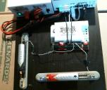 https://forums.parallax.com/discussion/download/121974/TestRig.jpg
This thread is dedicated to my investigations on dcc railroad transponding, with a goal to use the propeller to diagnose dcc track problems and data, and cast that data to a parallax WX for viewing on any telnet ansi terminal running capable device. (all mobiles have term apps)
This will get its power from the track but NOT send data to it, just get data from it, at least not at first, that would be nice, but will take time to figure out.
I know a few others have done this, but they haven't really included all the juicy photos, video, schematics, programs, and discussion that is really needed for a topic like DCC.
So I am tackling that with propscope screen shots and video, plus desktop capture of jmri plus more.
I am using a setup that will enable you to follow along pretty well as its developed.
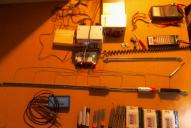 https://forums.parallax.com/discussion/download/121972/test2.jpg
Currently I am using a propscope to get the data I need, and it has served me well, with emphasis, that I haven't even touched a current sensor yet, but will be. (to display the transponder data, better)
I don't know alot about dcc. But thats changing fast.
I can see the transponding on the propscope when triggering from the transponder led in the locomotive.
If I change this led to a weaker resistor, and one that is allowing much more current, I can then see that on the rails, as a slight dip.
That also affects the transponder receiver, it increases the "volume" of the transponder by pulling more current.
I am having problems with a specific transponder model causing havok on the transponder receiver. (i think its the transponder model, because another model doesn't do this)
The transponder that is causing the problem, causes the same problem for the working transponders, so i suspect its in the transponder receiver that the problem can be found.
IF I look at the transponder receiver current sense, with my own sensitive current sense device, this will tell me what data is REALLY going down the pipe.
But all this is so hard to get going and do and figure out the tools and parts (current sensor) etc i need.. so.. i figure why not make something that can go on the rail and assist in my investigation.
To get started on CONTENT, I have a few videos showing jmri running trains and it also shows the transponder messages coming from the transponder receiver that are constantly swapping.
This video shows a jmri screen shot of a train going around doing transponding.

The next two show the transponder reporting two trains going around the track, but their transponders are randomly getting confused.


And this video is a miracle, it actually transponded two trains at the same time properly, until 1 point where it reported it wrong once, and then corrected.
I reconnected some layout wires and that happened. It turns out it was a fluke. Because as soon as I restarted the layout, it was back.

So I disconnected the layout and wired up a test station.
Back to the transponder resistor, I found that different decoders have different transponder output levels on the same track, so this presents the pull on the transponder receiver differently, and that, might be where my problem will show.
I have tried different resistors, and they do make a difference. My transponder receiver is new, so its very possible that its simply a firmware bug.
I am using it as an excuse to understand the dcc system, and then, the equipment that I have already purchased.
I would like to repair it and not leave it in others hands, or trash, since stuff dies all the time with 'lectrics....
To do that, I need to start understanding it, so follow along if you wish.
I suggest you get a dcc system and a prop scope and follow along!
The next video/images here will show a capture of the transponder on the rails and on the transponder wire(thats the trigger)
I still haven't figured out what the data is and all that, to determine what is in fact going over the rails.
For now how about a video of a 3D railroad game I own. Rendered on a overkill system. (system specs are in the youtube comments)

My old setup before setting up the 8 zone test track.
https://forums.parallax.com/discussion/download/121974/TestRig.jpg
This thread is dedicated to my investigations on dcc railroad transponding, with a goal to use the propeller to diagnose dcc track problems and data, and cast that data to a parallax WX for viewing on any telnet ansi terminal running capable device. (all mobiles have term apps)
This will get its power from the track but NOT send data to it, just get data from it, at least not at first, that would be nice, but will take time to figure out.
I know a few others have done this, but they haven't really included all the juicy photos, video, schematics, programs, and discussion that is really needed for a topic like DCC.
So I am tackling that with propscope screen shots and video, plus desktop capture of jmri plus more.
I am using a setup that will enable you to follow along pretty well as its developed.
https://forums.parallax.com/discussion/download/121972/test2.jpg
Currently I am using a propscope to get the data I need, and it has served me well, with emphasis, that I haven't even touched a current sensor yet, but will be. (to display the transponder data, better)
I don't know alot about dcc. But thats changing fast.
I can see the transponding on the propscope when triggering from the transponder led in the locomotive.
If I change this led to a weaker resistor, and one that is allowing much more current, I can then see that on the rails, as a slight dip.
That also affects the transponder receiver, it increases the "volume" of the transponder by pulling more current.
I am having problems with a specific transponder model causing havok on the transponder receiver. (i think its the transponder model, because another model doesn't do this)
The transponder that is causing the problem, causes the same problem for the working transponders, so i suspect its in the transponder receiver that the problem can be found.
IF I look at the transponder receiver current sense, with my own sensitive current sense device, this will tell me what data is REALLY going down the pipe.
But all this is so hard to get going and do and figure out the tools and parts (current sensor) etc i need.. so.. i figure why not make something that can go on the rail and assist in my investigation.
To get started on CONTENT, I have a few videos showing jmri running trains and it also shows the transponder messages coming from the transponder receiver that are constantly swapping.
This video shows a jmri screen shot of a train going around doing transponding.
The next two show the transponder reporting two trains going around the track, but their transponders are randomly getting confused.
And this video is a miracle, it actually transponded two trains at the same time properly, until 1 point where it reported it wrong once, and then corrected.
I reconnected some layout wires and that happened. It turns out it was a fluke. Because as soon as I restarted the layout, it was back.
So I disconnected the layout and wired up a test station.
Back to the transponder resistor, I found that different decoders have different transponder output levels on the same track, so this presents the pull on the transponder receiver differently, and that, might be where my problem will show.
I have tried different resistors, and they do make a difference. My transponder receiver is new, so its very possible that its simply a firmware bug.
I am using it as an excuse to understand the dcc system, and then, the equipment that I have already purchased.
I would like to repair it and not leave it in others hands, or trash, since stuff dies all the time with 'lectrics....
To do that, I need to start understanding it, so follow along if you wish.
I suggest you get a dcc system and a prop scope and follow along!
The next video/images here will show a capture of the transponder on the rails and on the transponder wire(thats the trigger)
I still haven't figured out what the data is and all that, to determine what is in fact going over the rails.
For now how about a video of a 3D railroad game I own. Rendered on a overkill system. (system specs are in the youtube comments)
Comments
Ok, so the blue line is the track wire that senses the transponder, (not the common wire).
The red line is the led that has the transponder on it, this shows the data that the loco is intending to send to the track.
I trigger off this LED wire, in the whole video.
I trigger off the track some, but not much.
WHAT you are seeing here is the data coming off the system when no throttle has been initiated, so technically the transponder is not active.
But those led pulses says that some kind of transponding of some sort is going on.
In the next video you will see the difference when transponding is activated.
https://forums.parallax.com/discussion/download/121975/Transponder Packet Repeat Length.jpg
Right now it looks like... every other bit is on, 0 1 0 1 0 1 0 1 The last bit goes high, this must be the stop bit. (the 9th bit)
LETS CALCULATE WHAT THAT IS.
First we need a binary to decimal to hex tool. You can search the web for one or go to this thread and read it.
it has some java tools that you can run once you configure java to allow the etools folder.
http://forums.parallax.com/discussion/81449/e-tools-html-java-script-electronic-design-tools-free-for-you
I do not know if its lsb or msb so the number,,
decimal(hex) its 85(0x55) , or 170(0xAA).
So this is a transponder in a rest, BUT the CV for the transponder is active.
Notice the extra "space" before the re transmission of the same data, either that can hold more data, and/or its just wait time for the next data window.
If I put an image of the 9 bits over that spot it fits perfectly, so the transponder sends a max of 16 bits per packet?
So this data is the result of an active but not "requested" or controlled by any throttle, transponder.
To capture these shots, I had to put the propscope in X10 mode, the track voltage is 14v.
And the led voltage is around 7.
So to capture the transponder going over the track better than a few spikes and dips on the blue line, I will eventually need a current sense device of some sort.
And that I will want to display somehow. Isolated from track,.. thats where the parallax wx comes into play, it will send my info to my wifi network.
https://forums.parallax.com/discussion/download/121976/DataRate.jpg
It shows 3.07 us, so 3us bit rate. lets see.
1 / 0.000003 = 333333.3333333333
So the transponder is running at 333,333 bps (the prop scope calculated 326khz, it would probably be accurate if there was a better way to manipulate the cursors and zoom/pan parts of the propscope software. Text based entry.
Anyway 333khz is pretty speedy.. I am not sure i would do current sense based data that fast...
Thats pretty fast i think, for current base sensing, did I do my math wrong... Ah well onward...
This image takes a shot of the 4 "windows" that the transponder will try to send its data in.
These 4 data bursts are identical in this shot, and will probably always be identical, they are most likely re-transmission of the transponder so it gets thru.
(but mine isn't so thats why im here)
https://forums.parallax.com/discussion/download/121979/4 packet window.jpg
This next shot shows something interesting, a NOTCH IN THE TRACK Line, at the end of that "4 transponder transmission window"...
Hmm wonder what that is...
https://forums.parallax.com/discussion/download/121980/4 packet window notch.jpg
This notch, it dosen't happen every packet window either, so that measurement on its cycle rate will be yet another thing to track down.
I too have had an interest in DCC, though it has been a few years since I was active in it.
Have you read all the support documents from NMRA and Digitrax? I think there is lots of info there.
I may dig into that, but from what I can tell these dcc devices are not actually that complicated.
The software is most of the complication, and that part is pretty locked down among manufacturers, i don't really need to pour through sheets of mind numbing hex addresses, .... Only to find missing information and standards that aren't updated since 1997..
Its bad when the maker is telling you to try stuff you already did.
They say nothings wrong. Its all me. So....
Nah, im gonna wiggle some pins with a scope and build most of my info base that way.
So. I will figure it out myself, with a scope, and testing logic fit for a vulcan.
"what happens when i short this zone out"
"what happens when I use a 1k resistor to short it, at 10k, a 100ohm, a 100kohm?"
"what happens if I inject noise?"
"what...."
etc.
And then you watch the data flow, and repeat. Once you are confident that data packet is due to a specific function, you make note and move on.
More post will be coming soon.
I was thinking about using a simple resistor current sensor since the transponder pulses are very low current, and the loco isn't doing anything with its motor, so the most power use at rest or transponding ... is the transponder.
I measured the decoders power usage at idle with its transponder going idle (this means its sending 01010101) its power use is 20ma PEAK.
A simple current sensor to use with the propscope, could be created using that info right?
Anyone have any simple suggestions? Remember, the rail is 16v AC. I can buy a sensitive hall effect sensor, and will, but for now...
If I plug in my values...
https://forums.parallax.com/discussion/download/121983/rctime.jpg
I come up with a capacitor of 0.006uF / 6nF / 6000pF
Time to see what I have in my parts pile.
The real test to see if my math is right, is to hook it up!
So if I make a shunt resistor, along with a rc circuit... could i measure the current pulses with the prop...
I may need an external function generator to charge the rc circuit... not sure.. the propscope has one,...
Seems like im looking at making a circuit here.. Hmm,, PCB ARTIST is free.. And easy.. http://www.4pcb.com/free-pcb-layout-software/
Once i get a schematic going, i will probably see how to do it.
Its amazing how powerful it is, having a computer schematic in front of you where you can connect parts in different ways and consider the consequences..
Time to do that.
If anyone has any ideas feel free to suggest it.
heh..
Since I can't edit previous posts to ADD IMAGES, I must keep making new posts to change or add that content.
I don't mind, if those are the limits of the forum, but don't get mad at me for posting so much.
This will help me figure out a circuit, since I am not dealing with a negative swinging signal anymore.
But beware, this circuit is not capable of running trains.. Do not do this if you don't know why you are doing it.
To get this info I disconnected any equipment I had on my command station (the thing that generates the rail power).
I simply monitored rail 1 and rail 2, and made measurements.
The first measurement is the smallest pulse found on the rail lines.
That would be its frequency, 56.6us is what my display shows.
I found an image on the internet that says what it SHOULD be,,
So, 58us and 100us pulses .. thats what I see..
NOTICE THERE IS NO track notch here.
The track notch, I can see now, is a direct part of the transponder reciever. Thats what is generating that notch in the rail voltage.
https://forums.parallax.com/discussion/download/121994/NoDecoder.jpg
Well, well, I see some important timing and triggering info here..
https://forums.parallax.com/discussion/download/121995/NoDecoder1.jpg
So I can see, that I can trigger from that Peak pulse that happens, I think that tells the loco WHEN to transmit its transponder.
One THING TO NOTICE, it doesn't look like before... Its not a COMPLETE rail profile, like when I had a decoder(loco, train) on the tracks.
Hmm...
Also, notice that the peak pulse is NOT on the other rail (the blue probe line).
That rail is the COMMON, and its linked through all zones, so its kinda unimportant, except to look for any noise or crosstalk on that line.
I haven't yet looked at the other zones to see if this peak pulse is located at the same timing spot on the rail or if its staggered among all zones.
If its staggered based on zone and also based on ID of the transponder receiver, that would be helpful at reducing crosstalk among all zones on the entire layout.
But well see if thats the case once i scope it out.
I found the simplest method of all. Just a shunt resistor. The prop scope can see it on the DECODER side of the shunt resistor.
I show 4 100ohm resistors in parallel = 25ohms.
The trigger is using the external DAC card for the propscope, on the decoder LED.
A trigger level of 1.1v is perfect for this setup and decoder, that trigger level will change between decoders and loco connection quality.
I will need to tweak it for each decoder test.
Remember that spike in the signal, well it disappears once a decoder is on the rails, then that rail profile shows up.
So triggering on that spike dosen't work, its sucked up by the decoder, so we must trigger on the decoder led.
Thats fine, it looks good.
YOu can see the rail profile is back, and YOU CAN SEE THE TRANSPONDER ON THE RAILS!!! HOORAY!
https://forums.parallax.com/discussion/download/121997/TransponderView1.jpg
And hmm, the transponder transmits when the rail profile at the end, is NOT there.. is this proper?
https://forums.parallax.com/discussion/download/121998/TransponderView2.jpg
So this next set of shots...
This loco number is 1405
Here it is, at idle, so the throttle has not turned the transponder id on yet.
https://forums.parallax.com/discussion/download/122000/1405idle.jpg
And here it is when I have put 1405 into the throttle, which activates its transponder id.
https://forums.parallax.com/discussion/download/122001/1405addressOnThrottle.jpg
IT CHANGED![que dramatic groundhog]
Here is a zoom up of the transponder bits.
https://forums.parallax.com/discussion/download/122002/1405addressOnThrottleZoom1.jpg
This zoom shows one transponder packet directly in the middle of the rail swing.
https://forums.parallax.com/discussion/download/122003/1405addressOnThrottleZoom2.jpg
And the same thing without the measurement in the way, notice the noise on the common rail (red)
https://forums.parallax.com/discussion/download/122004/1405addressOnThrottleZoom3.jpg
And a good measurement / zoom of a transponder bit, active on the rail.
https://forums.parallax.com/discussion/download/122005/1405addressOnThrottleZoom4.jpg
https://forums.parallax.com/discussion/download/122006/1405addressBinary.jpg
Its not the same as before, the 0 1 0 1 0 1 0 1 or decimal(hex) its 85(0x55) , or 170(0xAA).
Now its 0100 1101 , I noted the stop bit in the image scope shot.
Load up the number format converter...
decimal(hex) its 77(0x4d) , or 178(0xB2).
Hmm...
1405 in binary is 101 0111 1101 .
Hmm
Well, we can't fit that number into a single packet transmission window.
So the rest must be elsewhere...
WAIT I GOT IT.
Lets try transponding the NUMBER 1!!!!
So i need to change my transponder id on the programming track and in the throttle.
I suppose i can scope the programming track and see what it looks like while its programming.
Ohh, its so exciting, i know you are just weak at the knees.... to see whats next..
I think the address data is sent with other kinds of data, so it will take time to parse, great.
But I don't really need to parse the data, technically I can now monitor the data and see if it changes when the ID swapping/malfunction starts
But only when the transponders are idle. I need to test more to see if they are the same when active.
So that data, is a TAG.
It says to the transponder receiver, I have a transponder and its active.
It seems the data to tell JMRI what loco is in what zone, its still to early to tell if its the decoder or its the transponder receiver, that is doing the mixup.
Here is a desktop shot, you can see the two locos under test, the loco 1405 has the blue trigger probe attached to its transponder led.
And you can see its transponder TAG data stream, its the blue.
Notice the RED probe has no transponder TAG data stream, at that same time as the BLUE, actually you can't even see the RED transponder TAG yet..
This is two locos that have their transponders on and active, they do not transpond at the same time when active.
The Red transponds at a different time than the blue, they are zone 7 and 8.
This is proof the notch steps through each zone.
Timing is everything in this world, the smallest adjustment of the scope trigger and it will "hook" and bam, you magically see the part of a data stream you thought you'd never capture without a DSO.
Should this be moved to customer projects?
Jim
I was thinking the same thing yesterday, but it's up to Clock Loop. I'll move it if he wants.
This thread will not be easy on the eyes, its a development thread, for the prop, for this specific use.
In the past when we didn't have a project subforum, I just created a new thread in the appropriate cpu subforum with a neat title, description, and all needed schematics and files in the first thread.
I do have some examples of this, for propeller devices I have made in the past, I usually have a development thread in the appropriate cpu subforum, and then another thread in that same subforum with the first post containing all needed info to re-create the project.
That completed thread with all content in the first post, would probably be the thread that should be in the projects subforum once I complete the development.
This thread is an attempt to make the propeller chip interface with the nmra standard(and more since transponding is extra), and document it for others sure, but mostly for me.
The code I create will be all propeller, and the schematics.
At first this thread will only be using a prop in the form of a propscope to gather info.
Then I will be slowly assembling my diagnostic circuit that will probably have a few separate different "sections" to test for various different track functionality and problems.
For some reason rarely do people do this anymore... develop a thing with a development thread or log.. and then make a complete project thread... once its done!
Really, what most do.. is attach some snippet of code(if even that, lol), and a quick summary of what it does.. and mabee some bad lit phone camera shot of a haphazardly wired breadboard.
And you are LUCKY if you get a schematic, which is always missing with the code, for some reason...
So just keep it in the prop subforum. It may never reach project status, if I don't get past the discovery stage I am on now.
Once I make a new thread of the complete project, Where ever it is, I will probably upload all its content to hackaday, and link to the development thread and completed projects threads BOTH.
Then it will stay in Prop1. Thanks.
But I normally do that with threads.. its fun, and makes it more interesting to the reader.
BUT I don't have any prop code here yet...
I know yer excited to try this on your dcc layout, but slow down, im only human.
I will also need to come up with a circuit to get and store the track power for the prop...
...plus take the pulses from the track and prep them for voltage level/data interpretation by the prop.
Then add propeller transponding, with some additional circuit that will draw current from rails, simulating the transponder signal...
So that can be tested also...
IVE GOT SOME WORK AHEAD OF ME!
I may try animated gifs, now that i found a simple and opensource program to help me make them...
https://sourceforge.net/projects/gifapp/
Now, if you have a propscope, this animated gif might make you think you can push the controls...
Add a railroad sound to that animated gif, and you have... something... not sure what..
Is it possible that the transponder bits are actually done exactly the same way as the regular, slower rail data!?
...
So If we re-look at this regular rail data info, it says the short bits are 1 and long bits are zero.
AND the bit requires a full cycle to be considered a bit.
So DO NOT interpret the data as STRAIGHT SERIAL, its NOT!
INSTEAD, interpret the transponder data , as a mini version of the track data, based on pulse length.
So now if I go back and try to calculate what data is being sent over the transponder with this new info....
I will take a few different transponder measurements and check it out, and see if im right.
But knowing this, the transponder data "window" has a very limited amount of data it can fit, ones are short, zeros are long, so the more zeros the less data can fit in the same amount of time, this makes predictable cpu timing FUN!
So the transponder and receiver must have a code matrix of bit slice data, great more ghosts in the machine.
NO MATTER, ghosts are found by putting sheets over their heads..
So if we put a sheet over the transponder data and don't care what the data means, just care when its different, and note the difference, and what you did to make it different.
The NMRA site has some (OLD) info about testing decoder boards, by throwing specific data packets at it ...
So ill go over it and make sure to consider those kind of tests...
But its based on the parallel port.. not how im interfacing.
So I will consider all the nmra stuff as I go.
DCC Conformance Testing Procedures
Baseline Test Procedures in .pdf format (Adobe Acrobat)
https://www.nmra.org/sites/default/files/standards/sandrp/DCC_Documents/baseline.pdf
Locomotive Decoder Test Procedures in .pdf format (Adobe Acrobat)
https://www.nmra.org/sites/default/files/standards/sandrp/DCC_Documents/dcc_decoder_test_procedure_rev_d1.pdf
Accessory Decoder Test Procedures in .pdf format (Adobe Acrobat)
https://www.nmra.org/sites/default/files/acc-proc.pdf
Command Station Test Procedures in .pdf format (Adobe Acrobat)
https://www.nmra.org/sites/default/files/dcs-procv3.pdf
And some IMPORTANT... regular bit and voltage data...
https://www.nmra.org/sites/default/files/standards/sandrp/pdf/s-9.1_electrical_standards_2006.pdf
And naturally the packet info.
https://www.nmra.org/sites/default/files/s-92-2004-07.pdf
The entire list.
https://www.nmra.org/index-nmra-standards-and-recommended-practices
So yes, using this info to build the code and such, is needed.
But im still focused on my transponder issue.
I don't know for sure of the transponders cascade between each zone, and if they do, great, how does it work.
The loco in each zone has a single transponder message, "ACTIVE". And this in data is 101.
If two locomotives are in the same area, do they conflict? Do they send the same transponder message?
IF the locos are sending the same transponder message even if they have different ids, how does the transponder receiver know what id they are?
The loco must be sending the transponder at a specific time, which tells the transponder receiver what loco id that loco has.
IF this is even remotely close to how it works, then the transponder receiver has firmware or hardware problems that is causing the transponder id swapping.
I suppose the decoder could be confusing the timing up on when to chirp its own transponder, and that, can be found in time with enough bit monitoring.
Its still too hard to say if its the decoder or receiver.
The decoder could be seeing the wrong time on when to chirp its transponder, which would tell the receiver its the wrong loco, and really, possibly any loco in the system.
And I AM seeing that happen...
I can select a loco on my throttle that isn't a real decoder, and the transponder receiver will eventually say that my "ghost" loco is located in the spot a real transponder is found.
Thats how cross talk is possible....., the transponder chirp, being the same, gets across zones, and chirps at the wrong time in the wrong zone, tells the transponder receiver that its located in that zone.
Im seeing a loco that is chirping at the wrong time?
This would make a loco I selected with a throttle, but didn't exist on my layout, start reporting as being located in a zone it was not in. EXACTLY!
THATS ME!!!
So understanding now, how the transponding system works i think, what I have is a locomotive that is reading data from the rail that either tells it to chirp its transponder at the wrong time, or it has a bug that tells it to chrip its transponder at the wrong time.
So test this I would need to start sending false data to the loco, along with false transponder triggering to see when the transponder chrips its active pulses.
I can also now test the transponder receiver by simply sending the transponder ACTIVE signal at the right time.
But to do either I need to now completely parse the data in one of the zones on the transponder receiver
If I completely replace the transponder receiver with my "ROLL MY OWN", then I have total control.
Thats a bit harder.. Since I have a pretty complex wave form, a dac with some kinda h bridge could make things happen pretty fast.
A serial interface dac might be something to think about.... http://www.ti.com/product/dac714
It has +/- 10v so pushing the gates of a +/-16v hbridge should work?
I am also going to want to closely monitor the result of my hbridge on the rails, so i will need a two channel ADC.....
If I can find a +/- 20v high bit adc, that should cover most scales..
Hmm well, I suppose having a +/- 10v ADC http://www.analog.com/en/products/analog-to-digital-converters/ad7734.html#product-overview
Nice 16.5v input tolerant means spikes aren't an issue, and 50v max input means serious rail trouble still is ok before safety clamping must happen.
4 channel, means I can monitor my hbridge gates while monitoring my hbridge output, since im gonna need to tweak the dac output to the hbridge gates.
Something I like to do is monitor and manipulate semiconductor junctions.
I see both those parts are too slow for what I am doing here, gotta search more, ...
Using a opamp type front to the adc/dac is probably inevitable, so using lower voltages is not a big deal.
All that is fancy and all, but i suppose looking at what you have available, and part reduction is nice..
SEMICONDUCTOR LOCOMOTION?
Who needs a current sensor, or shunt resistor when you have a semiconductor junction?
The only way to tell if its possible with what you have chosen for parts, and your voltages, is try it.
But since this is a diagnostic device, I want to design it with as much self monitoring and protection as i can.
So having sturdy parts, esd and high voltage tolerant, ... etc.
So many ways to go... so little time.
Hmm, I need to think about all this now.
Need some thinking music, NO WORDS.