

Repurposing a broken Servo360
 Phil Pilgrim (PhiPi)
Posts: 23,514
Phil Pilgrim (PhiPi)
Posts: 23,514
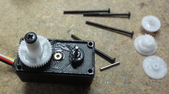
In a process that can only be described as abuse, I managed to chip a gear tooth in my new Servo360, rendering it kinda cluncky. Rather than discarding it, I realized that its internal encoder still worked just fine but would work better with a free-running shaft, which meant discarding the gear train. That much was easy to do: just remove the four long screws holding everything together, pop the gears out, and put it back together. The only tricky part was getting the middle gear out, since it's underneath the output shaft gear. But that was remedied by removing the middle gear's shaft and just sliding it out. Here's what was left:
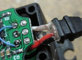
Then I thought it would be nice to eliminate the fourth wire lead, leaving a nice compact three-wire cable for the encoder. That's when things got -- well -- messy. Here's what the wiring looked like before the mods I made:
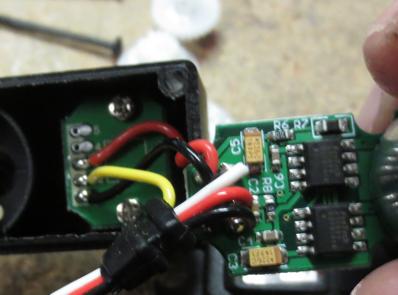
It would have been simple to remove the yellow wire and the white wire and to solder the white wire where the yellow one was. And that's what I should've done, but I had more ambitious plans. I thought it would be cool to remove the motor/driver assembly to play with later on and proceeded to remove both sets of red and black wires and to solder the ones from the cable directly onto the encoder board. After doing so, I realized that the two sets of red wires were not connected together. There's a voltage regulator on the motor driver board that provides the encoder's power. No biggie, I thought: I'll just always run the encoder on 5 volts. Then I looked at the datasheet for the Servo360, which specifies that the PWM output is 0 and 3.3V. Nuts!
But maybe the encoder can still run on 5V? I looked up the datasheet for AS5600 Hall-effect chip used in the encoder. Lo and behold! It can run on 5V. But there's a catch: to do so it has to be wired differently, along with an additional filter cap. So I checked for a tell-tale short between the chip's pins 1 and 2 and, indeed, it was there. So no chance to run it on 5V without some major surgery. Nuts, again!
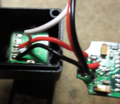
So I undid all the wiring I had so patiently soldered and put everything back the way it was, except for soldering the white wire to the encoder board:
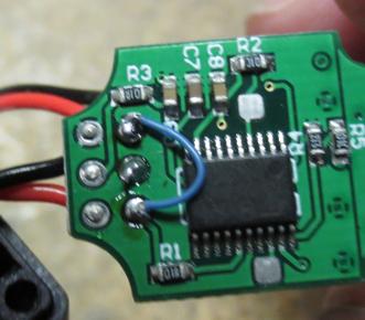
Finally, for good measure, I jumpered the original pad for the white wire to ground to keep the motor controller from responding to noise:
That's all for the wiring. However, since the yellow wire was completely removed, the remaining three wires were loose in the little rubber strain relief. So to remedy that, I added a dab of hot-melt glue to the inside to keep them from pulling out:
From there, it was just a matter of reassembling and testing. Amazingly it worked. Now I have a nice absolute encoder with a ball-bearing output shaft that turns freely! And it's still a bargain at the Servo360's retail price!
-Phil
Then I thought it would be nice to eliminate the fourth wire lead, leaving a nice compact three-wire cable for the encoder. That's when things got -- well -- messy. Here's what the wiring looked like before the mods I made:
It would have been simple to remove the yellow wire and the white wire and to solder the white wire where the yellow one was. And that's what I should've done, but I had more ambitious plans. I thought it would be cool to remove the motor/driver assembly to play with later on and proceeded to remove both sets of red and black wires and to solder the ones from the cable directly onto the encoder board. After doing so, I realized that the two sets of red wires were not connected together. There's a voltage regulator on the motor driver board that provides the encoder's power. No biggie, I thought: I'll just always run the encoder on 5 volts. Then I looked at the datasheet for the Servo360, which specifies that the PWM output is 0 and 3.3V. Nuts!
But maybe the encoder can still run on 5V? I looked up the datasheet for AS5600 Hall-effect chip used in the encoder. Lo and behold! It can run on 5V. But there's a catch: to do so it has to be wired differently, along with an additional filter cap. So I checked for a tell-tale short between the chip's pins 1 and 2 and, indeed, it was there. So no chance to run it on 5V without some major surgery. Nuts, again!
So I undid all the wiring I had so patiently soldered and put everything back the way it was, except for soldering the white wire to the encoder board:
Finally, for good measure, I jumpered the original pad for the white wire to ground to keep the motor controller from responding to noise:
That's all for the wiring. However, since the yellow wire was completely removed, the remaining three wires were loose in the little rubber strain relief. So to remedy that, I added a dab of hot-melt glue to the inside to keep them from pulling out:
From there, it was just a matter of reassembling and testing. Amazingly it worked. Now I have a nice absolute encoder with a ball-bearing output shaft that turns freely! And it's still a bargain at the Servo360's retail price!
-Phil
Comments
I'd be interested in looking at the output shaft side under the encoder board...
-Phil
Thanks for documenting this for us tinkerers that were curious.....
For now.
Biding its time...
It would have to be diametrically (cross-wise) magnetized to work for this function, but I was wondering if it was a disc/cylinder or ring magnet. I was thinking for price it could be a ceramic ring magnet, but those would likely need to be larger to provide a good magnetic field. Can you determine the length of the magnet, and does it have a shiny or matte appearance?
Maybe the sensor chip has good reliability in low-Gauss fields. You can reprogram the thing, you know! Did they bring out any of the I2C pins to solder pads?
-Phil
1-Black-Gnd
2-Yellow-Output
3-Red-VCC
4-NC
5-NC
Are 4 and 5 I2C pads ?
Can someone from Parallax confirm ?
You can reprogram the output pin to be analog, or use I2C to read the position.
I put mine back together before the question was asked and don't want to take it apart again. 'Sorry.
-Phil
Thanks for the honest response, i didn't want to cause you any trouble.
Looking to your picture it seems i need to take the screws to see the other side, i don't feel confident that i can put it back, i don't know if it's necessary a specific alignment.
I hope someone from parallax could provide more details.
-Phil
The datasheet doesn't suggest a stringent alignment beyond the physical mounting restraints, but I wouldn't want to encourage anyone to take theirs apart unless it's a bad/damaged servo, just in case they use a fancy jig or something!
The screw holes in the PCB just fit the screws: they're not slots. So the alignment has to be built into the board layout. Having to use an alignment jig would only add to the assembly cost.
Beyond that, you'd be right. Any major non-centricity between the magnet and the chip would result in non-linearities in the output.
-Phil
I'm hoping that those are the I2C I/O pins...
Also, I'm not sure why the circuit board is soldered to the motor...
The servos I've opened up the circuit board occupies the whole top of the servo and I think is held in by the four long screws.
This one is different...