

CNC - I may be crazy but...
 ManAtWork
Posts: 2,367
ManAtWork
Posts: 2,367
in Propeller 1
Ok, I have to admit that I've stolen the title from Idbruce. But I couldn't resist. I think I'm at least as crazy as him. Look at this. It's my definition of a CNC machine.
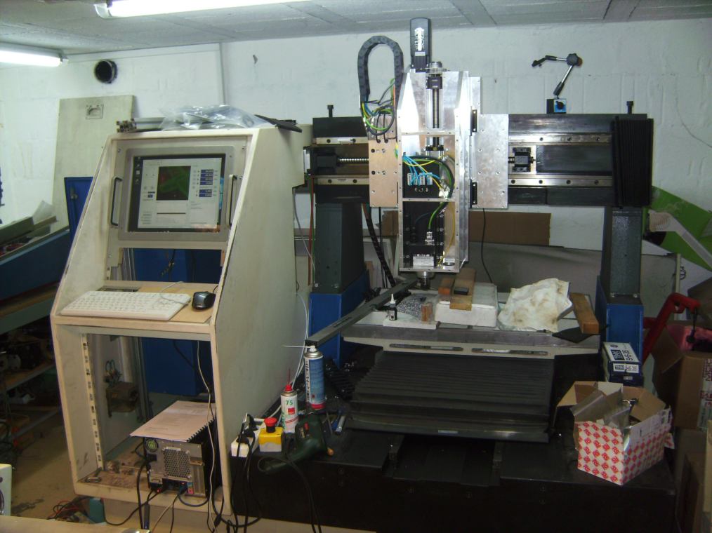
It's a "Schmoll Compact". "Compact" means, it's one of the smaller models, weighting over 2 tons . It was actually a PCB drilling machine. The mechanics was in very good condition but I removed the whole controller and the DC servos. I replaced them with MOOG AC servos, 2HP for the X and Y axis and 1HP for the Z axis. I had to rebuild the Z axis because the original axis had too little travel to do any useful work other than drilling PCB holes.
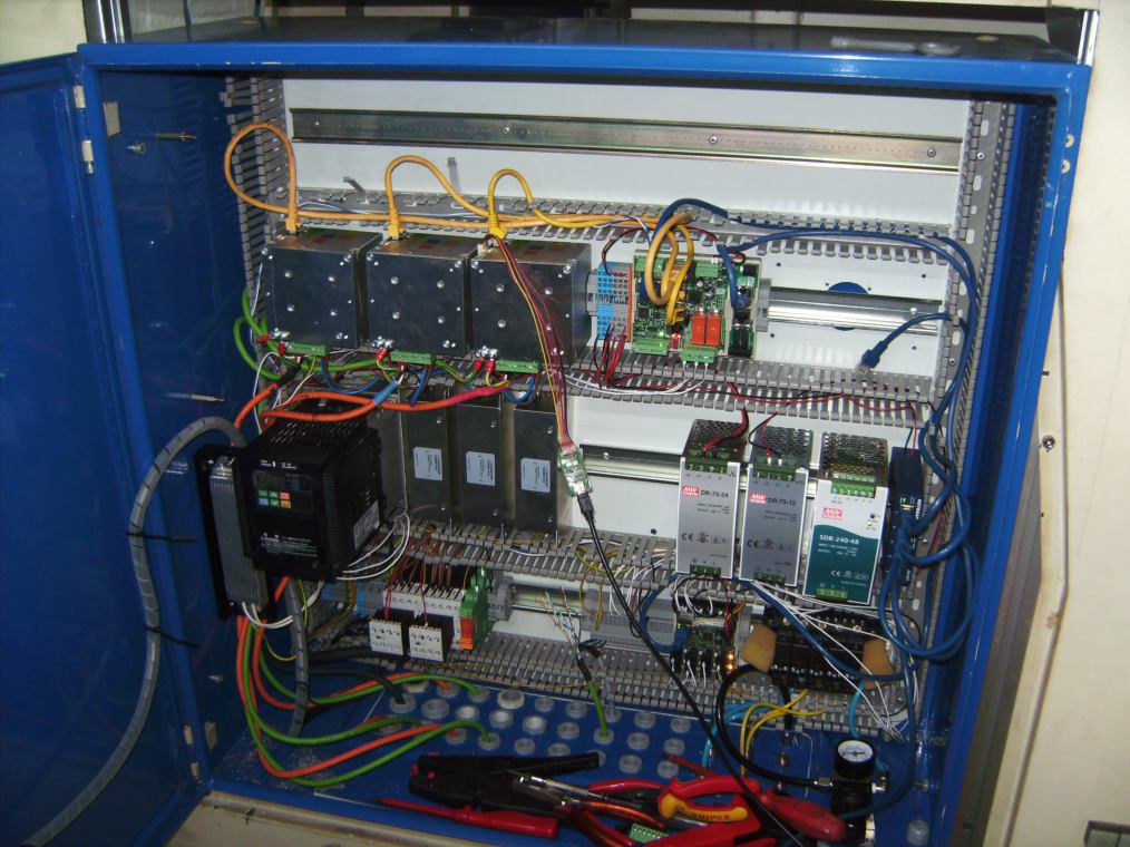
This is the electrical cabinet. Except for the Power supplies and the VFD for the main spindle I build everything from scratch. Guess how many propellers are in there.
This is one of the servo motors:
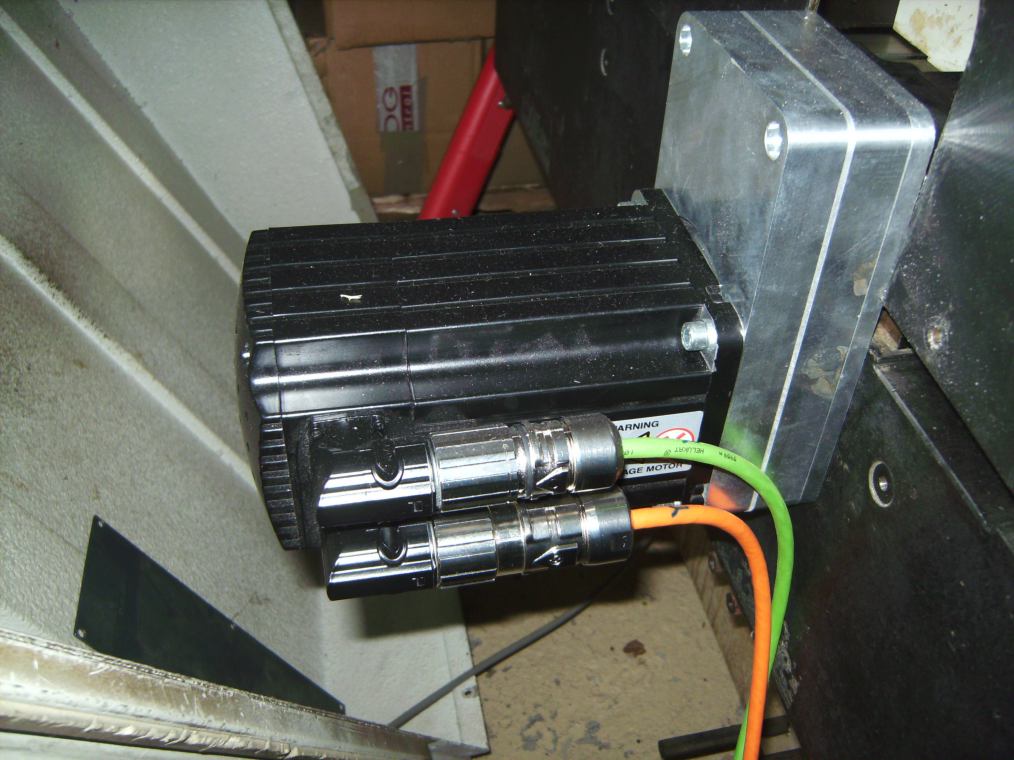
Feedback from the servos (resolvers) is already working. I still have to run a few wires through the cable chains to the limit switches and the magnetic brake of the Z motor. I hope I can power up the servo controllers for the first time, next week.
It's a "Schmoll Compact". "Compact" means, it's one of the smaller models, weighting over 2 tons
This is the electrical cabinet. Except for the Power supplies and the VFD for the main spindle I build everything from scratch. Guess how many propellers are in there.
This is one of the servo motors:
Feedback from the servos (resolvers) is already working. I still have to run a few wires through the cable chains to the limit switches and the magnetic brake of the Z motor. I hope I can power up the servo controllers for the first time, next week.
Comments
I thought that title looked very familiar
Looks nice, but what are you going to use it for? Milling? Drilling?
There is one propeller chip in each servo amplifier (A in the picture)
The other two can be seen directly if you look closer (P). One is on the axis controller which receives commands from the PC via LAN (blue cable) and generates step/direction signals for the servo drives (yellow cables).
The last one is on the IO board (P) in the second picture.
It's also connected to the LAN (N = network switch) and controls the solenoid valves (S) for the tool changer and mist coolant, relays and contactors.
So alltogether there are five propeller chips. Other components are:
V = VFD for the spindle motor
R = braking resistor
F = EMI filters
PP = optoisolated prog plug
A PC or a raspberyy pi can do this much better. At the moment I'm using a standard desktop PC just because I had one standing around. If everything is ready I think I'll replace it with a NUC that would fit nicely inside the cabinet.
Where the heck have you been?
I can't access your site and I also emailed you. Good to see you are still around.
yes, I had to close the web shop to have more time for creative work, again. However, things still always take longer than planned.
I still have some problems with the servo tuning. The drives are designed to run up to 12m/min at the X and Y axis and up to 6m/min at Z. At the moments they fault out with following error if I go faster than 5 and 3m/min. But for the rest I'm quite happy with the result.
Next thing to do is to get the main spindle working and to get a T-slot table for workpiece fixture.
The theoretical approach to servo-sizing never worked for me so I calculate and double-up....LOL
You fault out with no load?
Hey Nicolas,
I just remembered why I was trying to contact you.
You were offering a range of brushless drives & motors at a really good price that I couldn't get close to, here in the UK.
Do you know of a manufacturer of basic, analogue drives, without the built-in motion-control capability (that I have no use for)?
I am currently using ABB's MicroFlex range but they are still more sophisticated than what I need. If my customer should need to replace a failed drive, I don't want him to go through the bother of having to set a bunch of parameters.
I run my servo's in torque mode so the most I need is something with current scaling and even that, I can live without.
I am talking 2KW range.
Also a supplier of BLMs?
Recent update... I use the machine a lot for milling aluminium parts like motor flanges or heatsinks for stepper motor drivers.
As you can see in the closeup it makes nice, shiny surfaces. Cutting parameters: 6mm endmill, single flute, 18000rpm, feedrate 1500mm/min, depth per cut 3mm, total depth 15mm
That is some beautiful stuff, ManAtWork.
I don't know what the metric equivalent is, but for a finish pass I like max RPM, 0.001" per tooth, and 0.010" depth.
Since your using an endmill I don't what the best stepover is but a guess would be 75% or 50% of the cutter diameter.
I also like to 'hard' anodize (ANSI Type III) 0.001" or 0.002" thick because regular anodize (ANSI Type II) will wear away.
On gluing fixtures razor blades will wear away and scratch the surface especially in steps where glue loves to accumulate.
Latest update: added an automatic tool changer

")
Video too short....I grabbed a coffee to watch and then found it was only eight seconds