

Propeller P1V CD quality audio over I2S (and now for regular Propellers/SIDCog/AYCog/SNECog patches)
 rogloh
Posts: 6,390
rogloh
Posts: 6,390
A while ago I purchased a nice 24 bit I2S digital audio DAC output module (the CS4344 based PMOD I2S module from Digilent) and in the last few days I finally got around to interfacing it with the P1V Verilog to get some sound output quality better than the typical counter DUTY cycle based PWM audio the Propeller often uses. Before I delved into the Verilog stuff I was also able to get this module operating with a real Propeller chip with some PASM and the video generator to prove it worked as is but I really wanted to support it directly within a P1V, both to save on three or four I/O pins mapped to the outa or outb ports, and in some other cases potentially save on the additional COG it may otherwise require too.
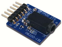
I2S module:
http://store.digilentinc.com/pmod-i2s-stereo-audio-output/
CS4344 datasheet:
http://www.mouser.com/ds/2/76/CS4344-45-48_F2-472818.pdf
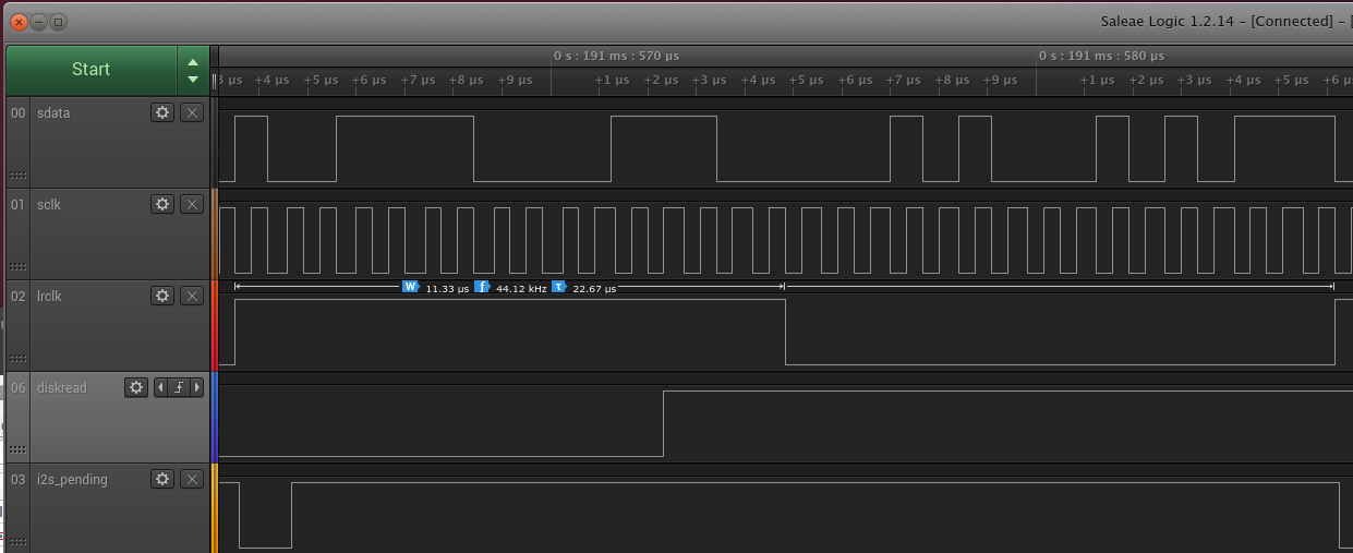
My goal here was for playing CD quality stereo 16 bit x 44.1kHz WAV files from an SD card using the P1V and I now have this functioning and it sounds decent enough with headphones and I don't see problems on the I2S bus with my logic analyser.
To get it to work I mostly just extended the hub.v file.
Firstly I created some new I2S signals and passed these to/from the hub module:
These four signals were also connected through the FPGA internally in top.tdf and dig.v and link up to the external pins assigned to them (the extra plumbing Verilog for that part is not actually shown below, but is simple enough).
For clocking I just used an external oscillator as the source of the 22.5792 MHz master clock but in theory I believe it could also be generated internally using the FPGA PLLs. I determined there are some integer relationships possible to get reduced jitter from a 50MHz source cascaded through two Altera PLLs, but I haven't tried it yet to see if it works.
Then I added a P1V software extension to the existing hub operations with a new method to send samples from a COG to the I2S interface. Audio I2S samples are fed to the I2S interface by a COG simply executing the following instruction (you need PASM as SPIN doesn't support HUBOP directly to my knowledge, even if it could keep up with the rate):
This hub operation instruction causes the COG to stall until its audio sample data is consumed shortly after the rising edge of lrclk, which is a safe time to do so to avoid any setup time metastability across the clock domain. The I2S bus is a shared hub resource and any other COGs also trying to do the same thing while an I2S transfer operation from another COG is still pending are ignored and just return immediately. I could also eventually add in some way to indicate to another COG if the I2S writer is busy and has ignored the request eg, set Carry flag if I2S transfer failed due to being busy, but for now its no big deal if only one COG will access it so I left the behavior as described.
Because hub operation #9 (0_00001001 binary) is also aliased to COGID (xxxxxx001 binary) it is quite safe to use this particular value without modifying the existing COGID operation and it has no side effect on the other hub resources. By default the HUBOP encoding will not write the result so the destination register holding the audio sample data is left as is. If the result bit was ever enabled for the result to be written it would just be the COGID value.
A desirable outcome of the stall is that the rate of data delivery is then accurately locked to the I2S LR clock rate (at 44.1kHz) and it can be used to synchronously pull data from a buffer containing the audio samples (eg. something being filled by reading from an SD card) and play out at the correct rate. This automatic HUBOP execution spacing can also be used to time the audio generation COG objects (such as the great SIDcog/AYcog etc from Ahle2) instead of their typical WAITCNT approaches, assuming they are patched appropriately for operating at the different sample rate. I have had some success there however I don't think SIDcog can run at 44.1kHz sample rate without adding support for a hardware multiply instruction first and then use it to reduce all the volume envelope calculation instructions needed per audio sample. My recollection is that SIDcog wouldn't be able run that fast without such a change. This hardware multiply instruction is of course possible on a P1V and I've successfully used it myself in the past.
An example of how to use it is shown below for AYcog. Original code:
If anyone else wants to play about with I2S on P1V my Verilog additions to hub.v for supporting an I2S output bus are provided below:
Finally lower down I changed the existing bus_ack signal to effectively generate the wait states for the P1V while waiting for the I2S data to be consumed. This was the key to make it work at the right rate. Getting this line correct was a little tricky and for some time it was wrong and I had other COGs being impacted messing up my baud rates etc until I fully understood the pipeline timing and how the bus_sel rotation thing worked.
Now there are possibly simpler ways to implement all this (I'm no Verilog guru) but it works for me and I get CD quality sound output. Over time I might possibly add other features like more programmable clocking/sample rates, support for 24 bit samples and ramps back down to a zero value if I2S has become idle for some time but for now it seems to be working ok and I'm happy enough with it.
Enjoy,
Roger.
I2S module:
http://store.digilentinc.com/pmod-i2s-stereo-audio-output/
CS4344 datasheet:
http://www.mouser.com/ds/2/76/CS4344-45-48_F2-472818.pdf
My goal here was for playing CD quality stereo 16 bit x 44.1kHz WAV files from an SD card using the P1V and I now have this functioning and it sounds decent enough with headphones and I don't see problems on the I2S bus with my logic analyser.
To get it to work I mostly just extended the hub.v file.
Firstly I created some new I2S signals and passed these to/from the hub module:
input 				mclk,    // 22.5792 MHz master input/output clock
output				lrclk,   // I2S LRCLK
output reg			sdata,   // I2S DATA
output 				sclk     // I2S CLOCK
These four signals were also connected through the FPGA internally in top.tdf and dig.v and link up to the external pins assigned to them (the extra plumbing Verilog for that part is not actually shown below, but is simple enough).
For clocking I just used an external oscillator as the source of the 22.5792 MHz master clock but in theory I believe it could also be generated internally using the FPGA PLLs. I determined there are some integer relationships possible to get reduced jitter from a 50MHz source cascaded through two Altera PLLs, but I haven't tried it yet to see if it works.
Then I added a P1V software extension to the existing hub operations with a new method to send samples from a COG to the I2S interface. Audio I2S samples are fed to the I2S interface by a COG simply executing the following instruction (you need PASM as SPIN doesn't support HUBOP directly to my knowledge, even if it could keep up with the rate):
HUBOP audio_sample, #9 ' where the 32 bit audio_sample COG register holds the combined left and right 16 bit signed audio samples
This hub operation instruction causes the COG to stall until its audio sample data is consumed shortly after the rising edge of lrclk, which is a safe time to do so to avoid any setup time metastability across the clock domain. The I2S bus is a shared hub resource and any other COGs also trying to do the same thing while an I2S transfer operation from another COG is still pending are ignored and just return immediately. I could also eventually add in some way to indicate to another COG if the I2S writer is busy and has ignored the request eg, set Carry flag if I2S transfer failed due to being busy, but for now its no big deal if only one COG will access it so I left the behavior as described.
Because hub operation #9 (0_00001001 binary) is also aliased to COGID (xxxxxx001 binary) it is quite safe to use this particular value without modifying the existing COGID operation and it has no side effect on the other hub resources. By default the HUBOP encoding will not write the result so the destination register holding the audio sample data is left as is. If the result bit was ever enabled for the result to be written it would just be the COGID value.
A desirable outcome of the stall is that the rate of data delivery is then accurately locked to the I2S LR clock rate (at 44.1kHz) and it can be used to synchronously pull data from a buffer containing the audio samples (eg. something being filled by reading from an SD card) and play out at the correct rate. This automatic HUBOP execution spacing can also be used to time the audio generation COG objects (such as the great SIDcog/AYcog etc from Ahle2) instead of their typical WAITCNT approaches, assuming they are patched appropriately for operating at the different sample rate. I have had some success there however I don't think SIDcog can run at 44.1kHz sample rate without adding support for a hardware multiply instruction first and then use it to reduce all the volume envelope calculation instructions needed per audio sample. My recollection is that SIDcog wouldn't be able run that fast without such a change. This hardware multiply instruction is of course possible on a P1V and I've successfully used it myself in the past.
An example of how to use it is shown below for AYcog. Original code:
mixer         mov      r1, val31bit                        '  DC offset
              add      r1, out1
              add      r1, out2
              add      r1, out3
              waitcnt  waitCounter, sampleRate             '  Wait until the right time to update
              mov      FRQA, r1                            '  the PWM values in FRQA/FRQB
              mov      FRQB, r1                            '
Code changes needed to use I2S output (creating and passing in signed 16 bit left and right samples, just mono in this case)
mixer         mov      r1, out1
              add      r1, out2
              add      r1, out3
              shr      r1, #16            ' create right sample
              mov      temp, r1           ' save it
              shl      r1, #16            ' create left sample
              or       r1, temp           ' combine them
              hubop    r1, #9             '  Send L&R sample pair to I2S
If anyone else wants to play about with I2S on P1V my Verilog additions to hub.v for supporting an I2S output bus are provided below:
// i2s cog domain stuff is clocked by clk_cog

// an i2s write request (HUBOP sample,#9)
wire i2s = ec && &sc && ac[8:0] == 9'b000001001;

// this register tracks source of pending i2s request
reg [7:0] i2s_req;

always @(posedge clk_cog or negedge nres)
if (!nres)
	i2s_req <= 8'b0;
else if (ena_bus && i2s && ~|i2s_req) // new requests while idle latch bus_sel to track the cog source of i2s request
	i2s_req <= bus_sel;
else if (ena_bus && i2s && |i2s_req && (bus_sel == i2s_req) && !i2s_pending) // clear request once data is written
	i2s_req <= 8'b0;

// flop is true while waiting for data to be consumed
reg i2s_pending;

always @(posedge clk_cog or negedge nres)
if (!nres)
	i2s_pending <= 1'b0;
else if (ena_bus && i2s && ~|i2s_req) // new requests also set pending flag
	i2s_pending <= 1'b1;
else if (ena_bus && !lrclk_cog[2] && lrclk_cog[1]) // rising edge of (delayed) lrclk clears the flag
	i2s_pending <= 1'b0;

// holding buffer
reg [31:0] i2s_data;

always @(posedge clk_cog or negedge nres)
if (!nres)
	i2s_data <= 32'b0;
else if (ena_bus && i2s && |i2s_req && (bus_sel == i2s_req) && !i2s_pending)
	i2s_data <= dc; // latch the data sample at at a safe time

// lrclk is resampled to synchronize over the two clock domains and to avoid metastability
reg [2:0] lrclk_cog;

always @(posedge clk_cog or negedge nres)
if (!nres)
	lrclk_cog <= 3'b0;
else if (ena_bus)
	lrclk_cog <= {lrclk_cog[1:0], lrclk}; // shift in the resampled lrclk signal


// i2s audio domain stuff is clocked by mclk

reg [8:0] sclk_count;

always @(posedge mclk or negedge nres)
if (!nres)
	sclk_count <= 9'b0;
else
	sclk_count <= sclk_count+1;

assign sclk = sclk_count[3];  // mclk divided by 16
assign lrclk = sclk_count[8]; // mclk divided by 512

reg [31:0] i2s_sample;

always @(posedge mclk or negedge nres)
if (!nres)
	i2s_sample <= 32'b0;
else
	if (&sclk_count[8:0])
		i2s_sample <= i2s_data;

always @(posedge mclk or negedge nres)
if (!nres)
	sdata <= 1'b0;
else if (&sclk_count[3:0])
	sdata <= i2s_sample[(sclk_count[8] ? 15 : 31 ) - sclk_count[7:4]];
Finally lower down I changed the existing bus_ack signal to effectively generate the wait states for the P1V while waiting for the I2S data to be consumed. This was the key to make it work at the right rate. Getting this line correct was a little tricky and for some time it was wrong and I had other COGs being impacted messing up my baud rates etc until I fully understood the pipeline timing and how the bus_sel rotation thing worked.
//assign bus_ack		= ed ? {bus_sel[1:0], bus_sel[7:2]} : 8'b0; // original code
assign bus_ack		= ed ? {bus_sel[1:0] & ~{i2s_req[0], i2s_req[7]}, bus_sel[7:2] & ~i2s_req[6:1]} : 8'b0; // new update for I2S
Now there are possibly simpler ways to implement all this (I'm no Verilog guru) but it works for me and I get CD quality sound output. Over time I might possibly add other features like more programmable clocking/sample rates, support for 24 bit samples and ramps back down to a zero value if I2S has become idle for some time but for now it seems to be working ok and I'm happy enough with it.
Enjoy,
Roger.
Comments
Very cool.
Are you able to also test this on a P2 platform, using the Smart Pin cells ?
In theory, i2s should be easy to craft via P2 pin cells, but the details can matter..... I'm not sure how the NCOs play here ?
It would be possible to add that hubop into my faster spin if you really wanted it. I have a ROM version of the faster spin for the P1V.
BTW I have been thinking of getting back into P1V to increase hub ram beyond 64KB using one of the larger cyclone boards supported for the P2.
One of the things with P1V that would be good to do is speed up the hub access to 1:8 (ie single clock instead of the current 2 clock per cog window). This would permit either 2x hub speedup or 16 cogs with 1:16.
The other P1V nicety would be to see if we could increase base clock frequency. However, I don't understand Quartus enough to use the timing to verify, and currently IIRC there are reported timing errors currently.
Ray
@jmg, haven't played with P2, staying out of that lot for now.
@Cluso99, yeah adding more hub RAM to the P1V is pretty satisfying and opens up more possibilities. I had the earlier SDRAM and SRAM projects and they both allow more applications, especially with XMM & PropGCC and using it for larger programs, graphics etc. I've not played with increasing hub speeds or adding more COGs, though I'd admit there is probably scope there, I just haven't really had the need yet. Now that I have this decent quality I2S audio and once I put the external RAM support back in, I would also one day like to mess around with some wavetable stuff and mod files etc. But I have plenty of things to play about with right now...
As to supporting hubop I2S transfers directly in spin, I was wondering if it would be helpful or not compared to PASM. Perhaps with a very tight spin loop you would be just able to use it, but it may not be able to do a whole lot more work or samples would begin to get skipped at 44.1kHz and the audio will be stretched. Maybe a player loop would just fit with included some data access operations and double buffer wraparound tests and song complete tests etc. But I'd be suprised it could reliably do much more than that without adding jitter to the output which is noticeable. Certainly no time to wait to read data off disk while in this loop. You'd need another COG anyway.
On a regular P1 it would be great to be able to incorporate an I2S bus in player loops like AYcog etc without using an additional PASM COG dedicated for outputting the I2S data like I had tested originally.
For a 32 bit I2S sample (16 bit left and 16 bit right) it is easy enough to get the video generator output 32 bits with a frame rate very close to 44.1kHz and stream out all the 32 bits for you in one go, and I've already had that working. The MCLK signal can also be driven by the counter feeding the PLL. What's nice on this particular PMOD module the SCLK can be derived internally by the CS4344 chip so that output signal can be held fixed and there is no need to generate it, so that solves that problem too. However there still needs to be the LRCLK generated which is also out of phase by one bit from the overall WAITVID output data frame. I wonder if there is some way that two counters could be used, CTRA for doing the WAITVID and the CTRB to generate an LRCLK at a rate that is 1/32 of the WAITVID's data rate. The key there is to get the two counters in PLL mode and their phase offsets aligned by one I2S data bit and then remain locked. I'm not sure if the two COG counters PLL outputs can be reliably initialized like that, but if so it might be worth a try. The CS4344 might tolerate some amount of phase inaccuracy there too (if less than a data bit), but again not sure. Actually if the two PLLs can be locked to any fixed bit, data can always be rotated to compensate for the skew. Key is that this skew is known and remains fixed. Maybe it could be measured by the COG at boot time if it is random each time.
So if this general concept above was achievable on a regular Propeller you could just patch AYcog etc to use a WAITVID instruction instead of my HUPOB #9 instruction in the modified example above. It would lock the output to the 44.1kHz nicely and save a COG.
mixer         mov      r1, out1
              add      r1, out2
              add      r1, out3
              shr      r1, #16            ' create right sample
              mov      temp, r1           ' save it
              shl      r1, #16            ' create left sample
              or       r1, temp           ' combine them
              waitvid  clkpinmask, r1     '  Send L&R sample pair to I2S
If you can't initialise the two counters as I hoped above, you can still do I2S in a single COG with a single counter by using the WAITVID sending 16 bit frames (in two color mode) and send L&R samples separately using one WAITVID instruction for each. One WAITVID "color" is chosen to drive the LRCLK pin high, the other drives LRCLK low and in fact this is how I did my initial I2S module test. You do need to rotate the audio sample data by one bit too. The only downside with that approach is that you have to split your sample generation code into two hopefully equal pieces, so the two WAITVIDs can be issued in time every 11.34us. It is however obviously nicer to have it handled with a single WAITVID as that lets you use most of the 22.68us interval to do other useful work without stopping halfway to send out a signal audio channel's sample.
A natural extension of this would be a CtrCLR pair too.
With those, you could preload/configure, then enable last, and ensure they started in sync on the same and atomic clock edge.
I think it would be better to use CTRB in NCO mode. You can set an initial phase and start it deterministically, like right after a waitvid. It would be similar to the USB receiver. Maybe write PHSB after every waitvid to prevent an offset from accumulating.
I'm guessing the LRCLK is a steering signal, and it can tolerate some jitter, so this aperture effect might be OK.
Where LRCLK is used to synth a SCLK it may be less tolerant, and the write PHSB after every waitvid may help
I get, for one example of MCLK
80M*round(2^32*11.2896M/80M)/2^32 = 11289600 that one is exact
80M*round(2^32*44.1k/80M)/2^32 = 44100.00518 that one is not quite exact
but maybe this is better ?
80M*256*round(2^32*44.1k/80M)/2^32 = 11289601.33 0.1ppm error, but now they are phase locked
Did you check that with a NCO LRCLK to lock this internally SCLK ?
Data I see says "12. In Internal SCLK Mode, the Duty Cycle must be 50% +/- 1/2 MCLK Period.", so 80MHz level jitters look to be OK.
If/when I get around to it I'd like to try a real P1 again with a single WAITVID implementation to see if it is doable and can be integrated into SIDcog/AYCog etc. Not sure when that will be as I'm mainly engrossed in P1V right now. Its probably possible to patch SIDcog with I2S and just keep its sample rate at 30789Hz or whatever it is and just clock the I2S device at that rate too. That way you don't need to modify the SIDcog code much at all to get the benefit of I2S audio.
Even if LRCLK is fed to a PLL it shouldn't be any worse than using the Propeller PLL. The Propeller PLLs don't filter much jitter anyway. I don't know if there would be data transfer issues if the DAC PLL filters jitter and the Propeller doesn't. I don't think multiplying LRCLK up to SCLK or MCLK makes sense if it's only 44kHz. Do any parts do this?
crystal for the Prop, running at 98.304MHz system clock which is exactly 2048 clocks per sample
at 48kSPS (one of the standard I2S frequencies). That typically gives 8 instructions per BCLK which
makes it easy to drive both an ADC and a DAC simultaneously in one cog IIRC, and the MCLK is jitter-free
being 1/8th of the system clock typically.
So I couldn't help myself and dug out my ProtoBoard and was able to get the LRCLOCK generated in software and use WAITVID to output both 16 bit samples in a single go. Audio is working and it sounds okay for now.
Hacked up PASM test code is shown below. Forgive my hardcoding.
pin8 = SDATA (from WAITVID)
pin9 = SCLK (fixed high, generates internal SCLK inside DAC)
pin10 = LRCLK (counter B NCO)
pin11 = MCLK (counter A PLL)
This code results in continously reading a stereo sample from the PAR register address and outputting using a 32 bit WAITVID with an LRCLK transition half way in the 22.68us loop. I think I may still need to invert the LRCLK pulse if the left sample comes first, need to confirm. The two NOPs after the waitvid seemed to help align the edge very close to the bit transition.
In this screenshot from my scope you can see the effective jitter (yellow trace is the synthesized LR clock using counter B in NCO mode, blue is the MCLK output from PLL mode counter A that feeds the video generator, scope triggered on LRCLK edge). I had persistence on for a while and it seems to be showing only a small amount of jitter maybe within +/- 12.5ns and certainly less than 1/2 MCLK that the spec for the CS4344 mentioned. Sound quality doesn't seem to suffer from this on this DAC (at least to my non-golden ears).
One thing I found I had to do in the PASM code was save the last bit of the last sample and rotate it into the next sample to account for the I2S format. Also reversing the bits in the sample to deal with WAITVID sending the LSB first instead of MSB I2S expects. But they were simple things to put in.
I'm still playing around with it and want to try to incorporate this into the SIDCog itself to see how nicely it plays (at a lower sample rate than 44.1kHz though). Should work ok.
I did not think that would be necessary. I was thinking that ctrb could free-run at the correct frequency, or nearly correct as calculated by @jmg. The LRCLK transition would happen before the last bit of the word is sent, probably before the waitvid. So instead of rotating the data we shift the clock. It could probably be done using ctrb in PLL mode*, but it's easy in NCO mode. If the counters are running at exact harmonics the phsb write should only be needed once after the first waitvid to adjust the phase of ctrb to match the video generator. Please forgive me if you tried this and it didn't work.
*Nevermind. The recommended minimum pll frequency is 500kHz.
Haven't tried out your suggestions but it could be good to save a few more instructions if it works.
Today I was able to modify the SIDCog audio generator object to output I2S audio itself to eliminate an additional COG otherwise required for doing this. If anyone wants to play with I2S, here is a patched version of v1.3 (I called it v1.3b) that supports the CS4344 I2S DAC (tested at 80MHz) instead of its original RC filtered DUTY cycle output. It relies on the CS4344 to generate the SCLK internally and the Propeller just holds this SCLK signal high to disable its DE-EMPHASIS mode. Counter PLL A generates MCLK, and clocks the WAITVIDs. Counter B is used in NCO mode to generate and align the LRCLK edges after WAITVID.
Here's the updated SIDCog. Annoyingly I couldn't get the _CLKFREQ to work in my constant calculations (with BST) and so I created another PROP_FREQ constant that can be patched if ever different to 80MHz.
Enjoy,
Roger.
Many thanks SIDi2s working great.
Is possible make same AYcog modification and make obex i2s driver for general use ? (like sine wave gen and other)
Many many thanks
Kamil
Glad to hear it works for you @JLS.
Yes it should be possible to change the AYCog in a similar way, however the sample rate for that object is set higher at 125kHz so there would be some other changes required. I haven't tried but you could give it a go if you have your i2s already working. I think you'll probably want to run it at 88.2kHz and probably scale some of these audio parameters below down according to the new rate to keep it in tune. Maybe your i2s module can even be operated at 125kHz, not sure. But for that rate the mclk would probably then need to be either 8 or 16MHz. Perhaps the P1 can be coaxed to generate a nice 8MHz. The other timing information I use for the P1 PLLA would need to be scaled too for a LR clock rate different to 44.1kHz or the one I'd computed for SIDCogI2s. Have a play around and give it a go and see what you get out of it.
As to OBEX I2S drivers yeah I sort of hoped I might add that when I get a chance (or someone else knowledgable may do so in the meantime based on this thread information). I am deep into P1V Verilog right now for some other video stuff and so don't want to stop, but if there's a break I might.
Cheers,
Roger.
ps. by the way, an I2S object can be constructed to read its stereo sample from a single long address that is written to by another COG for the sample. Like SIDcog already does at register offset 28. It would take another COG for the I2S output, but it is then generic and works with any sample rate being written into the sample address in memory by the generator object. It then outputs at its own sample rate and I guess it behaves like a rudimentary sample rate converter (no interpolation). I've used this approach before with I2S and SPDIF objects. YMMV with the sound quality by doing this but it sounded okay enough to me for general purpose use. You can also use this approach to scale/mix from various source objects that output into different hub addresses at different rates.
Here's the patched AYCog spin object code with the mod required for digital audio via a CS4344 I2S DAC (I called it v0.8b). You can change the SAMPLE_RATE parameter and it will adjust the required PLL rate accordingly and it should also remain in tune too. I tried a range of sample rates from 10kHz up to 100kHz which worked, but I have just set the default sample rate to run at 88200Hz (2xCD). The original value was 125kHz.
It is currently coded for 80MHz Propellers but that should be adjustable too with the PROP_FREQ parameter, however I didn't try any other speeds than 80MHz so YMMV.
Roger.
New AYi2s is working.
Next step is SNEcog ? :-D
Thanks your work
https://hackaday.io/project/24911
===Jac
Roger.
Many thanks SIDcogi2s, AYcogi2s and SNEcogi2s all working fine.
Is possible make Retronitus, PM_synth i2s mod ?
Propeller is my dream platform :-)
Many thanks
Kamil