

Color LCD Driver for cheap 1.44" SPI 128*128 V1.1 (Red and Black PCBs)
 Cluso99
Posts: 18,071
Cluso99
Posts: 18,071
Update 15thOctober 2016
This link is to v0.55 which is much faster and uses a separate PASM Cog for the low level access.
forums.parallax.com/discussion/comment/1390134/#Comment_1390134
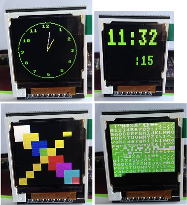
Attached is a demo program in SPIN for drawing text, lines, boxes and circles.
Samples for a round clock and a digital clock are also shown (not accurate and no adjustment method) just for proof of concept.
I have added delays in the LCD driver which may or may not be required.
The demo program runs samples of each type, ending in the digital clock. This can be used as a driver for the LCD.
You will need to change the "lcdInit" call to select either the red pcb or black pcb version as they are different.
These LCDs can be had for ~$4 on eBay. The LCD is known as 1.44' SPI 128*128 V1.1 and comes in red pcb and black pcb versions. The ILI9163 is the IC used (or compatible).
The LCD is often referred to as a Nokia 5110 color replacement but the similarity is only regarding the SPI interface, not the register set!

ILI9163_spi_040(1).zip
This link is to v0.55 which is much faster and uses a separate PASM Cog for the low level access.
forums.parallax.com/discussion/comment/1390134/#Comment_1390134
Attached is a demo program in SPIN for drawing text, lines, boxes and circles.
Samples for a round clock and a digital clock are also shown (not accurate and no adjustment method) just for proof of concept.
I have added delays in the LCD driver which may or may not be required.
The demo program runs samples of each type, ending in the digital clock. This can be used as a driver for the LCD.
You will need to change the "lcdInit" call to select either the red pcb or black pcb version as they are different.
These LCDs can be had for ~$4 on eBay. The LCD is known as 1.44' SPI 128*128 V1.1 and comes in red pcb and black pcb versions. The ILI9163 is the IC used (or compatible).
The LCD is often referred to as a Nokia 5110 color replacement but the similarity is only regarding the SPI interface, not the register set!
ILI9163_spi_040(1).zip
Comments
These little colour displays are getting so cheap nowadays. Is this the one? http://www.ebay.com.au/itm/1-44-Serial-LCD-Display-128-128-SPI-TFT-Color-Screen-With-PCB-Adapter-5110-New-/181370175893?pt=LH_DefaultDomain_15&hash=item2a3a814195
I bought my black ones here
http://www.ebay.com.au/itm/141239781210?ssPageName=STRK:MEWNX:IT&_trksid=p3984.m1439.l2649
I see both Black and Red are available with free shipping to the US.
Is there any advantages with one or the other?
Jim
Both are fine. The black doesn't require an offset. Red to black is rotated 180 degrees, but each can be rotated in software, so no diff here.
I can get the black cheaper than the red here.
I think I may go with:
http://www.ebay.com/itm/5Pcs1-44-Red-Serial-128X128-SPI-Color-TFT-LCD-Module-Replace-Nokia-5110-LCD-/321508312465
The 6yr old has had fun watching me write the code to make the LCD display boxes, then lines, then circles. He hasn't seen the clockface yet.
We are just trying to pique their interest in electronics and programming.
Now it's time for me to make a pcb. I plan on my usual 1"sq pcbs with a prop, eprom, xtal, 2 pb switches, 3v3 reg and microUSB socket for 5V input. It will be SMT.
It will really be a dedicated pcb for this LCD, so I will only be making a few via OSHPark. If any of you want a pcb (assembled or not) let me know. Remember I am in Oz so postage from here is ~$2.80 + ~$0.50 for padded bag.
I have a few 18650 3v7 rechargables and Power Pack (microUSB for charging and USB for 5V out) which are targeted to charge mobile phones for powering these.
http://www.ebay.com.au/itm/321453091428?var=510349015182&ssPageName=STRK:MEWNX:IT&_trksid=p3984.m1439.l2649
http://www.ebay.com.au/itm/381091833604?ssPageName=STRK:MEWNX:IT&_trksid=p3984.m1439.l2649
BTW I haven't tried these yet to determine the uptime.
When I finally get my 3D printer working I can make a case (no hurry here - its been over 2 yrs in the making).
If I read the ILI9163 specs correctly, this chip (drives the LCD) only caters for up to 160*160 dots. The larger screens use different chips for more pixels, and therefore require different drivers.
Are there any 160*160 displays that match the Chip's ability ?
I found this (but not 0.1" pins)
1.8" Serial TFT Color LCD Display Module With SPI Interface 128X160 AU $1.89
http://www.ebay.com.au/itm/1-8-Serial-TFT-Color-LCD-Display-Module-With-SPI-Interface-128X160-5-IO-Ports-/190975337816?pt=AU_B_I_Electrical_Test_Equipment&hash=item2c77046558
addit
This one has pins (" PCB Adapter Power IC SD Socket") AU $2.79
http://www.ebay.com.au/itm/1-8-Serial-LCD-Display-SPI-TFT-Module-PCB-Adapter-Power-IC-SD-Socket-128X160-/190920594011?pt=AU_B_I_Electrical_Test_Equipment&hash=item2c73c1125b
If you look at my pics in the first post, the digits in the digital clock are from an 8x8 font that I rendered as (IIRC here) as 3*8 wide and 6*8 high. My routines permit any multiple of 8*8 font.
Or, you can create you own much nicer larger fonts. Mine are more blocky.
sorry, that I am digging out this old thread.
I'm just curious whether you have continued developing the driver for this type of color lcds.
Do you maybe have a PASM version?
If so, could you please publish it?
Greetings
Patrick
thanks for your reply.
So, you haven't made any changes on the driver since January 2015?
I have some ideas for improvements, which I will most likely try to implement:
- PASM low level driver for more speed while updating the screen
- Using the Propeller internal fonts for character generation
- etc.
160x120 1.8" full color(ignore what it says on the board:), works perfectly well with Cluso's driver... except for the digital clock. I adjusted the width and height to get full screen. Other than that, works fine, can see it perfectly in sun lit room. BUT very, very slow. I'm hoping Patrick1ab works a little magic, I'd really like to see this board as a viable option for my PropPhone.
I have found the monochromatic uOLED displays with pasm SPI by Thomas Sullivan (found in the Hackable Badge) to work very well and be very bright. https://parallax.com/product/20200
(default is compiled for my P8XBlade2 12MHz*8 and P0..7 = VCC...LED, black LCD board)
BTW AliExpress has these for US$2.70 incl postage now.
Now powered from the prop pins P0=VCC, P1=GND, P7=LED
It's slow because it is only written in spin.
Implements a PASM Cog SPI driver. It's faster, but all other code is still in SPIN.
The clock now has hours, minutes & seconds hands, but I have not fully checked the clock hands repaint correctly.
Much faster!!! Uses separate cog to run low level PASM code.
Normal 8*8 font is within the pasm cog and writing characters to the screen is quite fast. Drawing boxes is almost instantaneous.
I haven't placed the code in it's own callable object (yet anyway). I didn't start out that way.
You will need to recompile for 5MHz PLL16.
Enjoy
Cluso, on behalf of all interested users, thank you very much for sharing your excellent development work on this economical and powerful display device.
Here is v1.00 of the LCD Spin/Pasm Object and v0.61 Demo to drive the object.
The round analog clock hopefully works properly, incrementing the hour hand every 12 minutes, and complete with a second hand.
Please remember to recompile for 5MHz PLL16.
Enjoy
Note: Peter also has this LCD running on Tachyon
forums.parallax.com/discussion/comment/1390619/#Comment_1390619
Almost working with latest displays (v2.1)...
The version of the LCD boards I bought on eBay are 144' SPU 128*128 V2.1 (http://www.ebay.com/itm/251494743565?_trksid=p2060353.m2749.l2649&ssPageName=STRK%3AMEBIDX%3AIT)... They appear to use a 'ST7735S' TFT LCD driver chip (claimed: "Compatible 5110 interface"). So, that could be a cause of these problems. But, it's interesting that your early version of the driver 'almost' works.
BTW: I tried with 10K pull-ups on SDA & SCK and without pull-ups as well.
With your earlier driver, ILI9163_spi_040.spin I get 'some' portion of the demo working on ¾ of the LCD screen. The program 'clears' the full screen to random pixels, then draws the alpha characters over ¾ of the screen, leaving a rectangle of random pixels. Then, as the demo clears the alpha characters and progresses, the color squares are drawn and appear to draw a bit over the random pixels. Further demo parts draw only on ¾ of the LCD screens (clocks, lines, etc...)
With Demo_ILI9163_spi_061.spin & LCD_ILI9163_SPI_v100.spin, Only the backlight is lit and will occasionally flash as the program tries to clear the screen and draw.
I have not looked up this driver chip yet, so it could be quite different than the ILI9163.
dgately
I haven't checked the ST7735S chip.
BTW the 5110 reference is bogus. Its nothing like the 5110 LCD. I have a thread and driver for the 5110 but its mono.
LCD Driver now
1. Supports both 6*8 and 8*8 fonts
2. Both fonts are loaded into the assembly cog, permitting reuse of hub ram once the pasm cog starts
3. Supported fonts for characters $20..$7F. Control characters $00..$1F are converted to $7F
Demo program includes both font examples, plus analog style clock. Time and Date are also shown in digital.
The Date does not increment and is left as an exercise for the user, as is setting/adjusting the Time. I have checked it is accurate for a couple of days.
BTW the LCD is much sharper than my pic shows. It's not blurred at all!
1) The ILI9163's Vcc range is 2.6 V to 3.3 V, so powering at the 3.3V is generally a bad idea. The board I have has a 3.0 V LDO on it so I have to run it from 5 V, however there is a solder jumper site to bypass the regulator so it could be powered directly. But I would still stay away from a nominal 3.3 V supply. (On the other hand the data sheet allows up to 4.6 V in section 17.1 under absolute maximum ratings so likely no damage would ensue.)
2) Powering and especially grounding of the display using Prop pins is a really bad idea. On the ground side, this violates many good practices. There are two big concerns here:
2a) all the current surges and spikes that the display may (nay, will) produce will be conducted through the Prop. This could cause many surprising, intermittent and therefore difficult to track down problems in other parts of the system;
2b) The ILI9163's data sheet does not admit to the chip taking any current but the Prop's DC characteristics are such that 10 mA is a good limit to observe, and my gut feel is that these displays could take more than that...I'll try to remember to measure this aspect when I get my module up and running (I just dusted off the display purchased last year).
Now it may be that the inherent drop at the Prop's pins due to point 2b) is actually mitigating the concern of point 1), but this opens up even more potential interfacing issues due to the possibility of logic signals coming in to the driver chip at voltages lower than its local ground.
Anyway thanks, Cluso99 for the great work writing the driver: I expect it will work great once I connect up the display.
(Note the Altoids tin is a 3 V to 5 V boost reg.)