

USB Transmit
 cgracey
Posts: 14,323
cgracey
Posts: 14,323
I got the transmitter working. It does everything but the CRC computation.
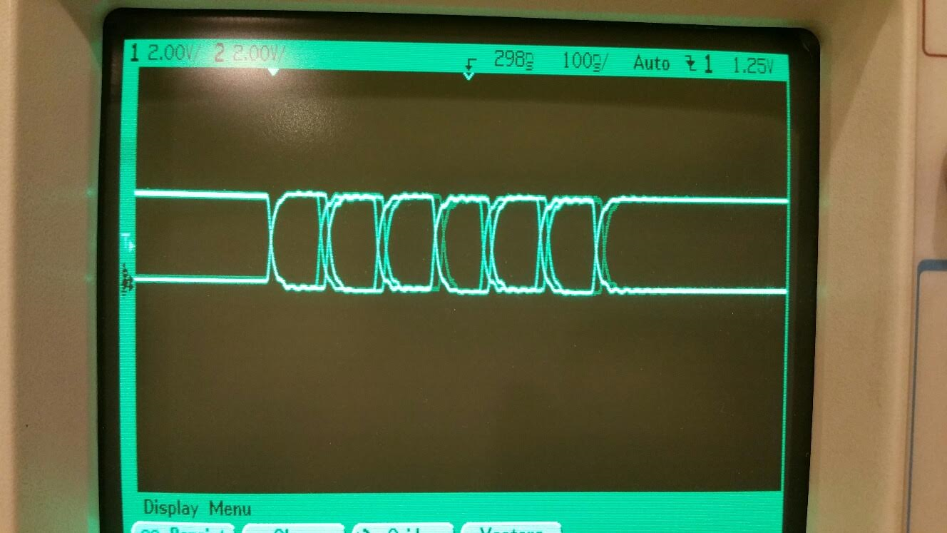
Here is a picture of the waveform from sending the sync byte ($80), followed by an $FF byte, which forces bit-stuffing. When the transmitter sees that there are no more bytes, it automatically sends an EOP (end of packet, or SE0+SE0+J+IDLE). There are exactly three bits per division on the scope:

Here is a close-up of the jitter in the sync pattern at 80MHz clocking:
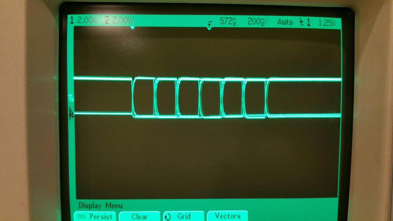
Here is what it will look like at 160MHz clocking. I just cut the baud in half so you can get an idea of the relative jitter:
Here's the program that did it. I don't have any handshaking via IN working yet, but you can get the idea:
Here is a picture of the waveform from sending the sync byte ($80), followed by an $FF byte, which forces bit-stuffing. When the transmitter sees that there are no more bytes, it automatically sends an EOP (end of packet, or SE0+SE0+J+IDLE). There are exactly three bits per division on the scope:
Here is a close-up of the jitter in the sync pattern at 80MHz clocking:
Here is what it will look like at 160MHz clocking. I just cut the baud in half so you can get an idea of the relative jitter:
Here's the program that did it. I don't have any handshaking via IN working yet, but you can get the idea:
dat		org

		pinsetm	pm_usb,	#1	'configure usb DP pin (passive)

		pinsetm	pm_usb,	#0	'configure usb DM pin (the brain)
		pinsetx	baud,	#0	'configure usb 12Mbps

		mov	dira,#%11	'enable smart pins 1..0

.loop		pinsety	#$180,#0	'send 1st byte (msb must be set)
		pinsety	#$FF,#0		'send 2nd byte (may send any number of bytes)
		waitx	##1000		'after bytes run out, smart pin sends EOP
		jmp	#.loop


pm_usb		long	%1_11011_1	'usb device, full speed, output enable 'on'
baud		long	$2666
Comments
So, I guess the basic idea is that we create a data packet, calculate the 16-bit CRC and then send it to the smartpins?
I'm sure there are a lot of other things that need to be sent first before sending the data packets.
(Reading Wikipedia).
As I recall, it faked receiving and really only transmitted properly...
Using your example, how do we send a block of bytes? I mean, how do we wait for the smart pins buffer register to be empty so we can send the next byte without an underrun causing EOP to be sent? (Sorry I have not been following the smart pins usage closely)
Time to dig out my FPGA boards...
There is an interesting effect, just visible in that scope image.
80MHz -> 12MHz should ideally be /7/7/6, which means every 3rd edge should be jitter free.
That is nearly the case, as the jitter on edge 3 is much fainter, but I think this is a NCO rounding effect.
Can also be configured to work at LS USB speeds too ?
Good job.
I'll add the buffer-full feedback tonight, so sustained byte streams can be sent out.
The USB spec states you can turn the bus around from 2 to 6.5 bit periods (or 7.5, depending on the cable):
Yeah, this did get to be fun when I finally realized WHAT to do.
I find
For low-speed communications, the data rate is specified to be 1.5 Mbps +/- 1.5%. For full-speed communications, the data rate is specified to be 12 Mbps +/- 0.25%.
I think for low speed, you just flip the idle polarity & pullup side, and there was maybe some other timing fine-point I cannot find again now....
With 14b NCO, I get choices of 12.00195312 MHz or 11.99707031MHz +162ppm and -244ppm
For Full Speed, Hosting, MCUs often lock onto the USB frame of 1ms, so it would be nice if that 1ms was reasonably jitter free.
If they use that for timing, it should have no long term drifts.
I think if the NCO can be reset, user code just needs to use 80M/80000 and reset the NCO to get jitter-free 1ms ?
The USB smart pin handles all the polarity issues, including pin-variable 1.5k pull-up for devices and 15k pull-downs for hosts.
Thanks for the baud accuracy requirements. Looks like we are good there.
The last frontier in hardware would be CRC generation. Any idea how that works? I learned this once, but it's gone now.
http://www.ti.com/lit/an/spraat5a/spraat5a.pdf
The two CRCs are discussed in the 8.3.5 of the USB 2 spec and scattered throughout in other places, but there are some more useful details here:
http://www.usb.org/developers/docs/whitepapers/crcdes.pdf
There is a brief HW implementation of someone's USB CRC implementation described here (not sure it is correct or not).
http://www.oguchi-rd.com/technology/crc5.pdf
http://www.oguchi-rd.com/technology/crc16.pdf
As you can see by the examples above in general what is required for CRC is a shift register (which you may already have for stuffing etc) and a few XOR gates. There are likely some other important details to get right with respect to initial seeds, bit endianness and complementing at the end or not etc.
If you are going to be adding CRC into HW you will certainly want to verify against known values to be sure you have it right. So a capture and decode of the USB bus at your transmitter's output would be handy. If you ultimately go with the SW LUT approach discussed previously using stack RAM for the CRC table it will be possible to get it right regardless.
The first document is useful if you have a known sequence of data you can check your HW against vs SW computation.
I still haven't figured USB out yet, but looks like the data packets (presumably the highest speed part) wants CRC-16 while some weird packets want CRC-5.
I suppose that, since we're now talking about full speed USB, that CRC-16 in the smart pin would be very useful.
I think for now, yes.
Yes, small control packets use the smaller CRC
There is a turn-around time that may steer where CRC is finally done, ie if you want to receive, and then quickly ACK/NACK , but for first testing, a SW CRC would be ok.
CRC-16 has 2 useful versions (different feedback taps). There are also further variants that preset the start value, and also invert the result. As long as we can preload, then all will be fine.
BTW we can always use a 256 (byte/word?) lookup table.
This morning I have been looking for what I have done previously. I found a CRC directory so I can probably repost a spin program that calculates CRC16. (I've coded CRC16 (IBM) in MC6800 micros more than 30 years ago - 1200 baud seems so is[/] ancient and slow!.
Anyway, I will dig it all out again and get back up to speed.
Attached is Altera info for CRC in Verilog/vhdl.
'' ┌──────────────────────────────────────────────────────────────────────────┐ '' │ Calculate CRC.spin v0.0x │ '' ├──────────────────────────────────────────────────────────────────────────┤ '' │ Author: (c) 2013 "Cluso99" (Ray Rodrick) │ '' └──────────────────────────────────────────────────────────────────────────┘ '' RR20131128 This program calculates the CRC16-USB/IBM and CRC5-usb { REPS #2,#8 '\\ ?? 2 instructions, 8 loops NOP '|| 1 delay instr SHR DATA, #1 WC '\\ C:=DATA[0] CRCBIT CRC '// accumulate 1bit into crc } CON _clkmode = xtal1 + pll16x _xinfreq = 5_000_000 '''''''''''6_500_000 '<------- check this ' _xinfreq = 6_500_000 '''''''''''6_500_000 '<------- check this rxPin = 31 'serial txPin = 30 baud = 115200 VAR long CRC long POLY long BITS long DATA OBJ fdx : "FullDuplexSerial" PUB Main | i, b,c,d,x waitcnt(clkfreq*5 + cnt) 'delay (5 secs) to get terminal program runnining (if required) fdx.start(rxPin,txPin,0,baud) 'start serial driver to PC fdx.tx (13) ''''(0) 'cls fdx.str(string("Test CRC16 USB",13)) POLY := $A001 BITS := 16 CRC := $FFFF ' initialise repeat 10 DATA := fdx.rx ' wait for char input fdx.hex(DATA,2) d := DATA & $FF repeat i from 0 to 7 c := (d ^ crc) & $01 ' data bit 0 XOR crc bit 0 d := d >> 1 ' data >> 1 crc := crc >> 1 ' crc >> 1 if c crc := crc ^ poly ' if c==1: crc xor poly fdx.tx(" ") fdx.hex(crc,4) ' invert before sending, then send low byte first x := crc ^ $FFFF fdx.tx(" ") fdx.tx("$") fdx.hex(x,4) fdx.tx(13) POLY := $14 BITS := 5 CRC := $1F ' initialise repeat DATA := fdx.rx ' wait for char input fdx.hex(DATA,2) d := DATA & $FF repeat i from 0 to 7 c := (d ^ crc) & $01 ' data bit 0 XOR crc bit 0 d := d >> 1 ' data >> 1 crc := crc >> 1 ' crc >> 1 if c crc := crc ^ poly ' if c==1: crc xor poly fdx.tx(" ") fdx.hex(crc,4) fdx.tx(13)That was good information on the CRC issue.
My gut feeling is that this should be handled in software. The raw computation is simple enough to do in hardware, but when it comes to placing CRCs into, and/or extracting them from, bit fields within packets, it blossoms into a big mess. It looks to me like it would complicate the heck out of the USB transceiver. In software, though, CRC can be handled in a much tidier fashion, assuming we can quickly add bytes into the CRC computations, hopefully using a lookup table, as someone suggested.
Can anyone confirm that, within a few instructions, we can exploit a lookup table to incorporate a byte into the CRC5 and CRC16 accumulations? If we have that covered, the hardware is going to stay very simple. If we can do this on an incremental, byte-by-byte basis, it will be no problem to tally up, insert, or extract and compare CRC bit fields at the software level.
The CRC16-IBM/USB poly is $A001 with initial $FFFF (x^16 + x^15 + x^2 + 1)
The CRC16-CCITT poly is $8408 with initial $FFFF (x^16 + x^12 + x^5 + 1)
Xmodem uses CRC16-CCITT with a twist due to an implementation bug???
There is FPGA Verilog code for both USB 1.1 TX & RX PHY at
http://opencores.org/project,usb_phy
SW CRC makes good use of available COG resources (ie. stack RAM), I sent out a PASM algorithm in a previous post discussing CRCs which I expect should be readily be able to computed byte by byte using a look up table as the data arrives or is sent out. I'll try to reference that post again in a bit and add it below...from recollection I think it was about 5 or 6 instructions per byte in an existing packet loop which at 12Mbps is less than 2 bit times at 50MIPs and hopefully that is sufficient for data CRC validation and ACK response. Remember we can even start to send the sync out for the ACK/NAK token before we have to know the final CRC result anyway so that buys us a lot more time during turnaround to play with (another byte). Gut feeling that this delay should be safe, but that should be double checked.
More information for a table based approach in an Application note by Microchip which covers the actual LUT values too for the CRC16 algorithm USB uses (same polynomial).
http://ww1.microchip.com/downloads/en/AppNotes/00730a.pdf
I've not looked at the CRC5 directly but that is potentially smaller (no need for 16 bit accumulator shifting) and in the worst case messages can always have precomputed CRCs/tokens to be sent if a similer table implementation wasn't possible, though I'd be very surprised if a LUT approach doesn't work there either. Now that you have 512 bytes of stack RAM in the COG, both CRC16 and CRC5 tables could share it to avoid shifting and masking, and in a single COG USB implementation (if doable) the same CRC table(s) can be shared between Tx generation and Rx checking too as it is always half duplex transmission anyway.
http://forums.parallax.com/discussion/comment/1366504/#Comment_1366504
This www information I found is also good, and will generate the table data for you...
If you know Ruby syntax (I don't) they even provide the algorithm, though it looks portable enough to PASM.
http://www.rubydoc.info/gems/digest-crc/Digest/CRC16
def update(data)
  data.each_byte do |b|
    @crc = ((@table[(@crc ^ b) & 0xff] ^ (@crc >> 8)) & 0xffff)
  end

  return self
end
http://www.rubydoc.info/gems/digest-crc/Digest/CRC5
def update(data) data.each_byte do |b| @crc = ((@table[((@crc >> 3) ^ b) & 0xff] ^ (@crc >> 8)) & @crc_mask) end return self endWe'll have plenty of time to get these CRCs computed and it will take a lot of potential complexity out of the smart pin.
I'm getting the transmitter combed clean and then I'll implement the receiver. This was such a brain buster before I realized those things don't belong together. I think I lost a week.
'PRI updcrc(crc, data) ' return (word[@crctab][(crc >> 8) & $ff] ^ (crc << 8) ^ data) & $ffff updcrc mov t1, crc test t1, #$100 wz shr t1, #9 add t1, #crctab movs :load, t1 shl crc, #8 :load mov t1, 0-0 if_nz shr t1, #16 xor crc, t1 xor crc, rxdata and crc, word_mask updcrc_ret ret ' ' ' Initialized data ' ' word_mask long $ffff crctab word $0000, $1021, $2042, $3063, $4084, $50a5, $60c6, $70e7 word $8108, $9129, $a14a, $b16b, $c18c, $d1ad, $e1ce, $f1ef word $1231, $0210, $3273, $2252, $52b5, $4294, $72f7, $62d6 word $9339, $8318, $b37b, $a35a, $d3bd, $c39c, $f3ff, $e3de word $2462, $3443, $0420, $1401, $64e6, $74c7, $44a4, $5485 word $a56a, $b54b, $8528, $9509, $e5ee, $f5cf, $c5ac, $d58d word $3653, $2672, $1611, $0630, $76d7, $66f6, $5695, $46b4 word $b75b, $a77a, $9719, $8738, $f7df, $e7fe, $d79d, $c7bc word $48c4, $58e5, $6886, $78a7, $0840, $1861, $2802, $3823 word $c9cc, $d9ed, $e98e, $f9af, $8948, $9969, $a90a, $b92b word $5af5, $4ad4, $7ab7, $6a96, $1a71, $0a50, $3a33, $2a12 word $dbfd, $cbdc, $fbbf, $eb9e, $9b79, $8b58, $bb3b, $ab1a word $6ca6, $7c87, $4ce4, $5cc5, $2c22, $3c03, $0c60, $1c41 word $edae, $fd8f, $cdec, $ddcd, $ad2a, $bd0b, $8d68, $9d49 word $7e97, $6eb6, $5ed5, $4ef4, $3e13, $2e32, $1e51, $0e70 word $ff9f, $efbe, $dfdd, $cffc, $bf1b, $af3a, $9f59, $8f78 word $9188, $81a9, $b1ca, $a1eb, $d10c, $c12d, $f14e, $e16f word $1080, $00a1, $30c2, $20e3, $5004, $4025, $7046, $6067 word $83b9, $9398, $a3fb, $b3da, $c33d, $d31c, $e37f, $f35e word $02b1, $1290, $22f3, $32d2, $4235, $5214, $6277, $7256 word $b5ea, $a5cb, $95a8, $8589, $f56e, $e54f, $d52c, $c50d word $34e2, $24c3, $14a0, $0481, $7466, $6447, $5424, $4405 word $a7db, $b7fa, $8799, $97b8, $e75f, $f77e, $c71d, $d73c word $26d3, $36f2, $0691, $16b0, $6657, $7676, $4615, $5634 word $d94c, $c96d, $f90e, $e92f, $99c8, $89e9, $b98a, $a9ab word $5844, $4865, $7806, $6827, $18c0, $08e1, $3882, $28a3 word $cb7d, $db5c, $eb3f, $fb1e, $8bf9, $9bd8, $abbb, $bb9a word $4a75, $5a54, $6a37, $7a16, $0af1, $1ad0, $2ab3, $3a92 word $fd2e, $ed0f, $dd6c, $cd4d, $bdaa, $ad8b, $9de8, $8dc9 word $7c26, $6c07, $5c64, $4c45, $3ca2, $2c83, $1ce0, $0cc1 word $ef1f, $ff3e, $cf5d, $df7c, $af9b, $bfba, $8fd9, $9ff8 word $6e17, $7e36, $4e55, $5e74, $2e93, $3eb2, $0ed1, $1ef0 ' ' Uninitialized data ' rxdata res 1 crc res 1 t1 res 1Thanks, David. That's not too complicated. Maybe 22 clocks, or just over 3 bit periods at 80MHz.
https://pycrc.org/tutorial.html
You can use it like this:
python pycrc.py --model crc-16-usb --algorithm table-driven --generate h -o crc.h
python pycrc.py --model crc-16-usb --algorithm table-driven --generate c -o crc.c
That script will generate various CRC tables in C code and include file headers that you can include in a test program. I tried it out for CRC-16-USB and got the same values as described in the examples from the usb forum developers document here
http://www.usb.org/developers/docs/whitepapers/crcdes.pdf
When you use these tables/algorithms to do CRC16 on this data byte sequence: 00 01 02 03
you get 0x7aef which matches the USB example's binary sequence (LSB shown first) 1111011101011110
And if you do a CRC16 on 0x23 0x45 0x56 0x78
you get 0x1c0e which matches their sequence 0111000000111000
This will be useful for USB testing/validation and if you get decoded USB captures you can confirm them too.
I also tried their CRC-5 table but didn't have as much luck getting it to match up. I don't know if you are meant to use it with 5 bit quantities or bytes.
ps. this may also be useful
http://www.indigresso.com/_blog/?p=83
http://www.michael-joost.de/crc5check.pdf
Well I'd imagine it could be made like that and shared by lots of COGs, but I suspect it would only add more hub transactions and instructions to get the actual data sent to/from the CRC engine as you generate the CRC. In reality you are more likely to want to be using the hub slots to read and write your USB data, not so much to have to compute the CRC as well.
For a USB transfer COG in general I suspect we will want to have FIFOs per endpoint stored in hub RAM and used by client COGs, which are then read/written by the USB COG on demand by the host (after getting a SETUP/IN/OUT token). As the USB data is streamed to/from hub, PASM code could compute the CRC for you during these USB transfers just using the look up table in stack RAM. There is no need to have the application side worry about computing/checking the CRC's, just do it in the USB COG on the fly. That'll take care of it all for you. For full speed USB the byte rate is only 1.5MB/s giving a reasonable number of instruction cycles in the read or write transfer loop to do the CRC as well (it has 30 instructions per byte at 45MIPs for example). During the actual data transmission stage, there is not that much else going on other than reading hub bytes/computing CRC/sending data to the smart pins in a transmit loop for the data length. Receiving USB data is similar, you would just have to poll the smartpins for new data, compute the CRC, write bytes to hub RAM and check for errors/overrun. If and error happens you would roll back the endpoint's FIFO pointers to the prior value. So not that many instructions would be needed in the per byte critical path. I expect there will be plenty of cycles to do what is required unless the P2 is clocked at too low a frequency for USB. There will be some minimum P2 clock speed required for USB processing and it will probably depend on the transfer loop timing.