

P2 Smart Pins
 MJB
Posts: 1,235
MJB
Posts: 1,235
In searching for SETNIB as discussed in the other thread I found an old post of mine about Smart Pins and their potential use for decoding Delta-Sigma bit streams and jmg's and evanh's and another one additions.
Here evanh's schema for it.
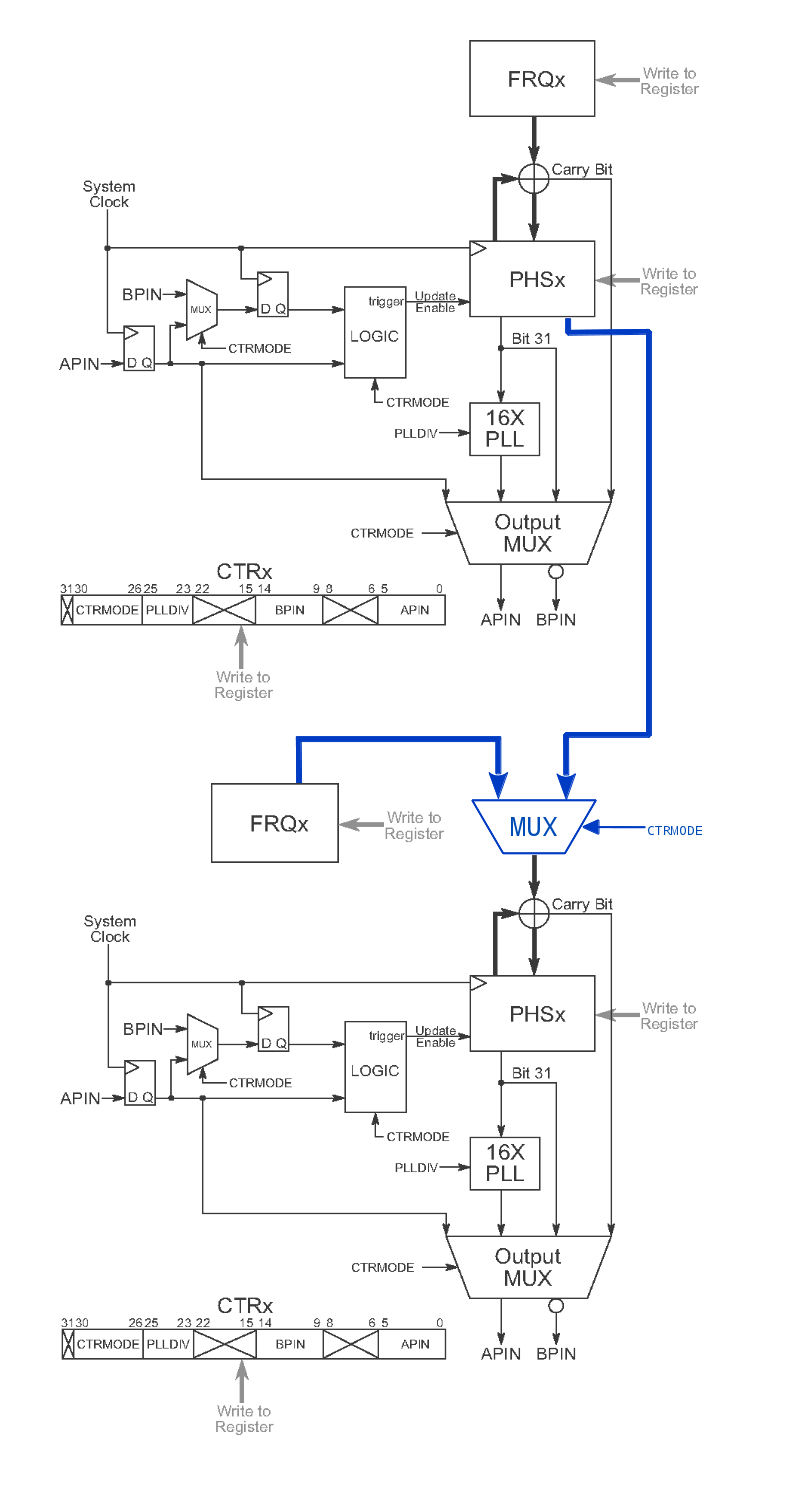
Maybe now we have Smart Pin time ;-)
Here evanh's schema for it.
Maybe now we have Smart Pin time ;-)
Comments
CLK can be generated or driven, depending on the model.
The other class of 2-line counting is Quadrature Encoders, so there could be some overlap in config setup here.
ie
Qa,Qb for 4 quadrant,
CLK,Dirn for Up/Down (1 quadrant)
CLK, CE for 1st order Sigma and general gated-counting.
by using evanh's scheme where each counters output can be muxed to the next as input even higher order can be easily achieved.
would only require one bit (or part of) in the counter config register
- and of course some code ;-)
Yes, totally (the software decimation is trivial), and each further chained counter adds, with a matching additional software cycle, the next order. However, the downside is I think the settling time also increases so multi-order capture like that pretty much can't be muxed between multiple bit-streams. The number of analogue inputs would be limited by counters.
Someone was speculating that extra orders can be accomplished all in software post processing. I wasn't able to counter such a statement but there wasn't any examples of how it would be done either.
The only reason I know this per bit-clock accelerating summing method works is because it is the standard method of extracting higher orders from ADC bit-streams. The maths is way over my head.
triadsemi.com/2007/01/25/how-to-design-a-16-bit-sigma-delta-analog-to-digital-converter/
https://maximintegrated.com/en/app-notes/index.mvp/id/1870
from this schema it looks the accumulators are clocked so it is not the whole chain who has to settle but only the stages - and that's what the couners do anyhow.
The decimation clock DEC_CLK runs much slower and can be done in SW.
So with chained counters like this a multi order SINC filter seems possible.
And if you could use the standard pin functions and use the unused counter for this - would be great.
Delta-Sigma bit stream decoder for smart-pins
But, we only have a first-order integrator. I think the only useful thing we can do is count highs over a period. We also have a counting mode that increments on this pin's high and decrements on the adjacent pin's high, for differential measurements.
evanh's schema in the first post shows - given the Prop1 counters - how counters could easily be chained to create higher order integrators
by just putting a MUX in there.
So when each smart pin has one counter
then just feeding it's output to the next pins input
would do it - right?
maybe this is possible already.
Ideally of course without loosing the default IO functions of all but the first input pin. By just using their counters.
Easy enough to type, but that 'just a MUX' is a 32 bit MUX plus 32bit data path between each pin cell adder.
Chip is trying to lower the logic cost now, not increase it.
Just wanted to make sure it is not overlooked and accidentally forgotten.
you jmg have been part of the discussion long ago ;-)
The main target for external SDM should be the common isolated ADCs ( ADI, TI etc) that have either
CLK from host + Summation Data
or
CLK to host + Summation Data
ie they are 2 pin interface devices.
Simplest handling is what is done now, aka ClkEnable a counter. That can give useful results with dual-read rates,
eg 10 MHz CLK in counter mode, gives any/all of these
~ 152 readings per second to 16b,
~38 rps to 18b,
~19 rps to 19b,
~9 rps to 20b
Flipped to give 10.00 rps, that needs 10.48576MHz clock, at 20b ADC, and you have whole cycles of 50Hz or 60Hz for mains immunity.
If you need more bits/unit time, how fast can a P2 COG do the filtering ?
Addit : Checking newer parts like ADE7912/ADE7913 , they now seem to include the filters.
These parts have an SPI inteface, and sample at 8ksps with 3 kHz signal bandwidth.
saving half of it - if there is a 'pin cell'
we'll see
That said, I do remember also coming across a statement in those datasheets stating that best results are achieved when using a filter/decimator order that is one higher than that used for the modulator. So, supposedly, the Prop2's first order modulators can still benefit from this.
That's not newer so much as bit-stream vs SPI. Bit-stream only won't have the filter/decimator while an SPI interface must have it.
That's fine done in software. The software only samples the final stage counter, and only at the decimation rate. The calculation is only an extra subtract or two at the decimation rate. It's just more of what you're already doing for first-order decimation. A Cog could do millions per second.
Ariba asks if the extra orders can not be also achieved in software after the decimation, thereby having no need of the extra hardware at all ... ?
Well, yes, but the point is more recent isolated SDM parts have the filter inbuilt, for what seems like OK prices/channel.
It seems to me those are useful if you need the 3KHz bandwidth for power harmonics etc, but for your more industrial uses, 10 sps is ok - plus that buys mains immunity, and if you need mains immunity, faster sps are not much use.
EDIT: One nice feature of the pure bitstreaming is it can be filtered to a DC level with a plain R-C filter, making for easy monitoring with a scope.
We have the following:
- A-high inc, B-high dec (relative duty)
- A-rise inc, B-rise dec (relative frequency)
- A-B encoder
We have both current and previous states of two pins to work with.
Not sure if there is anything that can be done in the SmartPin section to help USB & CRC.
Here is a link to the thread where I discussed helper instructions
forums.parallax.com/discussion/151821/usb-helper-instruction-p2-possible-additional-instructions
Phase A-B and Time interval A-B, but I think those may already be in there ?
so that when A went high, b would go high that many clocks later...
If there was a C, maybe you'd want the option that C=A or B or C= A and B, etc.
Maybe that's already there, I don't know...
On P1 we can generate a nice range of frequencies at a pin but with a 80MHz clock we can
only measure frequencies up to ~37MHz before we hit the wall.
It would be nice if P2 could internally measure/verify frequencies it has generated.
We've got this covered. The A pin can be a logical function of A and B: AND/OR/XOR, with inversion options for each input.
Ay, ay, ay.... USB. Thanks for remembering and researching this. We'd need to identify what functions are required. I know there's a complex response involving CRC that needs to be in hardware.
We've got those.
Anyone second this automatic delay function? I never thought about something like this.
Yes, we have Nyquist limitations.