

Color Space Converter
 cgracey
Posts: 14,297
cgracey
Posts: 14,297
I worked the Prop2-Hot color space converter into the current Prop2 and improved the angle resolution.
Here I slowed it down so you could see some steps.
This converter uses a 5-stage CORDIC rotator that is fed 11-bit (I,Q) values and an 8-bit angle. Since we don't have PLLs on this Prop2, a separate 32-bit NCO drives the angle.
Aside from being able to convert RGB to any analog color space, this circuit can be used as a general-purpose modulator for AM, FM, and PSK. For AM, just change the blue byte in the example above to control the amplitude. For FM, use SETMODF. For PSK, use SETMODI/SETMODQ to alter the phase (and amplitude).
I hope to get an NTSC screen running tomorrow, to make sure this is all viable without having a real PLL. I know the colorburst is okay, but it must be correlated to a 227.5-cycle scan line that is counted in main clock cycles. It will have to change between +0/+1 cycles to maintain colorburst phase. This is a different way than we did it before.
dat		org

		qfrac	##3_579_545,##80_000_000
		getqx	x
		setmodf	x		'set NTSC colorburst

		setmody	##$00_00_00_80	'lift signal to midpoint
		setmodi	##$00_00_00_00
		setmodq	##$00_00_40_00	'some blue gain

		setmod	#%11_1_0000	'YIQ mode (composite)

		setxdac	##$0000FF00	'output a blue pixel

		waitint			'wait forever

x		long	0
Here I slowed it down so you could see some steps.
This converter uses a 5-stage CORDIC rotator that is fed 11-bit (I,Q) values and an 8-bit angle. Since we don't have PLLs on this Prop2, a separate 32-bit NCO drives the angle.
Aside from being able to convert RGB to any analog color space, this circuit can be used as a general-purpose modulator for AM, FM, and PSK. For AM, just change the blue byte in the example above to control the amplitude. For FM, use SETMODF. For PSK, use SETMODI/SETMODQ to alter the phase (and amplitude).
I hope to get an NTSC screen running tomorrow, to make sure this is all viable without having a real PLL. I know the colorburst is okay, but it must be correlated to a 227.5-cycle scan line that is counted in main clock cycles. It will have to change between +0/+1 cycles to maintain colorburst phase. This is a different way than we did it before.
Comments
(Think it's something like 720x480 pixels).
Anyway, I think this is nice, if nothing else so that P2 can do everything P1 can do and better.
I can see the general purpose modulator being very useful.
BTW: Do you think P2 could decode NTSC?
Honestly, easy radio modulation might be very attractive in some circles. And with the nice DAC output, should be cleaner, easier to produce.
What is the conversion time? And I guess that gets right to Rayman's question.
The hot chip got this done pretty fast, and it had a double buffered waitvid. Once, I stuffed 2560 pixels into an NTSC scanline just for grins. It did it at 80Mhz! Way overkill obviously for SDTV, but not so much for component HDTV.
Does each cog have one or is it in the hub or the pins? How many flops/LEs is it? How much die area does it take up?
All the ingredients for QAM modulation in hardware. WOW. can't wait to try! Maybe add in the HAM radio budget and get a board. Hmmm, getting to winter... if I sell the lawn mower....
The top frequency is the Nyquist limit of the main clock, or half the main clock.
No, you maintain RGB data and it does the modulation based on some signed colorspace coefficients you provide. This is a 3x3 matrix, so nine values are needed.
Thought I was one of the few who even spoke about QAM ... Yes, I had mentioned the possibility of QAM early on as a very efficient communication method.
I made some new streamer modes, too, just for video:
1) RFBYTE as 2:3:2 RGB made into 8:8:8:0 RGB
2) RFBYTE as 8 colors / 32 luma levels into 8:8:8:0 RGB
3) RFBYTE as 256 luma levels into 8:8:8:0 RGB, 8 different sub modes provide basic colors
4) RFWORD as 5:6:5 RGB made into 8:8:8:0 RGB
5) RFLONG as 8:8:8:x RGB made into 8:8:8:0 RGB
I'm sorry I haven't documented all this yet. I've been making small enhancements here and there, but I'll get this explained soon.
Here is an 8bpp 256 x 192 image that I got the Prop2 to display tonight onto an NTSC monitor:
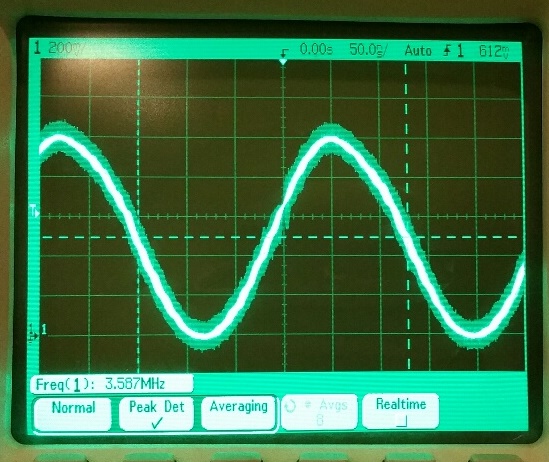
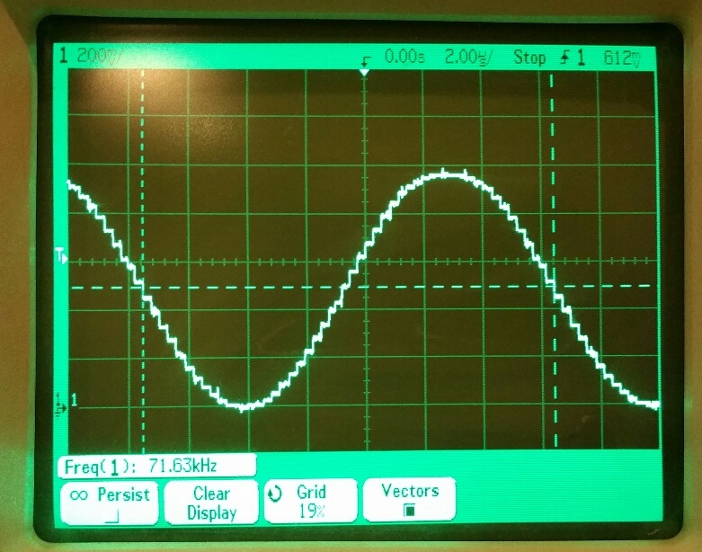
Here is some video waveform that the colorspace converter is generating to make the NTSC signal:
It turned out that correlating a colorburst signal and a pixel clock was no problem, after all. With 32-bit NCO's you can really mesh things well.
In NTSC, there is a color carrier of 3,579,545 Hz and there are 227.5 cycles of the carrier per complete scan line. That comes to 3,579,545 / 227.5 = 15,734.26 scan lines per second. After playing with different metrics, I found that 400 pixels is a good time divider for a scan line if your goal is 256 visible pixels. That frequency is 15,734.26 * 400 = 6,293,705.5 Hz.
By programming the NCO's with values to realize these frequencies, everything snaps beautifully into place, with the colorburst signal and pixel clock signal tightly sync'd at the start of every other scan line, keeping the colorburst ~180.00000-degrees out of phase on line refreshes (2 scan lines = 455 colorburst cycles = 800 pixel clocks). This was way easier than I had anticipated.
Here's the code:
'******************************* '* NTSC 256 x 192 x 8bpp-lut * '******************************* CON s = 84 'scales DAC output (s = 0..128) r = s * 78 / 128 'adjusts for modulator expansion DAT org ' ' Setup ' qfrac ##6_293_705_5,##80_000_000_0*2 getqx x setxfrq x 'set 3,579,545 Hz / 227.5 cycles per line * 400 pixels (256 visible pixels) qfrac ##3_579_545,##80_000_000 getqx x setmodf x 'set NTSC colorburst setmody mody setmodi modi setmodq modq setmod #%11_1_0000 'YIQ mode (composite) rdfast #0,##$1000-$400 'load .bmp palette into lut mov x,#0 rep @.end,#$100 rflong y shl y,#8 wrlut y,x incmod x,#$100 wc .end rdfast ##256*192/64,##$1000 'set rdfast to wrap on bitmap ' ' Field loop ' field mov x,#34 'top blanks call #blank mov x,#192 'set visible lines line call #hsync 'do horizontal sync xcont m_rf,#0 'visible line (rfword rgb16 (5:6:5) djnz x,#line 'another line? mov x,#28 'bottom blanks call #blank mov x,#6 'high vertical syncs call #vsynch mov x,#6 'low vertical syncs call #vsyncl mov x,#6 'high vertical syncs call #vsynch jmp #field 'loop ' ' Subroutines ' blank call #hsync 'blank lines xcont m_vi,#0 djnz x,#blank ret hsync xcont m_bs,#1 'horizontal sync xcont m_sn,#2 xcont m_bc,#1 xcont m_cb,c_cb xcont m_bv,#1 ret vsynch xcont m_bs,#1 'vertical sync high xcont m_hs,#2 xcont m_hl,#1 djnz x,#vsynch ret vsyncl xcont m_bs,#1 'vertical sync low xcont m_hl,#2 xcont m_hs,#1 djnz x,#vsyncl ret ' ' Initialized data ' mody long ((+38*s/128) & $FF) << 24 + ((+75*s/128) & $FF) << 16 + ((+15*s/128) & $FF) << 8 + (110*s/128 & $FF) modi long ((+76*r/128) & $FF) << 24 + ((-35*r/128) & $FF) << 16 + ((-41*r/128) & $FF) << 8 + (100*s/128 & $FF) modq long ((+27*r/128) & $FF) << 24 + ((-67*r/128) & $FF) << 16 + ((+40*r/128) & $FF) << 8 + 128 m_bs long $CF000000+50 'before sync m_sn long $CF000000+29 'sync m_bc long $CF000000+7 'before colorburst m_cb long $CF000000+18 'colorburst m_bv long $CF000000+40 'before visible m_vi long $CF000000+256 'visible m_rf long $7F000000+256 'visible rflong 8bpp lut m_hs long $CF000000+20 'vertical sync short m_hl long $CF000000+130 'vertical sync long c_cb long $687800_01 'colorburst reference color c_vw long $FFFF00_00 'white c_vb long $000000_00 'black x long 0 y long 0 ' ' Bitmap ' orgh $1000 - $436 'justify pixels at $1000, pallete at $1000-$400 file "bitmap.bmp"Is there a way to use LUT or cog ram to show an indexed color image?
2R-3G-2B for 8 bit color is nice, but could be much better as 8-bit indexed color bitmap...
Wait... Maybe I should look at your code first... I just saw this:
Did "file" directive just get added to PNut?
Yes, We could easily modulate faster than than the data could be delivered and stick it on UTP or coax for quite a long run. Decoding though, is going to be a bottleneck..
The Amateur radio implications though... WOW.
Prop SDR anyone?
The "file" directive has been there forever. I hadn't used it in a long time and I was glad to see that it still works and hadn't been inadvertently damaged, amid all the changes.
I would have done a 24bpp image, but my 'paint' program packs the pixels as 3 bytes per, so I would have had to make a decompressor. 8bpp with pallete was just was simpler. If I could get a hold a 256 x 192 image at 16bpp, I could use that straight in.
I already have code for that at home from playing with the 4.3" LCD...
This will be very nice if the same 16-bit buffer could be displayed on LCD and NTSC monitor.
Makes P2 system on a chip for portable gaming...
You can get paint.net for free, and it is a much more robust and featureful program that supports more file formats. You could use it to save out in 32bit TGA format, or even better use DDS format and specifically get XRGB (0888 32bit) and RGB (565 16bit) in one of the most easy to read forms.
http://www.getpaint.net/index.html
Also, here is the DDS format information: https://msdn.microsoft.com/en-us/library/windows/desktop/bb943991(v=vs.85).aspx
Still, looks like a pretty nice path.
Nice little UX touches in this one. (He's an Apple type guy, hiding out in MS land, it seems
Documentation is hard, in reality you just need two structures, that are rigidly defined, to read any DDS that is in any pixel format. However, most of the time you don't need the DX10 header structure (it's trivial to tell also) and can get by with just the main header.
BMPs are "simple" except for all the exceptions, which come about depending on what program you use to save the BMP.
potatohead,
I have been using Paint.Net since it first came out in 2004. It's got a massive library of plugins available for just about anything, and it just works.
Wow.
This will work equally well on PAL too ?
.. and Component Video ?
I think small composite monitors are going to be around for a long time, as they connect so readily to simple cameras.
As the 'Big Iron' parts move to support HDMI, this will be a quite significant niche for Prop 2 - Vehicles, security and monitoring are all growth areas.
How much Logic does this add ?
Will this go into every COG ?
The problem there is that you would end up with a 64-bit result.
DDS is little endian. Should be the same byte order.