

Updated 17seg LED driver for PPDB now available.
 tonyp12
Posts: 1,951
tonyp12
Posts: 1,951
Video of it here:
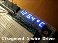
http://youtu.be/LriHbhNR0TI
Data and Latch are extracted from the Clock, as the clk does not only go low/high but have different durations.
You control it from spin the same way as the first version.
A new 2nd updated version that uses no wires, hardwired to use P0.
Cost: $16.95 each ($2.95 s&h)
To order one:
https://www.paypal.com/cgi-bin/webscr?cmd=_s-xclick&hosted_button_id=895CQGPYKCHTJ
Comments
Attached is a real-time debugger of hub ram, real useful as to monitor 3 spin variables in real-time shown as Hex (00-FF)
16bit can be shown by pairing two, and a single 24bit would use all 6 digits.
What to debug can be changed even after your program have started, just insert a new: hub1 := @xxxxx etc
In pasm to show cog ram you would insert a wrbyte at a debug point to write to the address pointed to by hub1-hub3.
I have enough pcb boards to make 50 more of these, so don't be shy with your orders (ships worldwide)
A stripped down verison of the pasm driver is used, maybe easier to follow what it does (open attached file)
CON _clkmode = xtal1 + pll16x 'Standard clock mode * crystal frequency = 80 MHz _xinfreq = 5_000_000 var word mycnt 'just an example var byte myina 'just an example OBJ LED : "DebugLED17" 'important PUB DisplayDemo | hub1,hub2,hub3'important (=var long hub1,hub2...) LED.Display(@hub1,0{pin}) 'important (send to spin part of driver) 'examples, spin is little-endian so by default you get the lower8 bits hub1 := @mycnt+1 'keep an eye on mycnt in realtime (upper 8 bits) hub2 := @mycnt 'keep an eye on mycnt in realtime (lower 8 bits) hub3 := @myina 'show the status of myina, unplug usb and you will see repeat waitcnt(clkfreq/16+cnt) mycnt := mycnt + 3 myina := ina>>24 'get the upper 1/4 bank of pins.Nice work ... it will cleanup a mess of wires in that corner of my PPDB.
I am afraid I am in the same boat as Q'bert, I completed the order without specifying the headers. I will take mine plain, and I will do the soldering.
TNX
Received my board today. Nice work. Thanks!
Yesterday, I started a project using the PPDB's L293D motor driver and I thought it would be a good chance to use the board's LED display.
The demo code worked fine but when I went to add the display code to my motor control code, the display only displayed "9B" in the first two characters with a few quickly flashing segments on some of the other characters.
The problem turned out to the passing of a byte address to the LED object. With my other code included the buffer "textBuffer" was no longer long aligned. Since this address is what gets passed to the PASM section with par, the address ends up being off by a few bytes when it's not long aligned.
There's an easy fix to this. Just add the word "long" before the buffer to force it to be long aligned.
DAT
               [B]long[/B]
textBuffer    byte "_-_-_-",0,0 '8 byte buffer but can be initial text.
text1         byte "{[HI]}",0   'can be 1-6 letters in lenght in Uppercase/0-9
text2         byte "126.4",27,"C",0
text3         byte "      HELLO THERE THIS IS A TEST      ",0
This same problem is present in the 3-pin version of the code.
I'll be making a similar post in the 3-pin version thread. The there pin version also has some issues with the way the I/O pins are set in PASM.
I cleaned up the driver too, digit interval is now a fixed 2mS for the multiplexing.
That way I don't have to worry that some bits take 1uS and some take 15uS but now still get even glow on all LED digits as with multiplexing that is important
It also have overflow error and show all E's if value is above the 6 digits decimal can show.
org 0 asm_entry mov dira,clkpin 'make only clk pin an output mov outa,clkpin 'set all pins in this cog to low but CLKpin high mov digitdelay,delay2ms add digitdelay,cnt 'copy cnt digitdelay main mov digit,#6 'we have 6 digits to multiplex mov sink, #1 'reset mosfet-to-sink pointer movs decimal,#table 'start at 100'000 rdlong myvalue,PAR 'get var from hub address cmp maxvalue,myvalue wc 'over max value? if_c mov myvalue,#0 'clear it so decimal loop don't take to long muxc error,#1 'set or clear bit0 as error overflow flag loop1 waitcnt digitdelay,delay2ms '2 ms movs fontpnt,#font 'start at "0" decimal cmpsub myvalue,0-0 wc 'try 100'000 first if_c add fontpnt,#1 if_c jmp #decimal mov bit_test,bit23 'reset bit mask so bit 23 is only set fontpnt mov serial,0-0 'start a new serial data test error,#1 wz 'error overflow set? if_nz mov serial,fontE 'replace with letter E or serial,sink 'fuse in the transistor sink bit 'inner loop starts here, send 23 clk pulses plus a long latch loop2 test serial,bit_test wz 'test serial data bitwize, set z if_nz mov cnt,delay1 'a quick clk, move 1uS to Shadow Cnt. if_z mov cnt,delay15 'a long clk (15uS), let SER dip low add cnt,cnt 'add current cnt to shadow cnt. andn outa,clkpin 'set pin low waitcnt cnt,delay30 'wait 1uS or 15uS , add 30us to cnt when done. or outa,clkpin 'set pin high waitcnt cnt,#0 'wait 30uS , add 0 us to cnt when done. shr bit_test,#1 wz 'shift right if_nz jmp #loop2 'if not zero, jmp mov cnt,delay200 'prepare a 200us delay to letting Latch go low. add cnt, cnt 'add cnt to shadow cnt andn outa,clkpin 'set pin low waitcnt cnt,#0 or outa,clkpin 'set pin high shl sink,#4 'next digit add decimal,#1 'try 10'000 next djnz digit, #loop1 'have we done 6 digits? jmp #main 'restart font long A1+A2+B+C+D1+D2+E+F+J+M '0 long B+C '1 long A1+A2+B+D1+D2+E+G1+G2 '2 long A1+A2+B+C+D1+D2+G2 '3 long B+C+F+G1+G2 '4 long A1+A2+D1+D2+F+G1+K '5 long A1+A2+C+D1+D2+E+F+G1+G2 '6 long A1+A2+B+C '7 long A1+A2+B+C+D1+D2+E+F+G1+G2 '8 long A1+A2+B+C+D1+D2+F+G1+G2 '9 fontE long A1+A2+D1+D2+E+F+G1+G2 'E bit23 long |<23 'same as %1<<23, serial bits to shift out delay1 long 80 '1us (80 MHz) delay15 long 80*15 '15us (80 MHz) delay30 long 80*30 '30us (80 MHz) delay200 long 80*200 '200us (80 MHz) delay2ms long 80*1000*2 '2ms (80 Mhz) clkpin long Pin 'value from constant above maxvalue long 999999 table long 100_000, 10_000, 1_000, 100, 10, 1 digitdelay res 1 sink res 1 'what transistor to sink myvalue res 1 error res 1 bit_test res 1 serial res 1 digit res 1Just ordered one.
Do you get PM's?
I received my board, (and thanks for the freebie), and I have a problem.
I installed it on my PPBB and downloaded the demo code. It did not do anything for 30 seconds. I then smelt the magic smoke wanting to come out of some component. Pulled the plug to investigate.
It looks like two of the shift registers where installed backwards. I would have send a picture, but the PM software does not allow it.
I will send you another one, weird that I did not see that the two IC to the right are wrong.
Hint to others: it uses 3.3v on + as Props 3.3v output will not work if the IC are on 5v (below the 70% cmos standard)
Jim
Now with no wires and works with both 3.3V and 5V
It have two pairs of holes so you can still use the power rail underneath with jumper wires.
HINT: monitoring values in pasm have always been a little harder, as you probably already have PAR/mailbox setup that you don't want to mess with.
LED17.Display ($7FFC) 'start debug_decimal_driver with a brute address (should be safe most of the time)
...
wrlong myvalue, _x7FFC 'pasm debug without using par offset
How would I purchase one?
Can you supply a populated board? If so how much would that cost?
If not is there a BOM for the needed parts, and where could I get the schematic / assembly instructions?
Thanks for your help
Tom
Tony,
Thanks; order placed.
Tom
I modified his PASM driver so that it could be used with SimpleIDE C programs, and wrote a couple of simple functions for it: Start, Test, and Clear. They along with a demo (main in the C program) are listed below along with the modified Spin/PASM code.
My intent is to build on this to add other C functions to be able to display general text and numerical results. Once I've done that, I want to make a library (libLED17) that can be included in any C program. That will take a while for me to do that, so I wanted to get my initial work on the forum.
The biggest issue was that I could not figure out a way to use Tony's constants from the Spin program (A1, A2, B, C, etc) to be used to calculate the values for all of the characters in the PASM. So I ended up calculating them and hard coding the values for all the longs in the PASM. A little bit of work, but it was successful. I also just set the PASM to use pin 0 since that's the pin the board connects to. I used Tony's format (CLKpin long 1<<0), but I assume that (CLKpin long 1) would have worked. I also did not change the hard coding for 80MHz that Tony used.
To use this, Copy the attached Spin file to the SimpleIDE directory you want. I used My projects/LED17. Make it easy to find since you will add the file to the project.
Then open SimpleIDE, select newproject and name it LED17.
Then delete all of the new project code that is entered into the editing window and copy the C code listed below into that window.
Then click on Project at the top of the screen and select Open Tab to Project. Set file types to Spin, and click on LED17v2x.spin. That code should open in the editing window in its own tab.
At that point you can save the file (to the LED17 folder). Then click on the load-ram-and-run button (after making sure the PPDB is connected and powered on and that its port shows up in the upper right hand corner window.) That will load the project to ram and it should display READY on the LEDs for about 1 second, then cycle through the characters, and finally clear the LEDs. Note that the code for test does cycle through lower case letters, but they will display as upper case.
I am relatively new to both C and Spin/PASM programming. Some of my coding is awkward. Any suggestions are gratefully accepted.
Tom
LED17v2x.spin
The C main and functions:
/*
led17.c  -- C functions for 17 segment LED on PPDB using Tonyp12 plug in driver board
T Montemarano

test harness for the libled17.c library
*/
#include "simpletools.h"                      // Library includes
// #include "led17.h"                 // for future use


char textbuffer[] = {'R','E','A','D','Y',' ',0,0};
int *cogled17;      //  pointer to cog ID

// function prototypes
void led17_start(char *text);
void led17_test();
void led17_clear();

int main()                                    // Main function
{
// Put demo code here

led17_start(textbuffer);
pause(1000);
led17_test();
led17_clear();
}


// functions
void led17_start(char *text)  // Starts PASM driver and displays "READY" on PPDB 17 segment LEDs
{
 extern int binary_LED17v2x_dat_start[];
 cogled17 = 1 + cognew((void*)binary_LED17v2x_dat_start, text);
}


void led17_test()       //  Displays all characters on the PPDB 17 Segment LEDs
{
 char text4[] = {0,0,0,0,0,0,0,0};
 for(int q =24; q<=120; q+=6)
 {
  for (int qq = 0; qq<=5; qq++) { text4[qq] = q + qq; }
  for (int qq = 0; qq<=7; qq++) { textbuffer[qq] = text4[qq]; }
  pause(2000);
 }
}


void led17_clear()      // Clears 17 segment LED display -- displays all <spaces>
{
 char text4[] = {0,0,0,0,0,0,0,0};
 for (int qq = 0; qq<=7; qq++) { textbuffer[qq] = text4[qq]; }
 pause(100);
}
The spin/PASM code:
{{ *************************************************** * LED17v2x.spin * modified from the original byTom Montemarano for use with C functions * * Original code: * LED driver v2.00 (1wire version) * * NEEDS DEMO to run, always compile from Demo tab * * Author: Tony Philipsson * * Copyright 2011 Electrons Engineering * *************************************************** }} PUB Display (text) cognew(@asm_entry, text) 'launch assembly program in a COG DAT org 0 asm_entry mov dira,CLKpin 'make only clk pin an output mov outa,CLKpin 'set all pins in this cog to low but CLKpin high main mov digit,#6 'we have 6 digits to multiplex mov buffer,par 'reset buffer (par=hub address of first letter) rdlong mytext,buffer add buffer,#4 mov byteshft,#$0 'reset the text byte pointer. rdlong mytext+1,buffer movs loop1,#mytext 'reset my textpointer movs testdot,#mytext mov sink, #1 'reset transistor sink loop1 mov mychar,0-0 wz 'get ascII char, self mod code shr mychar,byteshft and mychar,#$FF wz if_z mov mychar,#32 'if zero make it a space char(32). if_nz add byteshft,#8 'if not a zero, prepare next char for next tim cmp byteshft,#32 wz '4 bytes in a long if_z add loop1,#1 if_z add testdot,#1 if_z mov byteshft,#0 cmp mychar,#123 wc 'check if it's char({) or higher if_nc add mychar,#6 'adjust for the sub 32 below cmp mychar,#97 wc 'check if it's char(a) or higher if_nc sub mychar,#32 'our font table have a-z omitted. ' sub mychar,#24 'subtract as our ascii table start at char(24) movs fontpnt,#font 'reset font pointer add fontpnt,mychar 'add ascii code that mytext have, to font pointer mov bit_test,#1 'reset bit mask shl bit_test,#23 'we have 23 bits to shift out fontpnt mov serial,0-0 'start a new serial data or serial,sink 'fuse in the transistor sink bit testdot mov mychar,0-0 wz 'get ascII char, self mod code shr mychar,byteshft and mychar,#$FF cmp mychar,#46 wz 'test if the next char is a dot if_z or serial,mydot if_z add byteshft,#8 'skip this char next time cmp byteshft,#32 wz if_z add loop1,#1 if_z add testdot,#1 if_z mov byteshft,#0 'inner loop starts here, send 23 clk pulses plus a long latch loop2 test serial,bit_test wz 'test serial data bitwize, set z andn outa,CLKpin 'set pin low mov cnt,cnt 'copy current cnt to shadow_cnt if_nz add cnt,#80 'a quick clk, keep SER high if_z add cnt,delay15 'a long clk, let SER dip low if_nz waitcnt cnt, delay15 'wait 80 ticks, add 15us to cnt when done. if_z waitcnt cnt, delay30 'wait 15us, add 30ms to cnt when done or outa,CLKpin 'set pin high waitcnt cnt, #0 'wait the 15us or 30us set above shr bit_test,#1 wz 'shift right if_nz jmp #loop2 'if not zero, jmp andn outa,CLKpin 'set pin low mov cnt, cnt 'copy cnt to shadow cnt add cnt, delay200 'prepare a 200us delay, letting Latch go low. waitcnt cnt, delay300 'wait 200us, add 300us to cnt when done. or outa,CLKpin 'set pin high. Add any of YOUR CODE between this.... waitcnt cnt, #0 'and this line, change delay300 up to max 1800 if needed. shl sink,#4 'next digit djnz digit, #loop1 'have we done 6 digits? jmp #main 'restart font long $24A0C4 'Pund , start our font at Char(24) long $24C800 'Yen long $24A6C6 'Euro long $202402 'degrees long $4E00 ' long $24A0C0 ' long $E2000 ' arrow up long $46800 ' Arrow down long $0 ' Space long $28 '! long $2400 ' " long $2EEEEE '# (all 16 on) long $24A4E6 '$ long $2CE462 '% long $C60E4 '& long $4000 '' long $24000 '( long $80800 ') long $2EE800 '* long $24A000 '+ long $80000 ', long $208000 '- long $400000 '. long $84000 '/ long $846EE '0 long $28 '1 long $2082CE '2 long $80EE '3 long $208428 '4 long $2204C6 '5 long $2086E6 '6 long $2E '7 long $2086EE '8 long $2084EE '9 long $42000 ': long $82000 '; long $24000 '< long $2080C0 '= long $80800 '> long $4800C '? long $A6CE '@ long $20862E 'A long $4A0EE 'B long $6C6 'C long $420EE 'D long $2086C6 'E long $200606 'F long $86E6 'G long $208628 'H long $42000 'I long $2E8 'J long $224600 'K long $6C0 'L long $4E28 'M long $20E28 'N long $6EE 'O long $20860E 'P long $206EE 'Q long $22860E 'R long $2084E6 'S long $42006 'T long $6E8 'U long $84600 'V long $A0628 'W long $A4800 'X long $44800 'Y long $840C6 'Z long $42044 '[ long $20800 '\ long $42082 '] long $8400C '^ long $C0 '_ long $800 '` long $242044 '{ long $42000 '| long $4A082 '} long $208208 '~ long $486EE 'CR CLKpin long 1<<0 '<<CLK hard coded for tonyp12 PPDB 17Led plugin board -- P0 delay15 long 80*15 'hardcoded for 80mhz prop delay30 long 80*30 'will read hub $0 in next version. delay200 long 80*200 delay300 long 80*300 mydot long $400000 sink res 1 'what transistor to sink mytext res 2 'reserve 8 bytes (2 longs) mychar res 1 byteshft res 1 buffer res 1 bit_test res 1 serial res 1 digit res 1 fitI've also cleaned up some of the C programming (I'm learning about strings in C).
Tom
/* led17.c -- C functions for 17 segment LED on PPDB using Tonyp12 plug in driver board T Montemarano test harness for the libled17.c library */ #include "simpletools.h" // Library includes // #include "led17.h" // for future use // Global variables char textbuffer[] = {'R','E','A','D','Y',' ',0,0}; int *cogled17; // pointer to cog ID // function prototypes for library void led17_start(char *text); // param (pointer to character buffer for PASM) void led17_test(); void led17_clear(); void led17_pnumi(int); // param (integer to display) int led17_p3208i(int, int, int); // params (int channel_number, int adc_raw, Vref), returns volts*1000 // function prototypes for demos void test_pnum(); void adc3208sim(); // simulates raw output of MCP3208 int main() // Main function { // Put demo code here led17_start(textbuffer); // start PASM driver pause(1000); led17_test(); // Display all ASCII characters, 6 at a time led17_clear(); // Clear display pause(1000); test_pnum(); // demo display of numbers and error if num places > 6 pause(1000); led17_clear(); // Clear display adc3208sim(); // Simulate MCP3208 readings and display volts as ch#<space>x.xxx pause(1500); led17_clear(); // Clear display pause(1000); } // end main // ************* functions void led17_start(char *text) // Starts PASM driver and displays "READY" on PPDB 17 segment LEDs { extern int binary_LED17v2x_dat_start[]; *cogled17 = 1 + cognew((void*)binary_LED17v2x_dat_start, text); } // +++++++++++++++++++++++++++++ void led17_test() // Displays all characters on the PPDB 17 Segment LEDs { char text4[] = {0,0,0,0,0,0,0,0}; for(int q = 24; q <= 120; q+=6) { for (int qq = 0; qq<=5; qq++) text4[qq] = q + qq; strcpy(textbuffer, text4); // move string to PASM buffer pause(2000); } } // +++++++++++++++++++++++++++++ void led17_clear() // Clears 17 segment LED display -- displays all <spaces> { char text4[] = {0,0,0,0,0,0,0,0}; strcpy(textbuffer, text4); // move string to PASM buffer pause(100); } // +++++++++++++++++++++++++++++ // ** note uses sprinti because sprintf adds 11k bytes to total code size // if necessary to use sprintf -- put those functions in separate file for library void led17_pnumi(int x) // Displays an integer <= 6 digits incl sign or ERROR if > than 6 digits { // Number is displayed left justified char buffer[20]; char text4[] = "ERROR "; int n = sprinti(buffer, "%d", x); // convert number to string, n is length if(n > 6) { strcpy(textbuffer, text4); // move ERROR to PASM buffer return; } strcpy(textbuffer, buffer); // move string to PASM buffer return; } // +++++++++++++++++++++++++++++ int led17_p3208i(int ch, int adcraw, int vref) // convert raw to volts & display "ch x.xxx" { // params (int channel_number, int adc_raw, Vref), returns volts*1000 char buffer[] = {0,0,0,0,0,0,0,0}; int vx1k = (adcraw * 1000 * vref) / 4096; // volts * 1000 int n = sprinti(buffer, "%d _%d", ch, (vx1k + 1000)); // add 1k to protect leading zeros buffer[2] = buffer[3] - 1; // remove 0 protection, move 1st digit to make room for DP buffer[3] = 46; // insert the decimal point strcpy(textbuffer, buffer); // move string to PASM buffer return vx1k; } // +++++++++++++++++++++++++++++ void test_pnum() { for(int i = 1; i <= 10; i++) { led17_pnumi(2123 * i * i * i); pause(1500); led17_clear(); // Clear display } } // +++++++++++++++++++++++++++++ void adc3208sim() // simulates raw output of MCP3208 for demo { int vv; int vraw[] = {5, 1024, 1536, 2048, 2560, 3072, 3584, 4096}; for(int i = 0; i <= 7; i++) { vv = led17_p3208i(i, vraw[i], 5); // ch#, adc raw value, reference voltage printi(" Channel %d = %d volts x 1000\n", i, vv); pause(1500); } }-Mike
Do you know where the schematic is for these led's on PPDB?
Led part # is 3292AB
Thank you!
Merry Christmas!
They are common cathode. Ground the cathode and pull the segment high. Resistors are included
Thank you.
How do you wire it?
Merry Christmas!
I posted one previously here: http://forums.parallax.com/discussion/111067/sixteen-segment-display-on-popeller-professional-development-board
Here is the pcb diptrace file.
This is the latest version that don't use any wires.
Buffer (SN74LV1T34DBVR) so it will work with any power-rail voltage.
Dual n-mosfet CPH5617-TL-E
Two resistor-capacitor network as to trick data and latch pins to not see the fast clock signals, as pcb only uses fast, slow and super-slow clock signal.
Tony, Thanks for sharing the Diptrace file!