

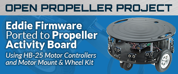
Open Propeller Project #8: Eddie Firmware Ported to Propeller Activity Board
 Ken Gracey
Posts: 7,420
Ken Gracey
Posts: 7,420
Background to this Open Propeller Project
Today we launch a new Open Propeller Project (#8) to improve the Eddie firmware so that Parallax Arlo users have an effective Spin solution with the new Motor Mount and Wheel Kit with Encoder. At present, we have only released C code in the SimpleIDE framework which is adapted from the ActivityBot. However, many customers prefer Spin and we would like to support their requests. We also have many Eddie Control Board customers using ROS, who would benefit from a Propeller Activity Board compatible version of the Eddie Firmware.
WIth this code, we will be one step closer to releasing the Arlo Robotic Platform as a complete kit, to Parallax standards. Customers will be able to use the Motor Mount and Wheel Kit effectively on platforms of their own making, too.
Challenge Details
The author of the original Eddie Control Board firmware (David Carrier) has written up some notes on what it will take to complete a few challenges:
- Challenge 1: (Trivial) Modify the Eddie Firmware code to work with a Propeller Activity Board, two HB-25s, and a Motor Mount & Wheel Kit.
Programmatically, the only variations from the Eddie Control Board board are a different ADC and H-bridges with built in controllers. Replace the MCP3008 with ADC124S021 code and swap out the H-bridge controller code in "Eddie Motor Driver.spin" with a servo-pulse output, and you’ll be done. Make sure everything is compatible with the original code, including the motor power levels in "Eddie Motor Driver.spin"
- Challenge 2: (Not so trivial) Add in the "ARC" command that was never finished.
The code in the "POSITION" section of the case statement in the PDIteration method drives the robot in a straight line while ramping motor speed up and down smooth. An "ARC_POSITION" case would drive the outer wheel using essentially the exact same code, but the inner wheel would need to move proportionally slower.
This is where copy and paste are your friend. Use a copy of the existing code to drive the set point for the outer wheel, but base the set point for the inner wheel on percentage of the distance the set point of the outer wheel has traveled; don’t let the inner wheel ramp on its own. The "TRVL" and "TURN" commands in the "Parse" method are similarly reusable. An "ARC" command would be mostly an amalgam of the two.
Make sure the units match. The "TRVL" command uses encoder positions as a unit of distance, so the turn radius should do the same. This will take some math. The POSITIONS_PER_ROTATION constant will help you here. Pay attention to how the "TURN" and "HEAD" commands use it.
- Challenge 3: (Far from trivial - a technical stretch goal) Add an integral into the proportional/derivative control code.
Currently, the Eddie code will happily sit one position awn4cb805day from its destination, since it doesn’t accumulate error over time. This isn’t accumulative and doesn’t effect dead reckoning, so it isn’t a high priority, but if anyone feels the need to correct it, I don’t think anyone would mind.
This project has been one of those important efforts that we have always felt we can complete internally, but competing priorities have caused it to continually take second place [and never be completed]. We are also actively recruiting more internal and consulting engineering resources for our team. This project, along with the other Open Propeller Projects, has helped us develop additional productive relationships.
Parallax GitHub
The source code repository for this project will be in the Parallax GitHub. Parallax is in the process (as of November 1, 2014) of moving all of our community open source code development efforts to this GitHub. All code will be open source under MIT license (copy and paste the license from other code into this one). The original Eddie code didn’t have the MIT license because it was created for Microsoft.
We will create the GitHub repository for these files on Tuesday this week.
We’ll Support this Effort with Hardware
Our hardware platform is basically defined above as an Arlo Robotic Platform. We would happily provide up to three (3) additional sets of Motor Mount and Wheel Kits and HB-25s to productive contributors. If you’re a contributor to this project we would be happy to provide the hardware for your efforts.
Additional Resources
Eddie Spin code http://www.parallax.com/downloads/eddie-board-command-set
Ken Gracey
Parallax Inc.
Comments
I'm very interested in motor control algorithms. If you were to send me the hardware, I'll put a lot of effort into these challenges.
I've previously had some success with motor control using encoder feedback with my Mecanum wheeled robot project.
Fish on! I mean, ahem, "yeah, we got Duane!". I know you can do this project from your prior work with the ESC programming.
Hardware shall be dispatched on Tuesday.
Maybe we need one more interested and capable party to assist you as a tester/collaborator on this project.
Ken Gracey
Absolutely. It would be great to work with some other Parallaxians.
I have the hardware so I'll keep a eye on this.
Brian
Welcome back, Brian! Now that summer is over we'll be happy to see ya back on the forums. Thank you for the time this morning answering some non-electronic questions, too.
We should be posting the WiFi/iOS stuff pretty soon, too.
Ken Gracey
it's always a pleasure to chat with you.
Summer is always a super busy ,so my robots ( and the forums) take a back seat.
I pulled out my Arlo and noticed I have a propeller BOE board running it ,so I could use another Propeller activity board to make it code compatible.
Brian
The previous ADC code ran continuously in its own cog, JonnyMac's adc124s021 only reads from the chip when requested. It wouldn't be hard to convert Jon's code to continuously update the ADC variables but from my initial inspection of the Eddie code, I don't see a reason to tie up a cog to read the ADC chip.
Will the PC software mind if only four values are returned from the "ADC" command? Should there be eight values returned? If more than four values are returned, what should the extra four fields consist of?
IMO, if it's best to return 8 values, then the four readings from the ADC should be repeated. This way the last channel can still be used to monitor the battery voltage without needing to change the code on the PC end.
Unless instructed otherwise (UIO), I'll have the ADC command return the four channels listed twice. Also, UIO, I don't have the ADC code running continuously. The chip will only be polled when requested.
I agree with you in both of your "UIO" assumptions. I think the MCP3008 object was designed for oscilloscope-like functionality. Since the Eddie firmware only reads from the ADC occasionally, I think it makes sense to do the readings inline instead of tying up a cog.
With the VERSION constant, we usually increase the first digit any time we break compatibility and the second for each release since then. I recommend setting the version [14] if you double transmit the ADC results and version 20 if you only return four values.
— David Carrier
Parallax Inc.
Robert
Also, if your going to "double stamp" the data, make it so that the data packet sent is the Previous data along with the Current data or the delta (first derivative) between the previous data and current data. This can be useful in predicting acceleration deceleration trends.
Another also .... can someone remove the (Parallax) from my name without destroying my forum account? Thanks
The latest version uses the "13" as the version number.
It looks like version 1.3 includes code to read the new quadrature encoders. Do you know if version 1.3 is working properly with the Eddie board's h-bridge?
If the quadrature encoder portion of the code works properly, then besides the change in the ADC (which should be trivial) then the other main change is to convert the h-bridge code to use servo pulses, correct? If this is the case, then the motor control change will also be trivial.
I take it Dynamic PWM is above what is done with a PID loop? I'd think the encoders would indicate when additional power is needed to overcome an unexpected load.
Would Dynamic PWM be practical with the hardware Ken listed? If so, it would require two of the four ADC channels, correct?
Robert
I'm using a stripped down version of Beau's servo object with the variables moved to a DAT section so the object can be shared among several other objects.
This would allow the use a command to set servo positions without much additional overhead.
I was thinking about jury rig something together to test the changes but I think I'll wait until the hardware arrives.
As I saw Duane has made a "Stingray Like" robot that is very similar (design geometry and hardware) as the artist
I visited Parallax GitHub but I couldn't find the code Eddie=>Arlo. Is the code there?
Wow, you're right. Our robots do have a similar geometry (and hardware). Here's my robot.
And below is a photo I borrowed from your robot page showing your The Artist next to your Stingray.
I drew the design on the PC using Arlo's size as a guide. The distance between the wheels on my robot should be the same as on an Arlo. I used the distance between the wheels as the size of an octagon but then stretched the octagon out for the tail. The tail wheel (while turning) should fit within the diameter of a circle described by the two main wheels. I had the Stingray in mind while designing my robot but I didn't look up the design of the Stingray before drawing my bot. I can now see the angles of my robot and the Stingray aren't exactly the same. Five of the sides of my robot make up most of an quadrilateral octagon. One of my main desires was to get the design finished quickly while still matching the wheel spacing of the Arlo.
Here's the drawing of my bot with a circle the size of an Arlo to give one an idea of the size difference.
So while the distance between the wheels is the same on my robot as on an Arlo, my robot has a lot less deck realestate.
I cut my platform from some expanded PVC.
Once I make some significant progress with the software, I'll work on making the hardware more presentable.
I'm pretty sure I'll want to add a second deck.
I have the ADC part of the Eddie code modified to use the Activity Bot's ADC chip and I can use the "POWER" mode commands to drive the motors but the encoder feedback portion of the code still needs some work (it may need lots of work).
I'm still not sure how the GitHub stuff is going to work with this project. I'll do what Parallax wants but until we (or just I?) get this figured out, I'll post my most recent code here.
Once I have a version of code I can be relatively sure won't cause damage to the attached hardware, I'll post it.
It looks very nice!
Have you found where the gravity center is?
When you put the AX-12 Smartarm on the chassis in which point the Robot balances?
Pay attention at this point if you want to have a good stability.
The "Smartarm" outline was added to see if the robot would be large enough to carry it. I understand I'd need to make some changes to the robot if I add the Smartarm.
As the robot is now, the center of gravity is behind the main wheels. I've only powered it one while up on blocks so far. Once I get the ARC command to work, I'll have the robot perform a figure 8.
Once I figure out what I'm supposed to do with Github, I'll submit a "push" (is that right?).
I don't consider this project finished at all but I thought I'd post what I have so far in case any of you are interested in seeing it.
One of the parts which is currently broken is the timeout code which would turn off the motor if communication from the PC stops.
This is the section I broke (starting on line 325):
repeat                                                ' Main loop (repeats forever)    NextCNT := PROCESSRATE + cnt
    repeat while (rxcheck := Term.rxcheck) < 0          ' Read a byte from the command UART
      LoopCount++
      '''if KeepAlive and LoopCount > constant(_clkfreq / PROCESSRATE)' Stop motors if no com in one second
      if KeepAlive == 0
        ifnot PDRunning
          Motors.Stop
          if debugFlag
            Term.Str(string(13, "Motors Stopped"))
        waitcnt(constant(_clkfreq / DIVISOR) + cnt)
        SetPower[LEFT_MOTOR]~
        SetPower[RIGHT_MOTOR]~
        StillCnt~
        Mode := POWER
      else
        'waitcnt(NextCNT += PROCESSRATE)
In order to speed the debugging process, I'm interacting with the program through the Parallax Serial Terminal(.exe).
Besides disabling a portion of the program to make it easier to interact through the terminal, I also added some "features" to make it easier for me to debug the code.
The following three variables when set to one will make the output to the terminal easier to read and input easier as well (the input and output can be decimal ASCII instead of hex ASCII).
Here's an example of the output with these flags set to one.
The code required some significant (but easy) modifications to work with the HB-25 motor controllers. I added the "activeParameter" variable to make it easy to adjust some of the motor control parameters while the program was running.
I added so many of my own commands the limit of 15 (or is it 16?) elseif conditions was starting to make the long list of string comparisons awkward. I was initially going to separate the list of "elseif" checks into methods with 16 conditions each but I decide if I were breaking the list apart anyway, I might as well cut down on the number of conditional statements each command entry required. I ended up grouping the commands by sections of the alphabet.
  case InputBuffer[0]
    "A".."F":
      ParseAF
    "G".."K":
      ParseGK
    "L".."R":
      ParseLR
    "S".."Z":
      ParseSZ
    other:
      abort @InvalidCommand
The above code branches the program based on the first letter of the command. The commands starting with "A", "B", "C", "D", "E" and "F" are all listed in the method "ParseAF".
I wrote some comments about the commands I added near the top of the program in the "CON" section. I figure most of these added commands will be removed once the code is working properly.
I've started work on the ARC command but the code isn't included in the attached archive. I haven't started work on the integral aspect of the control algorithm but I'm written this sort of code before so I'm hopeful I'll be able to make it work.
This is pretty amazing code. One can enter the distance and speed to travel and the code "magically" powers the motors at the appropriate level. It's been fun to work on this project.
Edit (December 27, 2014): See post #36 for the latest version of the code.
Edit(12/29/14) To reduce confusion about which code to use, I'm leaving only the latest versions attached to post #36.
I ordered a activity bot board yesterday to replace my BOE board on my "Arlo". I'll test your code as soon as I can.
Brian
I borrowed the S2's sound code so the robot could produce sounds with a command "SONG".
I haven't cleaned the code up in a while but I think the attached code should work with the original commands.
Here's a video of the robot performing a figure 8 using the new "ARC" command.
Edit(12/29/14) This is an early test video. To see the most recent version of the firmware in action watch the video embedded in post #41.
The difference between the code attached and the code used in the video is I had the "demoFlag" set to 1 so the demo (driving in a figure 8 and spinning in place) would start without any input on my part.
Once I have the code working a bit better, I'll start removing some of the extra code I added.
Edit: I think I've figured out how to add photo inline again. Here are the attached images.
Edit (December 6, 2014): As mentioned in the comment section of the Eddie141121a code, the "SERVO" command had not been tested. I have since tested it and it does NOT work. I have since fixed it and I'll be posting an update with the fixed code soon.
Edit (December 27, 2014): See post #36 for the latest version of the code.
Edit(12/29/14) To reduce confusion about which code to use, I'm leaving only the latest versions attached to post #36.
Edit(4/19/20): Fixed image links and YouTube link.
Besides the overall shape being different, I decided to use straight lines to make the cutout for the motor instead of Arlo's oval shaped cutout.
In case anyone is interested, here are the coordinates of the cutout (0,0 is top left)(units are millimeters).
The zipped OpenOffice drawing is attached to this post.
I didn't add a lower level (used as a battery holder on the Arlo) since I didn't want to reduce the ground clearance of the robot.
It appears there is 10cm of clearance between the platform and the ground.
Now that I look at the above photo, I can see why the battery holder platform is a good idea. The wheels on my bot look like they angle outward a bit. I may need to figure out a way to better support the motors/wheels when I add additional weight to the robot.
After recently reading through NikosG's Artist thread, I think I'll try to copy some of the features (I already inadvertently copied the shape) of the Artist and add a hole in the center of the robot to use with writing instruments.
Hopefully I can make as easy to draw shapes using this Spin code as NikosG's has made it with the available C code.
Edit(4/19/20): Fixed embedded images.
Duane,
Indeed a lower level like the battery holder on the Arlo is necessary......
Without a second hold (surbase) the wheel kit tremble as the robot moves fast or turn around (I saw that in my Robot)
Unfortunately I haven't done nothing with the writing code..... I'm still waiting some accessories from e-bay in order to make the painting mechanishm....
I decided I wanted my robot to be a bit more interesting so I started adding sensors to it.
I added a couple of Pings but I was having trouble making sense of the feedback from the Ping sensors.
One issue I had was the description of the units in the documentation. Both Eddie Command Set documents version 1.1 and 1.2 use this description under the "PING" command:
So the values returned from the PING command are between 18 and 2900 inclusive.
If the above is correct then the maximum reading of 2900 should equal 6.168mm. Obviously there's an error.
I think if you divide these conversion factors by 512 (9-bits) then you get closer to the correct conversion factor.
Instead of 470.2 units per mm, the conversion factor is 0.91836 units per mm. If the values in the "Ping.spin" object are correct:
Then the conversion factor should be 0.90698 units per mm (if I did my math correctly).
It's not surprising to find small discrepancies among time to distance conversion factors since these conversions are dependent on the value used for the speed of sound. The speed of sound is strongly effected by temperature.
Since I wanted to change the way the Ping sensors were triggered and read anyway, I decided to modify the original Ping.spin code in the Propeller library to include a method allowing for temperature compensations. (I understand the way the Eddie firmware reads from the Ping sensors is very different than the way used by the Ping object in the Propeller library.)
I've posted my version of the Ping code in the Propeller forum.
Part of my desire to change the Ping section of the Eddie code is to reduce (or hopefully eliminate) the problems of echos from one Ping sensor interfering with another. The present Eddie code triggers the Ping sensors in a way which is prone to interference.
I have not finished incorporating my changes into the Eddie code yet. I still need to make my Ping object backwards compatible with the earlier Ping object.
As mentioned in an edit to post #24, the "SERVO" command does not consistently work. I have fixed this issue and the fixed code will be included in my next update. This next update will occur once I have the new Ping object successful incorporated into the Eddie code.
One question I have for Parallax is about the units used with the "PING" command. Since the present documentation is not correct about the conversion of returned values to actual units of millimeters and inches, I'm wondering if it would be okay for the "PING" command to return the distance reading in millimeters rather the 1/512 of the clock cycles the pulse takes to reach the obstacle and back. The present units are already 90% the value the units will have if millimeters are used.
If Parallax would like the units to remain the same, then perhaps a command could be issued to switch to alternate units?
I should have a version of code incorporating the new Ping object to upload within a couple of days. The next version will also include the fixed "SERVO" command.
I'm anxious to get these small things done so I can get to work on the real problem of incorporating an integral component to the motor control algorithm.
This update doesn't really do much more than the previous code. I did fix the "SERVO" command and the Ping sensors are no long triggered all at once (which caused interference). I still don't have an integral component to the control algorithm yet. Edit: See post #36 for code which includes an integral component.
I think the big change with this version is it may be used with either the original Eddie Control Board or the Activity Board by changing a single line of code.
OBJ

  Header : "HeaderEddieAbHb25Encoders141225a"
  'Header : "HeaderEddieHbridgeEncoders141225a"          ' uses one cog
I wired up a h-bridge to the robot so I could test the code using the same pinouts as the Eddie Control Board. I used a QuickStart board as the control board with the h-bridge since the Activity Board didn't have the I/O pins available which were used by the Eddie Control Board.
Being able to run the version 1.3 code was really helpful. I could see how well the code worked and use it as a comparison for the code I was working on.
There are a lot of changes to the code but most of the changes are superficial and cosmetic. I've personally gotten used to using the formatting suggested by the Parallax Gold Standard so I changed the code to match the Standard's formatting. I also changed many of the variable names and constant names in an attempt to understand the code. I hope these changes are not too annoying to anyone.
I don't have time to list all the changes now or why they were made. Many of the changes were made in preparation of implementing what I hope is a better PID algorithm.
Here's a video of my robot running though some of the navigation commands. The "ARC" command (which now supports reversed directions), the "TURN" and "TRVL" commands are also demonstrated.
Edit(12/29/14) This is an early test video. To see the most recent version of the firmware in action watch the video embedded in post #41.
The firmware using the Eddie Control Board is named "EddieBxxxxxxx" ("xxxxxxx" is the version date and letter) and the firmware or the Activity Board with HB-25 motor controllers is named "EddieCxxxxxxx". If I get the position encoder version of the firmware figured out I'll add an "EddieA" firmware version.
There are still lots of changes I intend to make but I wanted to get something up for people like JackJack.
Again the "B" version uses the Eddie's h-bridge and the "C" version uses an Activity Board and HB-25 motor controllers. I haven't tested the B version's ADC command yet.
If the "demoFlag" variable is set to 1, the robot will start driving the course shown in the video.
Edit: See post #36 for the latest version of the code.
Edit(12/29/14) To reduce confusion about which code to use, I'm leaving only the latest versions attached to post #36.
I tried to run the video and got the response "this video is private"
Jim
Thanks for letting me know. I thought I saw it say "Public" when I posted it. Hopefully it's working now.