

Scara robot using servos and hardware store components (Video)

My latest project is a Scara robot which is a robot arm that works in a horizontal plane. It's anthropomorphic because it has a shoulder and elbow joint, but usually the end effector just moves up and down rather than the arm as a whole. This arrangement simplifies control over a revolute coodinate arm, but inverse kinematics are still helpful. In the general discussion forum I posted a FORTH program to do inverse kinematics using fixed point trig. My previous IK robot arms used C++ with floating point, but I want to use FORTH this time to allow interactive control like my FORTH powered drawbot.
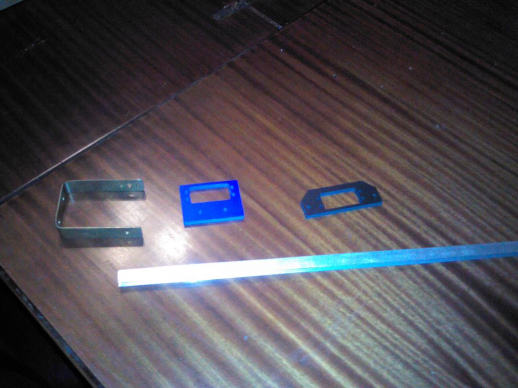
I had planned to wait until I completed this project before writing it up, but I decided documenting as I go will help keep me motiviated. If anyone else is interested in building one feel free to ask questions. Any suggestions (particularly about the end effector) would be welcome too. Here's the bill of materials:
Again this is a much simplier build than a revolute arm. Here's what I've done so far:
1. Cut two 7" pieces of U channel and drill 4-40 size holes every 1/2" to allow for experimentation with mounting.
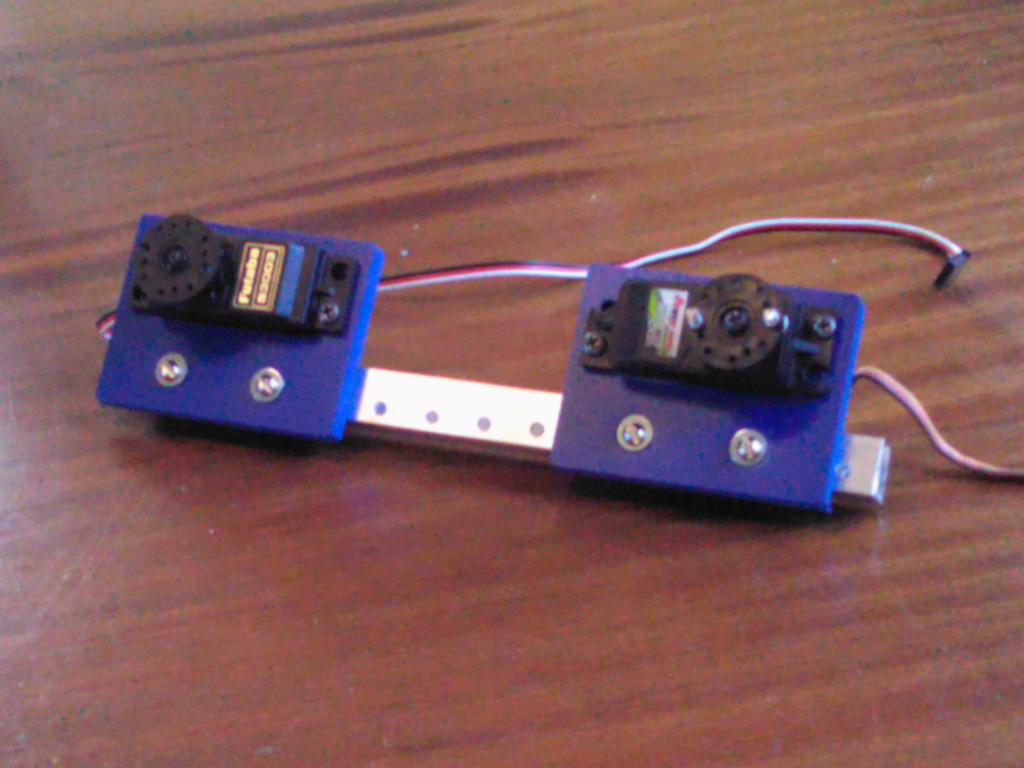
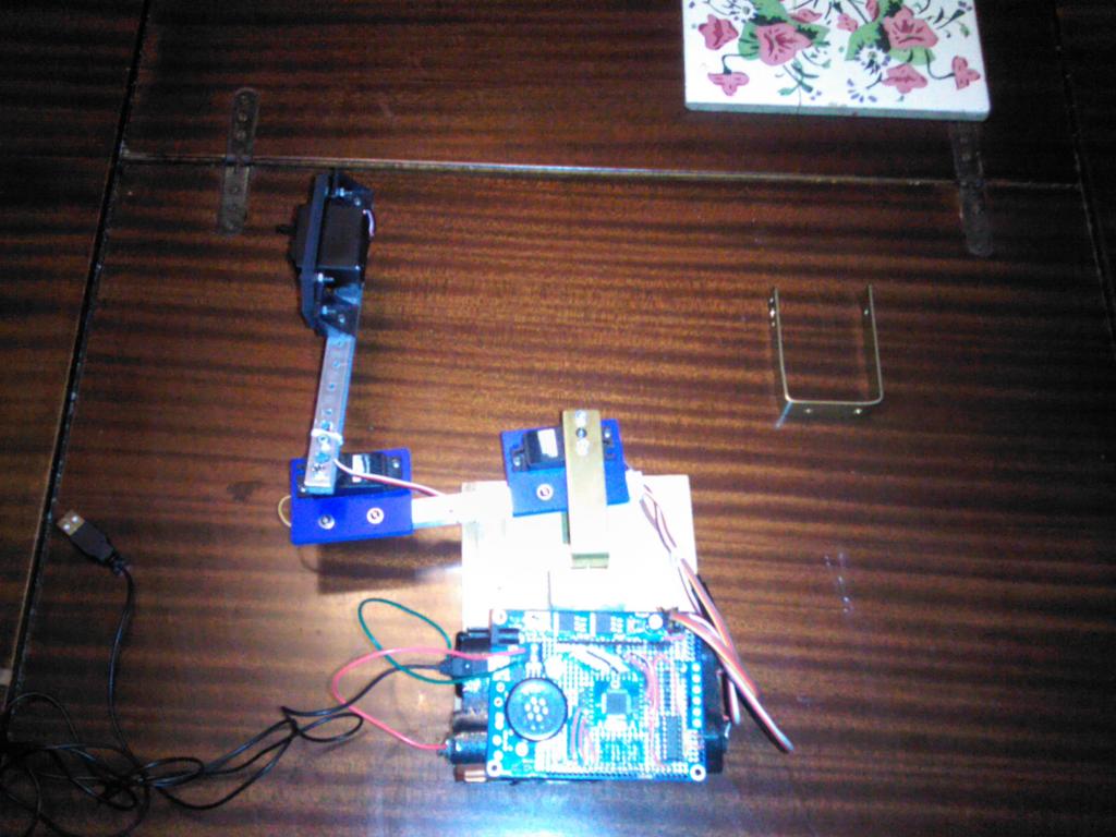
2. On the first piece of U channel mount two servos using servo brackets. Here's a picture:
3. On the second piece of U channel enlarge a hole to allow access to a servo spline screw.
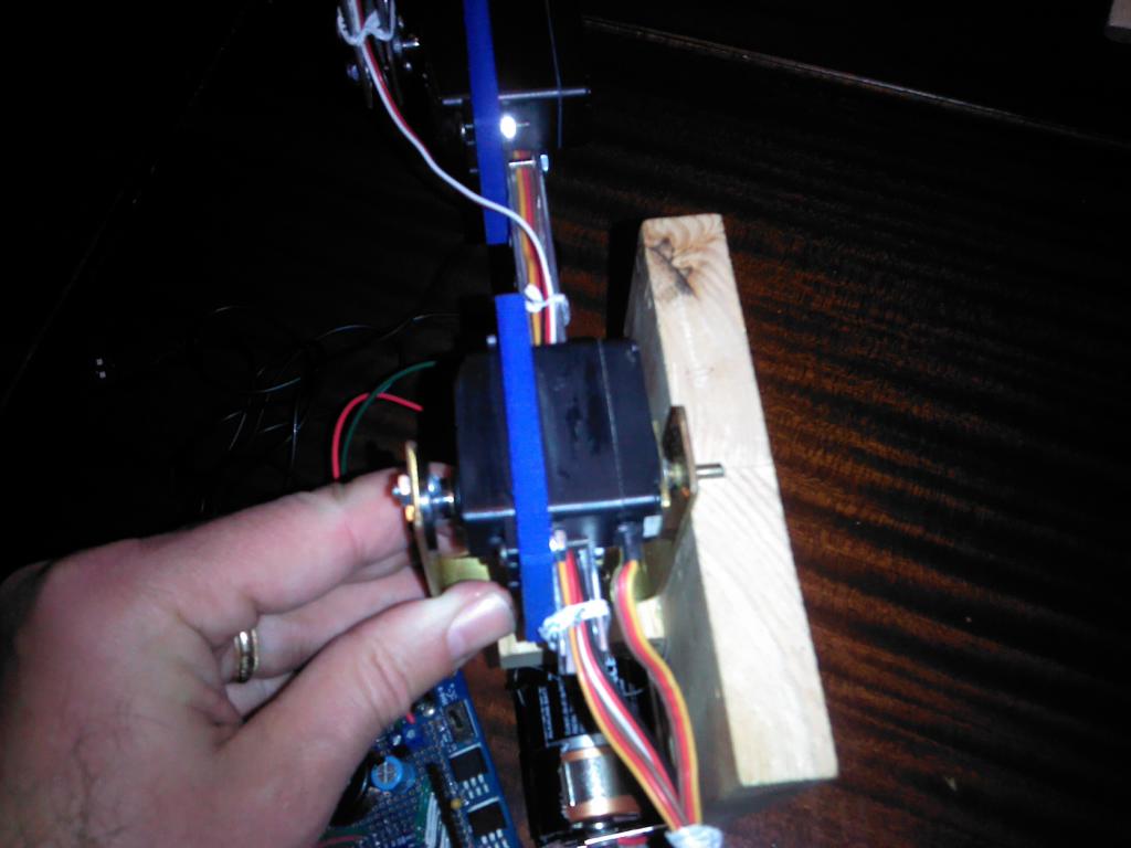
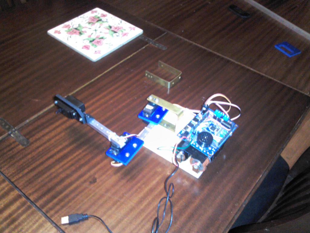
4. Make or buy a bracket to create a yoke for the shoulder joint. I make my own and glue a screw to the bottom of the servo to create the idler pivot. You can see the bracket in the first picture and the mounting below.
5. Screw the bracket to the wooden base, screw the servo horn to the bracket, and mount the servo bottom pivot. Use your strongest servo for this joint as it will be bearing the largest load.
6. Screw the second piece of U channel to the second servo horn.
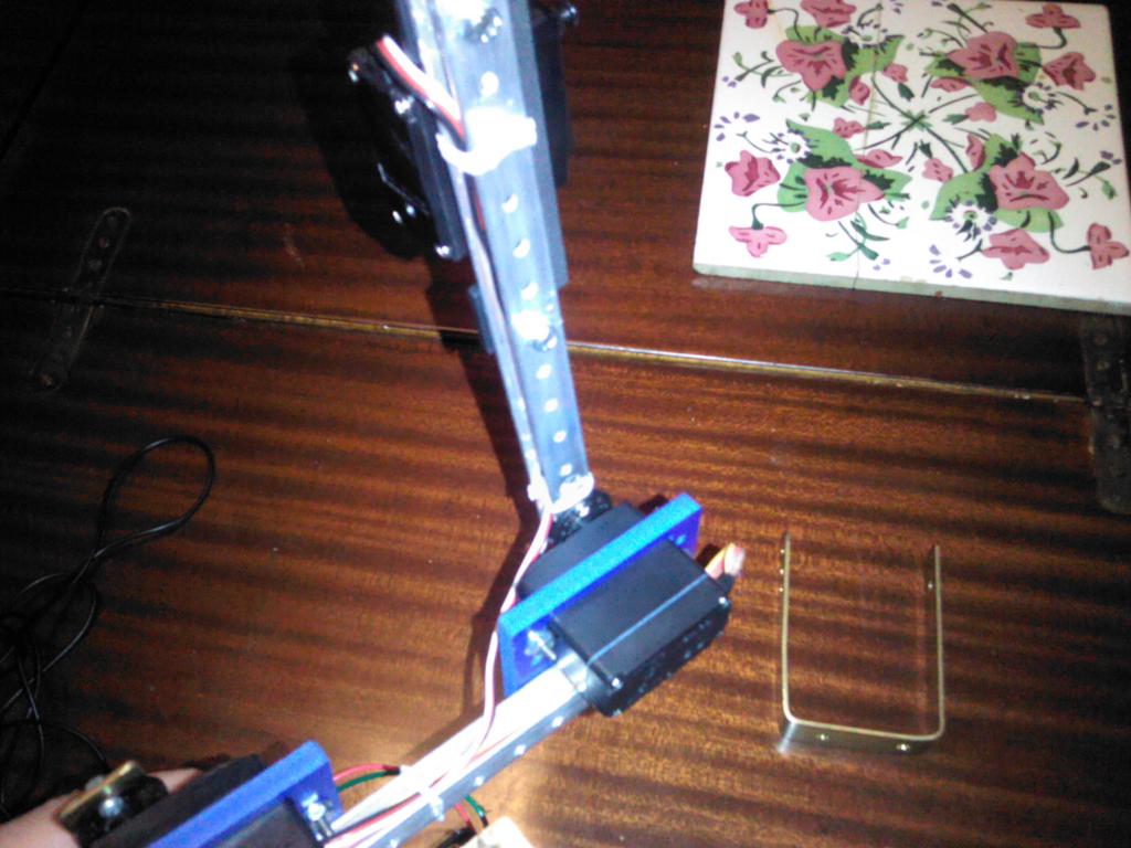
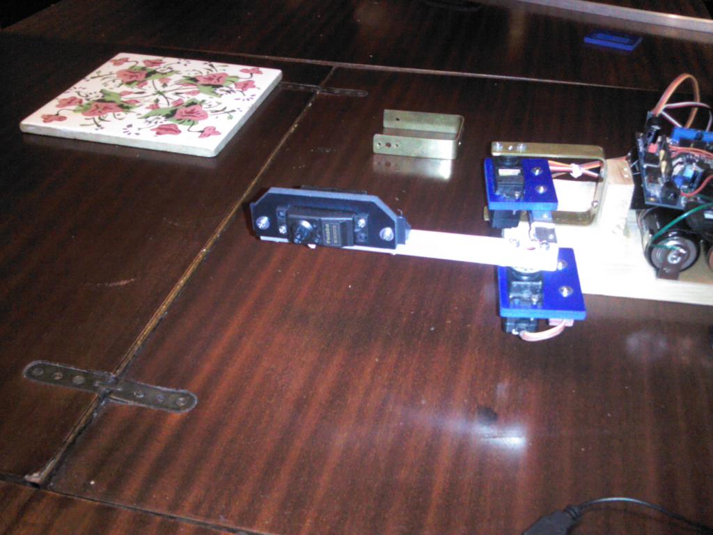
7. Mount the third servo at the end of the arm perpendicular to the other two. This servo will be used for the end effector lift mechanism. It will be best to use a lighter servo here to keep the mass lower.
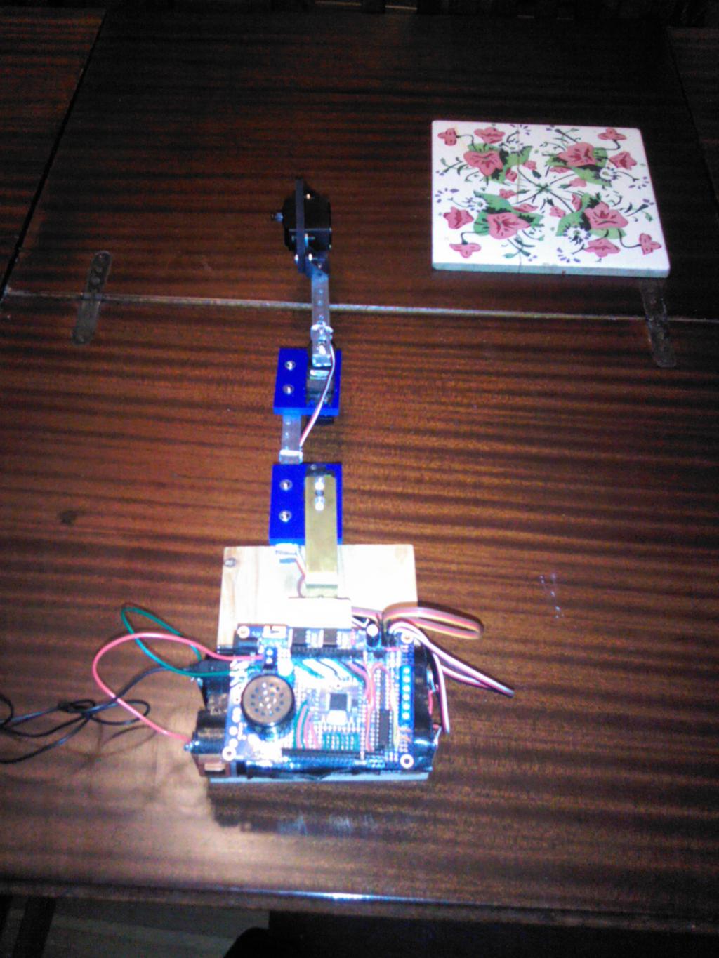
8. Mount the battery hold on the base and the control board above it. You'll need at least 3 servo headers, but the project board has four, so it will do nicely. Using D sized batteries allows the arm to fully extend without falling over as seen below.
This forms the basic structure of the arm and I now plan to finish up the IK code. I already have some C++ and Spin IK code from prior projects, so if anyone is interested in building one of these but doesn't want to deal with FORTH I can post that too.
I had planned to wait until I completed this project before writing it up, but I decided documenting as I go will help keep me motiviated. If anyone else is interested in building one feel free to ask questions. Any suggestions (particularly about the end effector) would be welcome too. Here's the bill of materials:
3 standard sized servos and horns. I'm using Power HD metal gear servos. ($10-$19)
1/4 inch ID aluminum U channel ($6)
three sets of servo brackets. I'm using sintra brackets from budget robotics ($2)
4-40 5/8 " bolts, nuts, and washers. ($3)
A block of scrap wood to mount it on.
Some metal to make a shoulder bracket ($2)
Battery holder for 4 D batteries. This was free as it was salvage. I'm using D batteries to add weight to the base, and power it.
A Propeller project board ($20).
Again this is a much simplier build than a revolute arm. Here's what I've done so far:
1. Cut two 7" pieces of U channel and drill 4-40 size holes every 1/2" to allow for experimentation with mounting.
2. On the first piece of U channel mount two servos using servo brackets. Here's a picture:
3. On the second piece of U channel enlarge a hole to allow access to a servo spline screw.
4. Make or buy a bracket to create a yoke for the shoulder joint. I make my own and glue a screw to the bottom of the servo to create the idler pivot. You can see the bracket in the first picture and the mounting below.
5. Screw the bracket to the wooden base, screw the servo horn to the bracket, and mount the servo bottom pivot. Use your strongest servo for this joint as it will be bearing the largest load.
6. Screw the second piece of U channel to the second servo horn.
7. Mount the third servo at the end of the arm perpendicular to the other two. This servo will be used for the end effector lift mechanism. It will be best to use a lighter servo here to keep the mass lower.
8. Mount the battery hold on the base and the control board above it. You'll need at least 3 servo headers, but the project board has four, so it will do nicely. Using D sized batteries allows the arm to fully extend without falling over as seen below.
This forms the basic structure of the arm and I now plan to finish up the IK code. I already have some C++ and Spin IK code from prior projects, so if anyone is interested in building one of these but doesn't want to deal with FORTH I can post that too.
Comments
http://www.ebay.com/itm/Random-One-Tower-of-Hanoi-Wood-Puzzle-Toy-Great-Brain-Teaser-Game-Puzzles-NEW-/331011538090?pt=Pretend_Play_Preschool_US&hash=item4d11d33caa
For anyone who's curious, below is the Propforth IK code debugged up to the set_position method.
\ Note: The goal is to write code that is as portable as possible. \ So I'll define gforth compatibility words to avoid using PropForth-isms : cells 4 * ; : -rot rot rot ; : ! L! ; : @ L@ ; \ arithmetic shift right n i bits \ ( n i -- n ) : asr/ dup 0> if \ while i > 0 shift right. 0 do 2/ loop else drop then ; hex \ Change radix in a portable manner. \ begin of fixed point trig functions. \ Values for common angles in brad13 0016 constant DEGREE_ANGLE 0400 constant EIGHTH_ANGLE 0800 constant RIGHT_ANGLE 1000 constant STRAIGHT_ANGLE \ sin function using brads ( brad13 -- sin32 ) \ The sine table contains one quadrant, so we'll need to \ work around that when generating the index into the table. \ note use um* with the return value! : sin dup \ save a copy of input for later. dup RIGHT_ANGLE and if \ ranges from 800 to 001 negate FFF and else \ ranges from 000 to 7FF 7FF and then \ convert to word count and index into sin table 2* E000 + W@ \ bit shift to 32 bits for future um* F lshift \ use the sign from the preserved value. swap STRAIGHT_ANGLE and if negate then ; decimal \ cos defined in terms of sin by coordinate rotation. : cos RIGHT_ANGLE + sin ; \ tangent can be derived from sine / cos. Both sine and cos are \ fast table lookups, so this is only a division more expensive \ than sine. \ ( brad13 -- tan ) : tan dup sin swap cos \ Note that we shift the cos down because we only want the \ numerator shifted left! 15 asr/ / ; \ compute asin via a binary search. \ Note: we're shifting angles up two bits to allow for greater \ precision during the search. It will be shifted back before return. \ ( sin - brad13 ) : asin \ push the first approximation and correction 0 EIGHTH_ANGLE 4* \ refine approximation and correction iteratively 13 0 do \ move the correction to the bottom of stack. -rot \ compare the sine of the approximation to the value. 2dup 2/ 2/ sin > if \ The approximation is too small, add the correction. rot dup -rot + else \ The approximation is too large, so decrease it. rot dup -rot - then \ half the correction factor for next iterration. swap 2/ loop \ return only the approximation. drop swap drop 2/ 2/ ; \ acos is defined in terms of asin \ ( cos -- brad13 ) : acos asin RIGHT_ANGLE - negate ; \ 13-bit fixed point four-quadrant arctangent. Given Cartesian vector (x, y), \ finds the angle subtended by the vector and the positive x-axis. \ y a signed integer \ x a signed integer \ ( y x -- brad13 ) : atan2 \ save x to use its sign to adjust results dup -rot \ form a fixed point y/x ratio from the inputs swap 15 lshift swap / \ push the first approximation and correction 0 EIGHTH_ANGLE 4* \ refine approximation and correction iteratively 13 0 do \ move the correction to the bottom of stack. -rot \ compare the sine of the approximation to the value. 2dup 2/ 2/ tan > if \ The approximation is too small, add the correction. rot dup -rot + else \ The approximation is too large, so decrease it. rot dup -rot - then \ half the correction factor for next iterration. swap 2/ loop \ return only the approximation. drop swap drop 2/ 2/ \ if x's sign was negative, then move results into 3 & 4 quadrants. swap 0< if STRAIGHT_ANGLE + then ; \ end of fixed point trig functions. \ begin of utility functions. \ Clamps n between max and min to prevent inverse trig function overflow \ ( n -- clamped_value ) : clamp RIGHT_ANGLE negate sin max RIGHT_ANGLE sin min ; \ Heater's Integer sqrt function : isqrtloop begin dup 0= if exit then swap over or swap -rot 2dup swap <= if swap over - swap rot swap over + else rot swap over - then 1 rshift swap 2 rshift 0 until ; \ Integer square root ( i -- s ) : isqrt 0 1 30 lshift isqrtloop drop swap drop ; \ squares the input ( i -- i*i ) : square dup * ; \ end utility functions \ begin inverse kinematics code 0 constant SHOULDER 1 constant ELBOW 2 constant WRIST 3 constant COUNT \ Size of robot bones in consistent units (mm recommended). variable humerus variable ulna variable humerus_sq variable ulna_sq \ Coordinate of pen tip in Cartesian space. variable x variable y \ Coordinates in arm scara polar space. variable shoulder_angle variable elbow_angle \ working variables during IK calculations variable s_w variable s_w_sqrt \ arrays to hold servo properties variable servo_center COUNT cells allot : servo_center() cells servo_center + ; variable servo_pin COUNT cells allot : servo_pin() cells servo_pin + ; \ Converts brads to a pulse with by using the ratio \ brads * steps / brads \ ( brads -- pulse width ) : brads_to_width 11000 * STRAIGHT_ANGLE / ; \ Computes the pulse width that matches the desired joint angle using \ the constraints of known angle to pulse values. Servo center is zero, \ counter clockwise a quarter circle is Pi/2, while clockwise is -Pi/2. \ angle - brad value \ index - servo index \ ( angle index -- ) : servo_position dup servo_pin() @ \ pin for servo swap servo_center() @ \ pulse width of center rot brads_to_width \ convert brad angle to pulse width + sm_setpos ; \ Used to initialize arm parameters. \ humerus - shoulder-to-elbow "bone" in mm \ ulna - elbow-to-wrist "bone" in mm : scara_arm \ (humerus ulna -- ) dup humerus ! square humerus_sq ! \ pre-calculations dup ulna ! square ulna_sq ! ; \ Sets the should angle member, computes the servo pulse width for that \ angle, and sets the associated servo. \ shoulder_angle - 32-bit floating point radian value \ ( shoulderAngleRads -- ) : set_shoulder \ Rotate the coordinate system by a right angle so that a straight angle \ is a full extension of the joint. RIGHT_ANGLE - dup shoulder_angle ! SHOULDER servo_position ; \ Sets elbow angle data member, computes the servo pulse width for that \ angle, and sets the associated servo. \ elbowAngle - floating point radian value \ ( elbowAngle -- ) : set_elbow \ Rotate the coordinate system by a right angle so that a straight angle \ is a full extension of the joint. RIGHT_ANGLE - negate dup elbow_angle ! ELBOW servo_position ; \ Park - Move the arm servos to the parked position. Called during start and \ stop. By parking the arm the servos will start from a known position and \ minimize startup lurch. \ ( -- ) : park RIGHT_ANGLE set_shoulder RIGHT_ANGLE set_elbow ; \ SetPosition : Arm positioning routine utilizing inverse kinematics. Since \ the arm is resting on a surface Z can only be positive. Servo movement \ constraints prevent y from being negative, But X can be a signed value. \ Note: This must be called before any of the move routines to initialize \ arm state! \ x - the side to side displacement. \ y - the distance out from the base center. \ ( x y -- ) : set_position \ Save the Cartesian space coordinates. y ! x ! \ Use Pythagorean theorem to calculate shoulder to wrist distance. x @ square y @ square + dup s_w ! isqrt s_w_sqrt ! \ s_w angle to centerline x @ y @ atan2 \ a1 is on the stack. \ s_w angle to humerus, note the need to prevent overflow! \ compute (_humerus_sq - ulna_sq + s_w) / (2 * humerus * s_w_sqrt) humerus_sq @ ulna_sq @ - s_w @ + 2 humerus @ * s_w_sqrt @ * / clamp acos \ a2 is on the stack \ shoulder angle = a1 + a2 + set_shoulder \ elbow angle \ compute ( humerus_sq + ulna_sq - s_w ) / ( 2 * humerus * ulna ) humerus_sq @ ulna_sq @ + s_w @ - 2 humerus @ * ulna @ * / clamp acos \ Set the elbow set_elbow ; \ Arm positioning routine utilizing inverse kinematics. Moves the arm from \ the current Y coordinate to the newY passed in. It maintains all other \ position state. \ newY - the new forward/back displacement \ ( newY -- ) : set_y x @ swap set_position ; \ Arm positioning routine utilizing inverse kinematics. Moves the arm from \ the current X coordinate to the newX passed in. It maintains all other \ position state. \ newX - the new height above the table \ ( newX -- ) : set_x y @ set_position ; \ Assign the pins to the joint 0 SHOULDER servo_pin() ! 1 ELBOW servo_pin() ! 2 WRIST servo_pin() ! \ Assign the centers of each joint. 4300 SHOULDER servo_center() ! 6700 ELBOW servo_center() ! 5000 WRIST servo_center() ! \ Arm dimensions( mm ) 132 \ shoulder-to-elbow "bone" 3.7" 142 \ elbow-to-wrist "bone" 3.1" scara_arm park sm_start_servos\ Note: The goal is to write code that is as portable as possible. \ So I'll define gforth compatibility words to avoid using PropForth-isms : cells 4 * ; : -rot rot rot ; : ! L! ; : @ L@ ; \ arithmetic shift right n i bits \ ( n i -- n ) : asr/ dup 0> if \ while i > 0 shift right. 0 do 2/ loop else drop then ; hex \ Change radix in a portable manner. \ begin of fixed point trig functions. \ Values for common angles in brad13 0016 constant DEGREE_ANGLE 0400 constant EIGHTH_ANGLE 0800 constant RIGHT_ANGLE 1000 constant STRAIGHT_ANGLE \ sin function using brads ( brad13 -- sin32 ) \ The sine table contains one quadrant, so we'll need to \ work around that when generating the index into the table. \ note use um* with the return value! : sin dup \ save a copy of input for later. dup RIGHT_ANGLE and if \ ranges from 800 to 001 negate FFF and else \ ranges from 000 to 7FF 7FF and then \ convert to word count and index into sin table 2* E000 + W@ \ bit shift to 32 bits for future um* F lshift \ use the sign from the preserved value. swap STRAIGHT_ANGLE and if negate then ; decimal \ cos defined in terms of sin by coordinate rotation. : cos RIGHT_ANGLE + sin ; \ tangent can be derived from sine / cos. Both sine and cos are \ fast table lookups, so this is only a division more expensive \ than sine. \ ( brad13 -- tan ) : tan dup sin swap cos \ Note that we shift the cos down because we only want the \ numerator shifted left! 15 asr/ / ; RIGHT_ANGLE sin constant MAX_SIN RIGHT_ANGLE negate sin constant MIN_SIN \ clamps n between max and min to prevent inverse trig function overflow \ ( n -- clamped_value ) : clamp MIN_SIN max MAX_SIN min ; \ compute asin via a binary search. \ Note: we're shifting angles up two bits to allow for greater \ precision during the search. It will be shifted back before return. \ ( sin - brad13 ) : asin clamp \ push the first approximation and correction 0 EIGHTH_ANGLE 4* \ refine approximation and correction iteratively 13 0 do \ move the correction to the bottom of stack. -rot \ compare the sine of the approximation to the value. 2dup 2/ 2/ sin > if \ The approximation is too small, add the correction. rot dup -rot + else \ The approximation is too large, so decrease it. rot dup -rot - then \ half the correction factor for next iterration. swap 2/ loop \ return only the approximation. drop swap drop 2/ 2/ ; \ acos is defined in terms of asin \ ( cos -- brad13 ) : acos asin RIGHT_ANGLE - negate ; \ 13-bit fixed point four-quadrant arctangent. Given Cartesian vector (x, y), \ finds the angle subtended by the vector and the positive x-axis. \ y a signed integer \ x a signed integer \ ( y x -- brad13 ) : atan2 \ Handle crossing x axis case dup 0= if drop RIGHT_ANGLE swap \ adjust sign based upon y's sign. 0< if negate then exit then \ save x to use its sign to adjust results dup -rot swap 15 lshift swap / \ push the first approximation and correction 0 EIGHTH_ANGLE 4* \ refine approximation and correction iteratively 13 0 do \ move the correction to the bottom of stack. -rot \ compare the sine of the approximation to the value. 2dup 2/ 2/ tan > if \ The approximation is too small, add the correction. rot dup -rot + else \ The approximation is too large, so decrease it. rot dup -rot - then \ half the correction factor for next iterration. swap 2/ loop \ return only the approximation. drop swap drop 2/ 2/ \ if x's sign was negative, then move results into 3 & 4 quadrants. swap 0< if STRAIGHT_ANGLE + then ; \ end of fixed point trig functions. \ begin of utility functions. \ Heater's Integer sqrt function : isqrtloop begin dup 0= if exit then swap over or swap -rot 2dup swap <= if swap over - swap rot swap over + else rot swap over - then 1 rshift swap 2 rshift 0 until ; \ Integer square root ( i -- s ) : isqrt 0 1 30 lshift isqrtloop drop swap drop ; \ squares the input ( i -- i*i ) : square dup * ; \ forms a bit shifted ratio for fixed point trig \ note the shift 15 and 2/, that's to avoid shifting \ into the sign bit. \ ( numerator denominator -- ratio ) : fixedPointRatio swap 15 lshift swap 2/ / 15 lshift ; \ end utility functions \ begin inverse kinematics code 0 constant SHOULDER 1 constant ELBOW 2 constant WRIST 3 constant COUNT \ Size of robot bones in consistent units (mm recommended). variable humerus variable ulna variable humerus_sq variable ulna_sq \ Coordinate of pen tip in Cartesian space. variable x variable y \ Coordinates in arm scara polar space. variable shoulder_angle variable elbow_angle \ working variables during IK calculations variable s_w variable s_w_sqrt \ arrays to hold servo properties variable servo_center COUNT cells allot : servo_center() cells servo_center + ; variable servo_pin COUNT cells allot : servo_pin() cells servo_pin + ; \ Converts brads to a pulse with by using the ratio \ brads * steps / brads \ ( brads -- pulse width ) : brads_to_width 11000 * STRAIGHT_ANGLE / ; \ Computes the pulse width that matches the desired joint angle using \ the constraints of known angle to pulse values. Servo center is zero, \ counter clockwise a quarter circle is Pi/2, while clockwise is -Pi/2. \ angle - brad value \ index - servo index \ ( angle index -- ) : servo_position dup servo_pin() @ \ pin for servo swap servo_center() @ \ pulse width of center rot brads_to_width \ convert brad angle to pulse width + sm_setpos ; \ Used to initialize arm parameters. \ humerus - shoulder-to-elbow "bone" in mm \ ulna - elbow-to-wrist "bone" in mm : scara_arm \ (humerus ulna -- ) \ pre-calculations dup ulna ! square ulna_sq ! dup humerus ! square humerus_sq ! ; \ Sets the should angle member, computes the servo pulse width for that \ angle, and sets the associated servo. \ shoulder_angle - 32-bit floating point radian value \ ( shoulderAngleRads -- ) : set_shoulder \ Rotate the coordinate system by a right angle so that a straight angle \ is a full extension of the joint. RIGHT_ANGLE - dup shoulder_angle ! SHOULDER servo_position ; \ Sets elbow angle data member, computes the servo pulse width for that \ angle, and sets the associated servo. \ elbowAngle - floating point radian value \ ( elbowAngle -- ) : set_elbow \ Rotate the coordinate system by a right angle so that a straight angle \ is a full extension of the joint. negate RIGHT_ANGLE + dup elbow_angle ! ELBOW servo_position ; \ Park - Move the arm servos to the parked position. Called during start and \ stop. By parking the arm the servos will start from a known position and \ minimize startup lurch. \ ( -- ) : park RIGHT_ANGLE set_shoulder RIGHT_ANGLE set_elbow ; \ calculates shoulder to waist distance using pythagoras' theorum. \ ( x y -- ) : pythagoras \ Save the Cartesian space coordinates. y ! x ! x @ square y @ square + dup s_w ! isqrt s_w_sqrt ! ; \ calculates shoulder angle using IK via fixed point trig. \ ( -- brad13 ) : ikshoulder \ s_w angle to centerline y @ x @ atan2 \ a1 is on the stack. \ s_w angle to humerus \ compute acos of (_humerus_sq - ulna_sq + s_w) / (2 * humerus * s_w_sqrt) humerus_sq @ ulna_sq @ - s_w @ + 2 humerus @ * s_w_sqrt @ * \ form a fixed point ratio of the numerator and denomenator fixedPointRatio \ use arccos to get a2 on the stack acos \ shoulder angle = a1 + a2 + ; \ calculates elbow angle using IK via fixed point trig. \ ( -- brad13 ) : ikelbow \ elbow angle \ compute acos of ( humerus_sq + ulna_sq - s_w ) / ( 2 * humerus * ulna ) humerus_sq @ ulna_sq @ + s_w @ - 2 humerus @ * ulna @ * \ form a fixed point ratio of the numerator and denomenator fixedPointRatio \ use arccos to get a2 on the stack acos ; \ SetPosition : Arm positioning routine utilizing inverse kinematics. Since \ the arm is resting on a surface Z can only be positive. Servo movement \ constraints prevent y from being negative, But X can be a signed value. \ Note: This must be called before any of the move routines to initialize \ arm state! \ x - the side to side displacement. \ y - the distance out from the base center. \ ( x y -- ) : set_position \ Save the Cartesian space coordinates and calculate s_w and s_w_sqrt pythagoras \ compute the shoulder angle ikshoulder set_shoulder \ Set the elbow ikelbow set_elbow ; \ Arm positioning routine utilizing inverse kinematics. Moves the arm from \ the current Y coordinate to the newY passed in. It maintains all other \ position state. \ newY - the new forward/back displacement \ ( newY -- ) : set_y x @ swap set_position ; \ Arm positioning routine utilizing inverse kinematics. Moves the arm from \ the current X coordinate to the newX passed in. It maintains all other \ position state. \ newX - the new height above the table \ ( newX -- ) : set_x y @ set_position ; \ Assign the pins to the joint 0 SHOULDER servo_pin() ! 1 ELBOW servo_pin() ! 2 WRIST servo_pin() ! \ Assign the centers of each joint. 4300 SHOULDER servo_center() ! 6700 ELBOW servo_center() ! 5000 WRIST servo_center() ! \ Arm dimensions( mm ) 132 \ shoulder-to-elbow "bone" 142 \ elbow-to-wrist "bone" scara_arm park sm_start_servos\ Note: The goal is to write code that is as portable as possible. \ So I'll define gforth compatibility words to avoid using PropForth-isms : cells 4 * ; : -rot rot rot ; : ! L! ; : @ L@ ; \ arithmetic shift right n i bits \ ( n i -- n ) : asr/ dup 0> if \ while i > 0 shift right. 0 do 2/ loop else drop then ; hex \ Change radix in a portable manner. \ begin of fixed point trig functions. \ Values for common angles in brad13 0016 constant DEGREE_ANGLE 0400 constant EIGHTH_ANGLE 0800 constant RIGHT_ANGLE 1000 constant STRAIGHT_ANGLE \ sin function using brads ( brad13 -- sin32 ) \ The sine table contains one quadrant, so we'll need to \ work around that when generating the index into the table. \ note use um* with the return value! : sin dup \ save a copy of input for later. dup RIGHT_ANGLE and if \ ranges from 800 to 001 negate FFF and else \ ranges from 000 to 7FF 7FF and then \ convert to word count and index into sin table 2* E000 + W@ \ bit shift to 32 bits for future um* F lshift \ use the sign from the preserved value. swap STRAIGHT_ANGLE and if negate then ; decimal \ cos defined in terms of sin by coordinate rotation. : cos RIGHT_ANGLE + sin ; \ tangent can be derived from sine / cos. Both sine and cos are \ fast table lookups, so this is only a division more expensive \ than sine. \ ( brad13 -- tan ) : tan dup sin swap cos \ Note that we shift the cos down because we only want the \ numerator shifted left! 15 asr/ / ; RIGHT_ANGLE sin constant MAX_SIN RIGHT_ANGLE negate sin constant MIN_SIN \ clamps n between max and min to prevent inverse trig function overflow \ ( n -- clamped_value ) : clamp MIN_SIN max MAX_SIN min ; \ compute asin via a binary search. \ Note: we're shifting angles up two bits to allow for greater \ precision during the search. It will be shifted back before return. \ ( sin - brad13 ) : asin clamp \ push the first approximation and correction 0 EIGHTH_ANGLE 4* \ refine approximation and correction iteratively 13 0 do \ move the correction to the bottom of stack. -rot \ compare the sine of the approximation to the value. 2dup 2/ 2/ sin > if \ The approximation is too small, add the correction. rot dup -rot + else \ The approximation is too large, so decrease it. rot dup -rot - then \ half the correction factor for next iterration. swap 2/ loop \ return only the approximation. drop swap drop 2/ 2/ ; \ acos is defined in terms of asin \ ( cos -- brad13 ) : acos asin RIGHT_ANGLE - negate ; \ 13-bit fixed point four-quadrant arctangent. Given Cartesian vector (x, y), \ finds the angle subtended by the vector and the positive x-axis. \ y a signed integer \ x a signed integer \ ( y x -- brad13 ) : atan2 \ Handle crossing x axis case dup 0= if drop RIGHT_ANGLE swap \ adjust sign based upon y's sign. 0< if negate then exit then \ save x to use its sign to adjust results dup -rot swap 15 lshift swap / \ push the first approximation and correction 0 EIGHTH_ANGLE 4* \ refine approximation and correction iteratively 13 0 do \ move the correction to the bottom of stack. -rot \ compare the sine of the approximation to the value. 2dup 2/ 2/ tan > if \ The approximation is too small, add the correction. rot dup -rot + else \ The approximation is too large, so decrease it. rot dup -rot - then \ half the correction factor for next iterration. swap 2/ loop \ return only the approximation. drop swap drop 2/ 2/ \ if x's sign was negative, then move results into 3 & 4 quadrants. swap 0< if STRAIGHT_ANGLE + then ; \ end of fixed point trig functions. \ begin of utility functions. \ Heater's Integer sqrt function : isqrtloop begin dup 0= if exit then swap over or swap -rot 2dup swap <= if swap over - swap rot swap over + else rot swap over - then 1 rshift swap 2 rshift 0 until ; \ Integer square root ( i -- s ) : isqrt 0 1 30 lshift isqrtloop drop swap drop ; \ squares the input ( i -- i*i ) : square dup * ; \ forms a bit shifted ratio for fixed point trig \ note the shift 15 and 2/, that's to avoid shifting \ into the sign bit. \ ( numerator denominator -- ratio ) : fixedPointRatio swap 15 lshift swap 2/ / 15 lshift ; \ end utility functions \ begin inverse kinematics code 0 constant SHOULDER 1 constant ELBOW 2 constant WRIST 3 constant COUNT \ Size of robot bones in consistent units (mm recommended). variable humerus variable ulna variable humerus_sq variable ulna_sq \ Coordinate of pen tip in Cartesian space. variable x variable y \ Coordinates in arm scara polar space. variable shoulder_angle variable elbow_angle variable wrist_angle \ working variables during IK calculations variable s_w variable s_w_sqrt \ arrays to hold servo properties variable servo_center COUNT cells allot : servo_center() cells servo_center + ; variable servo_pin COUNT cells allot : servo_pin() cells servo_pin + ; \ Converts brads to a pulse with by using the ratio \ brads * steps / brads \ ( brads -- pulse width ) : brads_to_width 11000 * STRAIGHT_ANGLE / ; \ Computes the pulse width that matches the desired joint angle using \ the constraints of known angle to pulse values. Servo center is zero, \ counter clockwise a quarter circle is Pi/2, while clockwise is -Pi/2. \ angle - brad value \ index - servo index \ ( angle index -- ) : servo_position dup servo_pin() @ \ pin for servo swap servo_center() @ \ pulse width of center rot brads_to_width \ convert brad angle to pulse width + sm_setpos ; \ Used to initialize arm parameters. \ humerus - shoulder-to-elbow "bone" in mm \ ulna - elbow-to-wrist "bone" in mm : scara_arm \ (humerus ulna -- ) \ pre-calculations dup ulna ! square ulna_sq ! dup humerus ! square humerus_sq ! ; \ Sets the should angle member, computes the servo pulse width for that \ angle, and sets the associated servo. \ shoulder_angle - 32-bit fixed point radian value \ ( shoulderAngleRads -- ) : set_shoulder \ Rotate the coordinate system by a right angle so that a straight angle \ is a full extension of the joint. RIGHT_ANGLE - dup shoulder_angle ! SHOULDER servo_position ; \ Sets elbow angle data member, computes the servo pulse width for that \ angle, and sets the associated servo. \ elbowAngle - fixed point radian value \ ( elbowAngle -- ) : set_elbow \ Rotate the coordinate system by a right angle so that a straight angle \ is a full extension of the joint. negate RIGHT_ANGLE + dup elbow_angle ! ELBOW servo_position ; \ Sets wrist angle data member, computes the servo pulse width for that \ angle, and sets the associated servo. \ wristAngle - fixed point radian value \ ( wristAngle -- ) : set_wrist dup wrist_angle ! WRIST servo_position ; \ calculates shoulder to wrist distance using pythagoras' theorum. \ ( x y -- ) : pythagoras \ Save the Cartesian space coordinates. y ! x ! x @ square y @ square + dup s_w ! isqrt s_w_sqrt ! ; \ calculates shoulder angle using IK via fixed point trig. \ ( -- brad13 ) : ikshoulder \ s_w angle to centerline y @ x @ atan2 \ a1 is on the stack. \ s_w angle to humerus \ compute acos of (_humerus_sq - ulna_sq + s_w) / (2 * humerus * s_w_sqrt) humerus_sq @ ulna_sq @ - s_w @ + 2 humerus @ * s_w_sqrt @ * \ form a fixed point ratio of the numerator and denomenator fixedPointRatio \ use arccos to get a2 on the stack acos \ shoulder angle = a1 + a2 + ; \ calculates elbow angle using IK via fixed point trig. \ ( -- brad13 ) : ikelbow \ elbow angle \ compute acos of ( humerus_sq + ulna_sq - s_w ) / ( 2 * humerus * ulna ) humerus_sq @ ulna_sq @ + s_w @ - 2 humerus @ * ulna @ * \ form a fixed point ratio of the numerator and denomenator fixedPointRatio \ use arccos to get a2 on the stack acos ; \ Arm positioning routine utilizing inverse kinematics. Since the \ arm is resting on a surface Z can only be positive. Servo movement \ constraints prevent y from being negative, But X can be a signed value. \ Note: This must be called before any of the move routines to initialize \ arm state! \ x - the side to side displacement. \ y - the distance out from the base center. \ ( x y -- ) : set_xy \ Save the Cartesian space coordinates and calculate s_w and s_w_sqrt pythagoras \ compute the shoulder angle ikshoulder set_shoulder \ Set the elbow ikelbow set_elbow ; \ Arm positioning routine utilizing inverse kinematics. Moves the arm from \ the current Y coordinate to the newY passed in. It maintains all other \ position state. \ newY - the new forward/back displacement \ ( newY -- ) : set_y x @ swap set_xy ; \ Arm positioning routine utilizing inverse kinematics. Moves the arm from \ the current X coordinate to the newX passed in. It maintains all other \ position state. \ newX - the new height above the table \ ( newX -- ) : set_x y @ set_xy ; \ returns the amount to adjust the index by \ ( finish start -- increment finish start ) : push_inc 2dup > if 1 else -1 then -rot ; \ uses the increment value to adjust value at TOS. \ ( increment finish current -- increment finish current+increment ) : do_inc rot dup >r -rot r> + ; \ a little pause to allow servos to settle : wait 10 delms ; \ smoothly moves X axis of arm from current position to new X passed in. \ ( newX -- ) : move_x \ get the current arm X x @ \ Get the step value on bottom of stack push_inc begin \ while new x and x are not equal 2dup = if 3drop exit then \ increment x do_inc \ move the arm dup set_x 15 delms 0 until ; \ smoothly moves Y axis of arm from current position to new Y passed in. \ ( newY -- ) : move_y \ get the current arm y y @ \ Get the step value on bottom of stack push_inc begin \ while new y and y are not equal 2dup = if 3drop exit then \ increment y do_inc \ move the arm dup set_y 15 delms 0 until ; \ computes a fixed point slope \ ( newX newY -- newX newY slope ) : get_slope 2dup \ ( newX newY newX newY ) y @ - \ ( newX newY newX deltaY ) swap x @ - \ ( newX newY deltaY deltaX ) \ we only care about y's sign as x is handled by caller abs \ compute the slope ratio swap 15 lshift swap / ; \ A fixed point y and slope to retain the fractional portions variable yfixed variable slope \ smoothly moves X and Y axis of arm from current position to newX and newY \ passed in. Useful for compound motion in the XY plane. \ ( newX newY -- ) : move_xy over x @ = if move_y drop else dup y @ = if drop move_x else get_slope slope ! \ newY has outlived its usefulness drop \ massage the stack to contain newX x x @ \ Get the step value on bottom of stack push_inc \ get current y and shift for fixed point arithmetic y @ 15 lshift yfixed ! \ move the arm from x to new x and y in steps of slope begin \ while new x and x are not equal 2dup = if 3drop exit then \ increment x and copy for set_xy do_inc dup \ add slope to y y shift, add, and store slope @ yfixed @ + dup yfixed ! \ place shift y and position arm 15 asr/ set_xy 15 delms 0 until then then ; \ Park - Move the arm servos to the parked position. Called during start and \ stop. By parking the arm the servos will start from a known position and \ minimize startup lurch. \ ( -- ) : park 50 50 set_xy 0 set_wrist ; \ Assign the pins to the joint 0 SHOULDER servo_pin() ! 1 ELBOW servo_pin() ! 2 WRIST servo_pin() ! \ Assign the centers of each joint. 4300 SHOULDER servo_center() ! 6700 ELBOW servo_center() ! 4550 WRIST servo_center() ! \ Arm dimensions( mm ) 132 \ shoulder-to-elbow "bone" 142 \ elbow-to-wrist "bone" scara_arm sm_start_servos park : demo 150 move_x 150 move_y 50 move_x 50 move_y 150 150 move_xy 50 move_x 150 50 move_xy 50 50 move_xy ;SinB/TanB=??? (see my 'Nerd Humor' post in General)
Here are some pictures of the completed end effector. The design turned out to be pretty simple after a number of more complicated failures. The rubber band seems to provide just enough give to prevent binding but still be effective.
Next is connecting the vacuum system to the suction cup and integration testing.