

S2 Scribbler Turtle goes Ultra-Violet & Infra-Red with 8x8 bit Graphics

Here i present a Modified S2 scribbler robot to draw graphics without the normal drawback of feint pencil lines or smudggy sharpie pens. (or lift your pen up workarounds)
The S2 trundles along plotting line for line its character payload...... basically where ever you tell it to go..... Yes it can be driven with LOGO (but that is another story soon to unfold)
I have replaced the pen slot with a bar of downward pointing UltraViolet LEDs one placed central to the hole and the others fanning out.....
This arrangement means that i can send the Propellers internal character-set (no costly data tables) to the UV array and plot to a Phosphorescent screen.
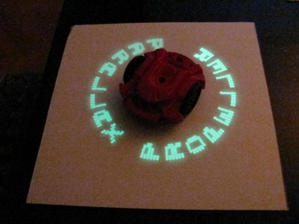
The S2 is tracking like a blood hound ..... I am well impressed by its XY coord system.
......and here it is in action .....

... i am currently upgrading the undercarriage to 16X UV Leds in the hope that it will be able to write some more exotic Ideograms .....or hopefully some Chinese..
The S2 trundles along plotting line for line its character payload...... basically where ever you tell it to go..... Yes it can be driven with LOGO (but that is another story soon to unfold)
I have replaced the pen slot with a bar of downward pointing UltraViolet LEDs one placed central to the hole and the others fanning out.....
This arrangement means that i can send the Propellers internal character-set (no costly data tables) to the UV array and plot to a Phosphorescent screen.
The S2 is tracking like a blood hound ..... I am well impressed by its XY coord system.
......and here it is in action .....
... i am currently upgrading the undercarriage to 16X UV Leds in the hope that it will be able to write some more exotic Ideograms .....or hopefully some Chinese..
Comments
Very impressive!
Gongratulation for the "project of the week"!!!!
My question about the creation of different size dots has to do with this:
I'm trying to scribble Einstain's portrait using my S2.
Using an Adobe photoshop filter I converse the initial image to an image with 4 sizes different dots.
Granting that you have the x-y coordinates of the center for every one of theese dots, as well as their size (a number between 1-4).
Can you create the portrait?
Thanks for the kind word.....and possible Challenge.......
I see no reason why this should not work..... needs a little "brain surgery" to wrap the coding up......
Indeed Yes the intensity of the UV can be controlled via PWM so more than 4 burn level diameter could be possible. (actually is possible from a previous project test)
The only tightness or stumbling block is that i would need a couple of passes with the 16 uv led rig i have below and bright glow time is limited to say..... 2 minutes (although it glow lingers much longer than this) , certainly enough time to take a mug shot photo.
Extra :-
The good news is my latest mod ..... is now using 16 x 3mm UV Leds .... instead of 5mm .. so i am able to pack more resolution (i am seriously toying with the idea of 30 leds.)
I designed and 3D printed this led carriage to make it easier to install under the tight undercarriage of the S2 .... it can found on my Thingiverse user page here
I like the idea of bitmap graphics and more so the vari-sized spots......
The S2 Hacker port has limited I/O, and I was wondering,
How are you driving the 16 LED's?, and what plan do you have to drive the 30 LED's?
Keep up the good fun.
-Tommy
Great execution & demo. I continue to be a fan of your great body of work. Now where do I buy my "Gareth Rocks" T-shirt?
The short and long is that the "HackerPort" is only a 6bit+2analog presentation.
Its a 5Volt interface (Yay and Booo...)
You cannot switch a(n) LED directly from the port because of the extra components (resistors) already attached to the port (input is fine .....output is a tad more complex.
So basically for the 8 bit version i used the 6 hackerport outputs P0-P5 and dexterously soldered 2 extra wires to the on-board propellerchip P6&P7 (and brought these out to a 2 pin header).
This mod does disable one of the IR front sensors (i actually de-soldered one leg of the IR affected (i think it was D3)......the plus is you gain 8 continuous bits....
This gives 8 bits P0-P7 and makes programming more linear ....
NOT forgetting that the hacker port P0-P5 is 5V logic and the Propeller mod P6&P7 is 3.3Volt logic.....Hmmmm
All these outputs are fed to a bank of transistors that drive the UV leds , meaning that i can adjust the current through each UV and even compensate for the 3.3V / 5V differences to get the LED intensity's equal.
I made a custom port connector which sits direct onto the HackerPort and the two extra P6P7 on flying lead to the propeller
Thats basically the 8 bit system
The 16Bit system is using 3mm UVleds
How the heck do you achieve a 16.....24......30 bank of UVLeds i hear you ask......... this is where i got you all wondering i guess.
Well tucked under the bonnet of the S2 i have installed an extra MDA propeller chip .....yes the S2 has a buddy doing all the work..
Basically i have a 2 way RXTX link between the two propellers and the Master "S2" sends the data string (POV character) to the Slave "MDA"
I did it this way because ....well its dead easy to add up to 30 Leds (ie 32bits minus 2bits for comms)
I can drive 16 leds directly this way (without transistors) however i am approaching the propellers max current IO constraints...so for 30 i will attach transistors.
I hope this answers your Questions.....?
You know i had a brain flash when i read your post........
.... what if i just sell Glow teeshirts and you can use the S2 setup to write "Erco - Rocks 2" directly onto it...... ;-)
What is the wavelength of the UV, and power rating of the LEDs?
(my leds are around 365 nm.... i think)
...the leds i bought were very inexpensive and i bought a 100 batch of "No.Name" ones....so i have no clue about the power ratings or the true wavelength..... all i did was too test 4 of them, one at 5mA , 10mA ,15mA & 20mA for 1 hour (they all lived and glowed the sheet well) so i guess you could even feed more current into them. at 5 to 10ma they are more than bright enough to leave a good impression on the phosphorscreen.
Your second approach with the extra MDA propeller chip is very interesting...!!!
Another question: the external dimension of a UV LED is like a normal LED?
And one suggestion-idea:
If you can drive Up to 30 Leds (e.g. 31 Leds), you could easily create 4 different size dots with the following LED arrangement:
I can't fully understand how you made the 2nd Propeller modification in your S2 robot .....So I can't make a test by my own ... But if you want to try the image creation with the different size dots using your S2 I'm willing to find the coordinates of an image and create the spin code for you. Of course you must give me the SPIN commands that turn on-off every Led.
Nikos
to answer your questions :-
.... a 5mm led is only 5mm on its body .....the bottom has the stupid surround ring which is 5.8mm (which i sand off for my system....to pack the leds closer together), and i would do the same for this system
Looking at your picture... yes it would be easy to construct a led matrix this way (3d print) ...
..interestingly i do notice that they are arranged in distinct lines ... another possibility would be to make a rig with two rows only ........
one row of 6 leds and one row of 5 interleaved leds below it ..
The S2 could blast 2 rows at a time move forward....then blast another 2 ...move forward another 2 ..forward ..and then the last single pair.
...however blasting the thing in one go appeals to me more ........31bits could be possible (a nightmare to debug though) if you go for the S2 transmit dot pattern with no handshake DTR/CTS type control..... Hmmmm
Basic data coding exchange is so :-
TX S2 :-
(CharLed is the 16bit led pattern)
PST.tx(CharLED) send direct to Slave (half is automatically truncated by tx command)
CharLED:=CharLED>>8 Shift the bits down 8 places
PST.tx(CharLED) send these to the Slave
RX Slave :-
RXDatain1 := PST.rx ; receive serial data 1st byte
RXDatain2 := PST.rx ; receive serial data 2nd byte
OUTA[0..7]:=RXDatain1 ; send to P0-P7 and light the leds
OUTA[8..15]:=RXDatain2 ; send to P8-P15 and light the leds
So basically i am only using the CharLED data packet and diplaying it using the OUTA[x..xx] command to pling the leds.....
I think that it is possiple to turn On-Off more than one Leds simultaniously using only one Pin. Isn't it?
If we can do it, then only 4 pins are enouph to control the entire Leds arrangment. I have the idea of the "Group" of Leds which acts like one single Led.
Let me explain:
We can also lift up and down the Led adapter like a pen using a servo on pin P0 (I suppose that the down movement makes the leds more efficient)
In this way you have a perfect "Brush" for the Chinese characters.
The advantage of this system is obvious: You don't have to do complicate programing in order to draw something. The x-y coordinates of the center of each dot and the size of the dot are enough!
Nikos
Yes indeed.... cool...... this will work...nice lateral thinking ..... just knocking up a 3D print prototype to hold the Leds......bear with me.....
... first calculation is the brush will turn out as 2cm wide using 3mm leds...... (-8 this could be almost in the right direction 8-)
I am not sure ....maybe only half the full circle needs to be made ....depends if the brush is "Always" in a forward direction (ie you don't need to use the trailing opposite leds)
..... however i will make a complete rig....for testing..
I decided to remove the inner "Fluff" to get a tighter fit for the leds......
You could make the S2 into a mobile typewriter..:thumb::thumb:
Cool stuff guys, keep up the good fun.
-Tommy
You have 32mm if you use 5 mm Leds.
If you use the 3mm Leds you will have a 20mm Led surface. (I think that 3mm Leds are preferable for this electronic UV Led Brush)
Does anyone know where can I order these 3mm UV Leds?
,,,,,,as well as the glowing paper?
Your Led adapter is very cool! Your 3d printer has done excellent job!
I have in mind a slightly different design.... But first I must find the UV Leds in order to measure dimensions with details!
If you propose any electric diagram and list of material with Leds and transistors It would be very Helpful!
All wired up ...... no driver transistors yet.... calculated the wire exit correctly......(High "5")
These are not full brightness as i have to regulate a constant current through each cluster.
If you squint your eyes you can just make out the 4 stages ...
Just need to attach the drivers and blast it with the S2s hacker port now......
Picture was taken in low light conditions ...exposure 2 seconds....
A M A Z I N G !!!!
I think it’s time to find the coordinates of Einstein’s portrait!
I’ll find the x-y coordinates of every dot, as well as the side of each dot, and I’ll write down into Excel file.
It will be a trying work but I believe that it is worth to do it.
The only I need at this stage is to give me the 4 sizes of your printed phosphorescent dots on the glowing paper's surface (as they appeared on your 1rst photo post#20)
Having these sizes I will be able to calculate the real coordinates and dimension of the final image, as well as the size of the glowing paper that we need.
(The image that will create the S2 will be much much bigger)
Keep the great work!
Nikos
I suggest i would be a good idea start with a smaller graphic.....Einstein will need a "Big" sheet from my calculations.....i mean very Big...
My Phosphor sheet is only 500mm square and mounted onto a 3mm high plastic protective backing (ie the S2 must stay at all times on the sheet , no room for wheels straddling over the edge, effective area 400x400mm)
Ok ....odd but true !!!! using 3mm leds yields :-
smallest 5mm
10mm
15mm
largest 20mm
seems the glow bleeds 1mm in all directions with just a 1 second burst of light.
BTW.... If you do plan to get some Phosphor vinyl then .....be careful with the supplier - some sell the "Good vinyl type" stuff and some will sell "Sprayed on stuff" which is a cheaper alternative (with very short glow time). I cant recommend a supplier as i bought mine a while back and they no longer stock it.
On my printed image (post#22) the largest dot has 2mm diameter.
Your phosphorescent largest dot has 20mm diameter. So the phosphorescent image will be 10 times bigger than the printed image.
As you can see from post #22 Enstein's portrait is 170mmX240mm.
So if you try to create the image using your S2 and your UV led Brush you will need a surface 1700mm X 2400mm at least!
It would be a spectacular achievment and a great attraction in a robotic exhibition!!!!
Maybe you have right. I must find a smaller image 40mm X 40mm for you (because you have 400mmX400mm printing area). If you have any preference feel free to send me!
However I don't give up from Einstein's portrait. I have already found some coordinates......
If Parallax could create a big board with the appropriate Phosphor sheet for demonstration in order to promote S2's abilities, I could sent them the code and of course you must sent them a UV led brush in order to create the portrait using the S2!
Nikos