

Fuzzy tail on RESET pulse from FT232R.
 Tracy Allen
Posts: 6,667
Tracy Allen
Posts: 6,667
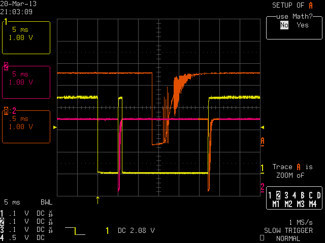
I've been troubleshooting a couple of Prop boards that from time to time would refuse to program, "prop not found". I am making a first excursion into including my own FT232R on the board, so I decided to start the troubleshooting there, thinking I might have a cold solder joint. I'd never looked closely at the reset signal on a 'scope before, and I was surprised to find a strong oscillation at ~10kHz as seen the first two attached screens. I'm using the circuit straight out of the prop-plug schematic, with a 0.01µF capacitor coupling the reset signal into the base of a '3904 type transistor, with 33kΩ to ground, collector to the Prop reset pin. All SMT within a fraction of an inch.
Scope:
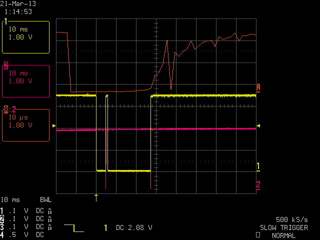
Yellow: Reset sequence from FT232R (This is from bst on a Mac, not sure if that makes a difference)
Pink: Reset output, collector of transistor.
Orange: time expansion of the pink trace, showing the oscillation.
Screen 1: one instance.
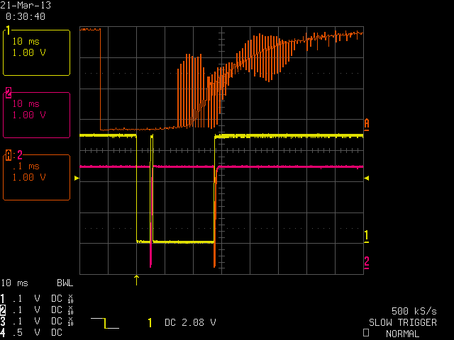
Screen 2: second instance, different time scale.
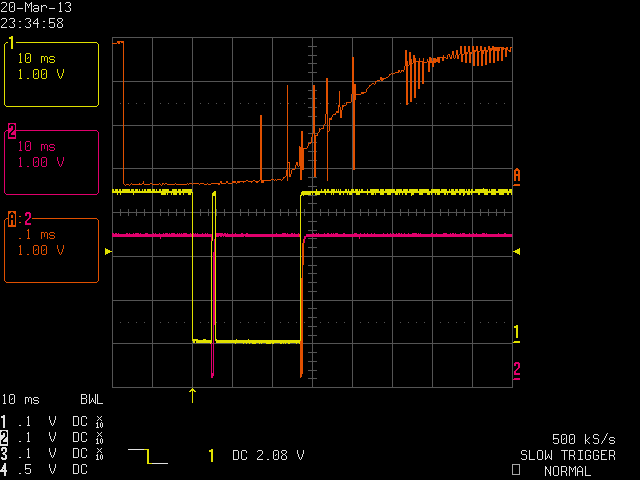
Screen 3: third instance, considerable variation with each reset.
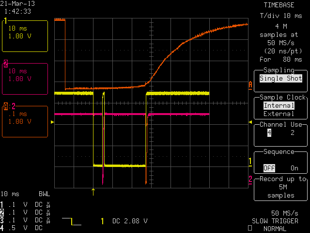
Screen 4: corrective measures taken (see below)
Screen 5: Taken from a different board, using the Prop Plug.
The corrective measure I took was first to try to degenerate feedback through the cb capacitance by putting a 200Ω resistor in series with the base, not much effect. Then tried a brute force 1nF capacitor from collector to emitter. That did the trick, screen 4, although there is still fuzz.
The final test is with a Prop Plug connected to program a different board. There is still oscillation, but observe the time scale. The reset pulse 1/10 as long as mine, so I hypothesize that the Prop Plug is using 1nF instead of 10nF. The oscillation is still ~10 kHz.
The boards with the above R & C fix now program okay, but like I said, the problem was intermittent.
My questions are:
Do you think the oscillation is a problem?
What would you do about it, if anything?
What component values do you use in that circuit.
Scope:
Yellow: Reset sequence from FT232R (This is from bst on a Mac, not sure if that makes a difference)
Pink: Reset output, collector of transistor.
Orange: time expansion of the pink trace, showing the oscillation.
Screen 1: one instance.
Screen 2: second instance, different time scale.
Screen 3: third instance, considerable variation with each reset.
Screen 4: corrective measures taken (see below)
Screen 5: Taken from a different board, using the Prop Plug.
The corrective measure I took was first to try to degenerate feedback through the cb capacitance by putting a 200Ω resistor in series with the base, not much effect. Then tried a brute force 1nF capacitor from collector to emitter. That did the trick, screen 4, although there is still fuzz.
The final test is with a Prop Plug connected to program a different board. There is still oscillation, but observe the time scale. The reset pulse 1/10 as long as mine, so I hypothesize that the Prop Plug is using 1nF instead of 10nF. The oscillation is still ~10 kHz.
The boards with the above R & C fix now program okay, but like I said, the problem was intermittent.
My questions are:
Do you think the oscillation is a problem?
What would you do about it, if anything?
What component values do you use in that circuit.
Comments
I would reflow all the solder joints and make sure there is no conductive path between the output from the transistor and the FT232 circuitry by cleaning the board thoroughly in that area and looking for possible shorts.
If you suspect a cold solder joint, look for one on nBOE. If it's not securely grounded, the Prop's internal pull-up on nRST could be flaking out on you. To test this theory further, you could add an external pull-up to nRST and see if the behavior changes.
-Phil
I've been looking around at component values people are using in that circuit. I see that the new Propeller Project Board uses 0.1µF, 10kΩ, 270Ω in series with the base, and a 2N3904. The 270Ω is new.
Kwinn, I'm not sure what you mean by "the reset pulse from the transistor is delayed slightly from the leading edge of the FT232 signal going low." The reset pulse is initiated when the FT232 signal goes high and pumps current into the base the xistor. On my 'scope traces, I have the zoomed view offset in time for clarity. I do need to check back in the circuit to be sure of the values and layout. Adding extra components made it pretty messy with flux but cleaned up the oscillation on the signal.
I toggled DTR by checking the checkbox in Parallax Serial Terminal to cause a high to low transition on resn.
My instinct is this 'oscillation' looks more like a measurement artifact, from an ADC that does not like slewing signals + any small noise.
This is most obvious in the second image.
I now use an smt transistor with internal 10k pulldown and 470R or 1k series in on the base, and an smt 10nf cap.
The double reset pulseislikely a mac issue but should not cause any problems.
Thanks for checking. Is the time scale on that 'scope trace 200µs per division? The schematic says the PDB uses 10 nF and 33k.
The Quickstart board (0.1µF/10k) never exhibits oscillation either, that I've seen while looking into this.
jmg, I don't see how the ADC (in the 'scope) has anything to do with it, as a measurement artifact. I see smooth transitions on some boards, sporadically or consistently oscillations on others. My initial thought was to blame feedback through the collector-base capacitance into a low-impedance base circuit, which is a known pathology of common emitter stages. The specific transistor & layout could make a difference.
The pic wiht only a single trace is 20 us / div
The dual trace with the bottom trace being a zoomed in version of the top trace
is 200 us/div for the top trace and 10 us/div for the zoomed bottom trace
Note the orange triangle shows the time reference of the zoomed out trace showing
the trigger point.
Tom
A misinterpretation of your waveform. I thought the left most high level was the reset pulse from the FT232 and the actual reset pulse was a glitch.
And, yes, I do have load problems with it: about half of them fail.
-Phil
I will have to go check my notes on the procedure of inserting a larger image.
Tom
It does not look like NPN oscillations, but what it could be (if you are confident it is not scope effects), is when the RST circuit 'fires' it connects the Cap to Vcc, and so you have during some portion of the decay time, a Transistor Linear amplifier, connected to Vcc - so you will amplify Vcc noise significantly.
I'd expect the Rbe to make that aperture very short, but if Rbe was very large, or open, then a slower rise and more Vcc effects would be seen.
Try reducing Rbe and see what happens. (& check if the cap really is 10nf ? )
Probably easier for someone to mess-up the C value than R value
Your rise-time seems to be much longer than the example in #13, so something is amiss.
I added more bypass capacitance to the Vccio+3V3OUT pin on the FT232. The suggested value is 0.1µF, which is what I had in there. Increasing it to 1µF substantially decreased the annoying fuzz.
The big effect though came from speeding up the pulse. It turned out that I had a 0.1µF in there along with 33kΩ. (To reiterate, that is what appears on many of the schematics) I changed that to 0.01µF and 10kΩ, and the result is very good. The pulse is conistently clean and a bit over 25µs in duration.
The values are what Cluso recommended, but not yet the series base resistor. The series base resistor seems like a good idea, otherwise the only series resistance limiting the peak current is the output resistance of the FT232 pin.
I will consider the problem by in large solved, but with a ?-mark by it to keep looking at it on different boards. Thanks for the help!
The Spice simulation does not need any inductance, it is simply an amplifier of the (in my example) 25mV of injected Vcc ripple.
The amplifier gain moves over time, it is lower just as it comes out of saturation, and then peaks, and decays again as the Vbe finally falls out of the linear region.
The power supply here comes from the USB port, and it is regulated down to 3.3V at the 3V3OUT pin of the FT232. That is the power supply that would have the fluctuations. The data sheet recommends a 100nF bypass there. That 3.3V is connected in my circuit and in others like the Prop Plug to the Vccio pin, which supplies the io to the Prop. It supplies current to the base of the reset transistor and also it supplies the txd signal drive and also maybe LEDs. The current allowed from 3V3OUT is 50mA -- it is a low power regulator. Suddenly attaching at 0.1 capacitor to that output by bringing DTR high should be quite a shock to a low-power linear regulator and might lead to the oscillations that are then amplified. That is a surmise. Increasing the bypass on 3V3OUT would improve the situation so long as the regulator remains stable with the larger bypass. Better is to decrease the shock by using 10nF instead of 100nF for the reset, And better yet, I am leaning toward agreement with Cluso, a digital transistor say 10k/10k into the base to avoid capacitor inrush altogether.
That gives a very clean reset pulse of a little over 15µs. Very easy on the FT232 output. Does anyone know of an official spec on the minimum reset pulse width for the Propeller? With the capacitor changed to 220pF, and a 4µs pulse width to the Prop, reset was still 100% okay.
I haven't that level of 'scopes to look at the pulses but it could explain what I was getting (in the end I went for a Hsync signal to start up on P16 to do the switch).
Alan
One thing I have noted is the use of low value series resistors to drive LEDs. On my FT232 board I use 3K3 (although 2x 3K3 drive 1 LED, so when both are on, the value is 1K65). The LED is to 5V, not 3V3, so I am not unnecessarily loading the 3v3 line anyways.
I just checked the Quickstart schematics. The 2x LEDs are joined and connected to 5V via 100R, so they are not loading the 3v3 of the FT232. Presuming a 2V LED drop, 3V/100R=30mA, though this would likely not be switching during the reset pulse. My led circuit (worst case) 3V/1K65=1.8mA.
I would not recommend a 10K/10K transistor. A 470R-1K series resistor to the base would be fine.
The transistor is driven into saturation (but not too much) and the pulse is clean 15µs and there is minimal load placed on the FT232 regulator.
With a light reset pullup, I would expect 10k/10k to work better than a lower Rb, as the higher values both reduce FT232 loading, and reduce the bandwidth during the brief time that the NPN device is in the linear region (via Cbc,Cbe) and also give some RFI and spike protection.
The only unanswered question, is what is MIN reset pulse of Prop ? (including margins)
I did find some useful info on BOD, but this did not cover RST pulse widths.
http://forums.parallax.com/showthread.php/116168-Brownout-reset-behavior-and-timing
In digital devices, Reset-release is usually CLK Sync'd to give best behaviour, but it may be latched prior to release.
Reset pins usually have ns region filters, to prevent spike events giving reset, or worse, a partial reset.
Some uC need (eg) 2 Clocks Min on reset, and some have a Async reset, at least as far as Port pins
It seems the default RC Osc period is ~ 74ns, & handles boot on RST release, so it may be that any start-up time for the RC Osc needs to be included.
I expected (without thinking about it too much) that a 10K series to the base would interact with the C to slow down the response and couls cause oscillation as it transitioned the trigger point. Clearly that did not happen.
Could you try a 10K pullup on the reset pin of the prop? I usually have a quad resistor pack on my pcbs connected to /Reset, SDA, SCL and sometimes WP (write protect of the eeprom to avoid inadvertant writing of the eeprom)
I would also add, does the RST pin have any hysteresis ?
Spice confirms 1n.10k/10k is much quieter than 10n/1k/1k, (10n/1k is not monotonic, in the test case, so would need hysteresis on the RST line)
and even 100p/100k/100k works, but Rise time moves to ~3.9us from ~1.5us @ 10k
470p/22k/22k has a rise time of 2.12us, for similar pulse width.
This is very close to the circuit we use in our products except we use a 10nF cap. The 10K resistor in series with the cap forms a pulse width discriminator which
helps filter out noise.
Of course, there are the usual windoze problems where the windoze drivers get locked, requiring an unplug and in some cases even a windoze restart. This even happens to my mouse ocaisonally - amazing what we learn to live with.
The reset signal comes in via a Schmitt trigger and goes to an asynchronous reset input on a flip-flop which traps the pulse and holds a 50ms release timer in reset. The pulse probably only needs to be 1 or 2 nanoseconds to register properly. At any rate, any low on the RESn pin gets stretched into a low-for-duration-plus-50ms pulse. After RESn goes high, the internal reset stays low for another ~50ms.
That reassures me that my 15µs pulse from the 1nF/10k/10k circuit and scope trace in post#23 is sufficient.
It does not explain the problem that led me into this in the first place, the annoying fact that these new boards of mine would sometimes refuse to program, "propeller not found", despite computer resets and the usual recourses. The cause may have been an unrelated, due to something that I missed, but since working on this I do feel much more comfortable with my reset circuit. The "not found" issue has not :thumb: (yet...) recurred with these boards.
When you had trouble reprogramming your boards, was there an old program running that was outputting serial data to P30? Although my sample size is small, and I don't have any hard data to back it yet, I've begun noticing a correlation between constant serial output on P30 and the sporadic "not found" syndrome.
-Phil
I don't think so, but I would by no means swear to it in court.
I do know what you mean. Most assuredly, streaming tx from the prop to the PC can interfere with re-programming the chip. It happens with bst on the Mac anyway--The entire ide slows down, menus, everything. I just made quick try as a refresher to see if I could make it happen, and instead it locked up my computer completely, even "force quit" was unresponsive. That's the way it goes sometimes.