

One sensor to discriminate Walsh-modulated IREDs
 Phil Pilgrim (PhiPi)
Posts: 23,514
Phil Pilgrim (PhiPi)
Posts: 23,514
Almost everyone here is aware of the advantages of modulated IREDs for rejection of background IR fluctuations and line-frequency noise from artificial lighting. Typically, the IRED modulation occurs at 38 kHz, to which the integrated detectors are tuned and respond with a digital output. But what if you wanted to respond to more than one IRED at a time and, moreover, know the intensity level of the response from each? Such a question is the theme of this thread.
First, we need to delve into Walsh functions. Walsh functions are the digital equivalent of the Fourier sine and cosine basis functions for decomposing waveforms into constituent parts. Unlike their sine and cosine counterparts, Walsh functions can take on only two values: -1 and +1. Like the Fourier sine and cosine basis functions, the Walsh basis functions are mutually orthogonal. This means that, over one full cycle, the product of any pair of these functions integrates to zero. Also, as with sine and cosine functions, the average duty cycle of Walsh functions (except for W(1, 1)) is 50%, a desirable characteristic for modulating IREDs with them.
By modulating a set of IREDs, each with a different Walsh function, and using a single analog IR detector, it should be possible to sort out which IREDs the return signal came from, along with how much each one contributed to the response. To this end, I purchased six IREDs from RadioShack and mounted them on a QuickStart board, as shown below:
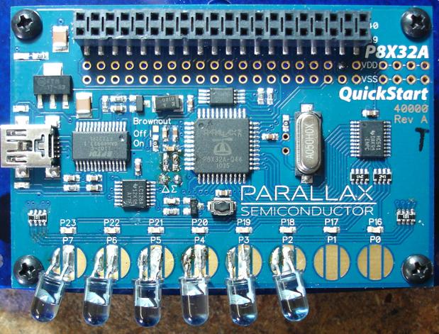
I replaced the 100K resistor packs in series with the touchpads with 100-ohm resistor packs, in order to drive the IREDs from the Propeller's P2-P7 pins.
For a sensor, I initially thought an IR phototransistor would work well with a sigma-delta input. Although phototransistors are notoriously slow, in the sigma-delta circuit VCE would be held constant at about Vdd / 2, thus eliminating any slowness due to its Miller capacitance. Unfortunately, even in this circuit, the phototransistor was too slow for detecting modulated signals accurately.
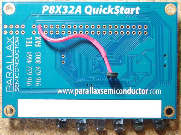
In the end, I purchased an AMS (TAOS) TSL262R-LF, which converts incoming IR to a voltage output and has a very fast response (at the expense of sensitivity). I mounted the sensor to the bottom of the board so as to avoid direct illumination form the rear of the IREDs:
The output of the sensor (powered from 3.3V) is fed into a DC-coupled sigma-delta ADC, populated on the QuickStart board using SMD resistors and caps. Here's a block diagram:
Each IRED is modulated with a different Walsh function, as shown above. With strong reflections coming from all six Walsh-modulated IREDs, here's what the output from the sensor looks like:
Now for some Propeller counter magic! The feedback output from the sigma-delta counter is combined XOR fashion with the outputs to the IREDs in six different counters, spanning three cogs. Remember that the feedback is a pulse train whose duty cycle is inversely proportional to the signal coming into the input pin. So when the input pin is predominantly high (i.e. the output duty cycle is low) and an IRED pin is high, the XOR counter will add to phsx. The same happens when both the input and IRED output are predominantly low. In other words, the XOR counter for any particular IRED is correlating the input signal from the sensor with the Walsh function driving the associated IRED to tell how much that IRED is contributing to it. Because the Walsh functions are orthogonal, the contributions from the other five signals will, ideally, sum to zero. The result is that each counter demodulates the signal only from its associated IRED.
In the attached program, the IREDs are modulated at 950 Hz (i.e. 1.053 ms for each of the 16 increments in a full Walsh waveform cycle). Each counter is sampled every eight full cycles, with the result of each sample poked into an array. These results can be displayed via the serial output, and they are also used to drive the blue LEDs on the QuickStart board with intensity proportional to the log of the response from each IRED. Here's a video that shows the result:
[video=vimeo;62453123]
Some practical applications of this technique might include crude robotic "vision", where obstacles can be roughly located in the field of view and their distances approximated via the return signal strength. Another app might be a light curtain that uses Walsh modulation instead of physical baffling to isolate the different channels. In any event, it scratched an itch for me, wondering if it would actually work. Apparently, it does!
-Phil
First, we need to delve into Walsh functions. Walsh functions are the digital equivalent of the Fourier sine and cosine basis functions for decomposing waveforms into constituent parts. Unlike their sine and cosine counterparts, Walsh functions can take on only two values: -1 and +1. Like the Fourier sine and cosine basis functions, the Walsh basis functions are mutually orthogonal. This means that, over one full cycle, the product of any pair of these functions integrates to zero. Also, as with sine and cosine functions, the average duty cycle of Walsh functions (except for W(1, 1)) is 50%, a desirable characteristic for modulating IREDs with them.
By modulating a set of IREDs, each with a different Walsh function, and using a single analog IR detector, it should be possible to sort out which IREDs the return signal came from, along with how much each one contributed to the response. To this end, I purchased six IREDs from RadioShack and mounted them on a QuickStart board, as shown below:
I replaced the 100K resistor packs in series with the touchpads with 100-ohm resistor packs, in order to drive the IREDs from the Propeller's P2-P7 pins.
For a sensor, I initially thought an IR phototransistor would work well with a sigma-delta input. Although phototransistors are notoriously slow, in the sigma-delta circuit VCE would be held constant at about Vdd / 2, thus eliminating any slowness due to its Miller capacitance. Unfortunately, even in this circuit, the phototransistor was too slow for detecting modulated signals accurately.
In the end, I purchased an AMS (TAOS) TSL262R-LF, which converts incoming IR to a voltage output and has a very fast response (at the expense of sensitivity). I mounted the sensor to the bottom of the board so as to avoid direct illumination form the rear of the IREDs:
The output of the sensor (powered from 3.3V) is fed into a DC-coupled sigma-delta ADC, populated on the QuickStart board using SMD resistors and caps. Here's a block diagram:
Each IRED is modulated with a different Walsh function, as shown above. With strong reflections coming from all six Walsh-modulated IREDs, here's what the output from the sensor looks like:
Now for some Propeller counter magic! The feedback output from the sigma-delta counter is combined XOR fashion with the outputs to the IREDs in six different counters, spanning three cogs. Remember that the feedback is a pulse train whose duty cycle is inversely proportional to the signal coming into the input pin. So when the input pin is predominantly high (i.e. the output duty cycle is low) and an IRED pin is high, the XOR counter will add to phsx. The same happens when both the input and IRED output are predominantly low. In other words, the XOR counter for any particular IRED is correlating the input signal from the sensor with the Walsh function driving the associated IRED to tell how much that IRED is contributing to it. Because the Walsh functions are orthogonal, the contributions from the other five signals will, ideally, sum to zero. The result is that each counter demodulates the signal only from its associated IRED.
In the attached program, the IREDs are modulated at 950 Hz (i.e. 1.053 ms for each of the 16 increments in a full Walsh waveform cycle). Each counter is sampled every eight full cycles, with the result of each sample poked into an array. These results can be displayed via the serial output, and they are also used to drive the blue LEDs on the QuickStart board with intensity proportional to the log of the response from each IRED. Here's a video that shows the result:
[video=vimeo;62453123]
Some practical applications of this technique might include crude robotic "vision", where obstacles can be roughly located in the field of view and their distances approximated via the return signal strength. Another app might be a light curtain that uses Walsh modulation instead of physical baffling to isolate the different channels. In any event, it scratched an itch for me, wondering if it would actually work. Apparently, it does!
-Phil
Comments
Any reason for doing it that way rather than using the 40 pin header phil?
Ah I get it because of the resistor pack you replaced
Or as Kramer would say, http://www.youtube.com/watch?v=6CAT4gPzIg8&feature=player_detailpage#t=50s
And to further rub our faces into it, he does it all with a mere QuickStart board and parts from Radio Shack. Geez!
Over in the robotics forum I've built several compound eyes using IR LED's coupled with 38khz receivers or phototransistors. When I use the 38khz receiver I use a frequency sweeping technique to determine rough distance coupled with zone sweeping to pinpoint the position of obstacles. I can usually do all that for four zones with a single cog.
Here you are outputting different frequencies to the zones, but I think at the same time. So while I'm using time to separate my zones, you are using the frequencies of the Walsh functions?
Update : I read it again and I see how the counters are separating you zones.
I like to look at origins of ideas, before they get wrapped up in formalisms. The Wolfram page said these functions had been used by "electrical engineers such as Frank Fowle in the 1890s to find transpositions of wires that minimized crosstalk" so I thought maybe there is something there that would, ring a bell. A search for Frank Fowle reveals that he was the editor of the 1920 edition of the Standard Handbook for Electrical Engineers. Oh, drat, not on my bookshelf.
My interest in Walsh functions dates back to the '70s where there was some vague relationship among them, genetic algorithms, and Gray coding. But the details are too fuzzy at this point in time to recount, except that I remembered them as digital, orthogonal basis functions, and that recollection stuck. The Wolfram link was the best I could find via Google on short notice to explain them further to those who might be unfamiliar with them. It wasn't my starting point, however.
Truth be known, there are probably better basis functions out there for this app. One problem with Walsh functions is that the phase-shifted versions appear not to be orthogonal with each other. This manifests itself in information "leakage" when the detector is slow to respond. Ideally, a set of basis functions for this app would not only be orthogonal, but "left and right orthogonal." IOW, if you shift the phase one period left or right, between any two basis functions, orthogonality would still be preserved.
That's why a detector with a fast response became so critical and also why I limited the fundamental frequency to 950 Hz. Any faster and even the 7 usec delay from the TSL262R resulted in spillage into the other demodulators, resulting in crosstalk between channels. CDMA RF transmission suffers the same issues, BTW. To demodulate CDMA, three detectors are used: one centered on-phase, one leading, and one trailing. These are used jointly as a phase detector to lock onto the pseudo-random data pattern. Fortunately, in this app, the phase is already known. So a fast detector is all that's necessary to maintain a "lock" on the signal.
I had thought of using another IRED as the detector in the photodiode circuit you've shown. But I did not have any 100+ meg resistors lying about for the feedback.
-Phil
Boxcar Function, Cal, Fast Walsh Transform, Hadamard Matrix, Heaviside Step Function, Rectangle Function, Sal, Sequency, Square Wave, Walsh Transform, Hadamard matrix, ceiling function, Thue-Morse sequence ,orthogonal, matrix product , "sequency".....
Sadly......... I'm not....:frown:
Dave
One 16 bit string for each of the 6 LEDs, played back repeatedly in parallel at the fixed period per bit. Pick one string and XOR it with itself or one of the others, writing + when there is a match of bits and - when there is no match. For example, here is the first one with itself:
1010010101011010
1010101010101010
++++++++++++++++
16 +'s of course. Averages out in the detector to a maximum positive value. Or, if the detection is weak, there are errors and you get an indication of distance.
Now the first sequence with the second one:
1010010101011010
1010101010101010
++++
++++
Averages to zero. And the first with the third:
1010010101011010
1001011010010110
++--++----++--++
same, averages to zero. And the fifth sequence with the sixth:
1100001100111100
1001100101100110
+-+--+-++-+--+-+
Again. That is what it means for the signals to be orthogonal.
Could we use the same algorithm with some ultrasonic transducers?
Graham
For returns with a phase delay, you could modulate the ultrasonic carriers with three different audio frequencies and use an I/Q mixer to demodulate the return signal, followed by FIR filters to select each audio channel.
-Phil
Graham
FWIW, Digikey has values up to 50GΩ in stock in SMT 0805 or 1206.
Your TSL262R gain is 2.8V/µA, followed by a sigma-delta gain of x1. An ordinary photodiode (area comparable to the TSL262R, 1mm2?) might work with 3MΩ feedback directly in the sigma-delta to give those signal levels. Are your 'scope signals coming from a tap off of the feedback pin?
I pressed my Ohmmeter probes to the leads in the photo you posted but got 120 megs. That's close enough, though. Thanks!
"Are your 'scope signals coming from a tap off of the feedback pin?"
No, directly from the sensor (i.e. on the sensor side of the series 100K).
-Phil
Maybe a system more resistant to phase delays would be to sample the delta-sigma at the modulation frequency and demodulate each channel in software? That way delays less than one modulation "bit" period could be hidden? (I think this would need an ADC with a sample and hold circuit.) I bet this could all be done in one cog as an added bonus.
Lawson
-Phil
-Phil
http://dangerousprototypes.com/2013/04/07/parallax-propeller-discriminates-walsh-modulated-ireds/
-Phil