

First Magnetic Encoder PCB Attempts
 Duane Degn
Posts: 10,588
Duane Degn
Posts: 10,588
A couple of months ago, forum member, Kirk Fraser offered to pay me to write an object to interface a Propeller with AustriaMicroSystems AS5055 magnetic encoder chip.
It was a fun job. I posted my progress of writing the code in this thread.
As I learned to use the sensors, I became impressed by them.
I had been wanting to learn to use DipTrace for a while so I thought I'd try making some PCBs for this chip.
I had used Eagle a little, but at the suggestion of someone here at Parallax, I switched to DipTrace. I'm very glad I did. It didn't take long for me to know how to use DipTrace better than I did Eagle (I didn't know how to use Eagle very well).
Anxious to get a PCB made, I submitted this board to BatchPCB as soon as I had DipTrace figured out enough to make a footprint for the chip (I've since learned where to find the various footprints in DipTrace) and lay some traces.
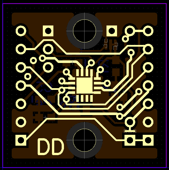
I didn't submit the silkscreen layers because I couldn't get the silkscreen items to behave the way I wanted. I've got a little better with the silkscreen but I still can't turn off the patterns' silkscreen component (for example the box around a set of headers).
I sent the above board in on May 2. I think I still have another week or two before I'll receive it.
The above board can use any of the AS5055 communication modes including the 4-wire SPI daisy-chain mode. The above board could be daisy-chained by having the incoming wires connect to the left side of the board and the outgoing connect to the right side.
The holes that aren't on either the far left or far right of the board are for jumpers used to configure the chip.
One application I hope to use this chip for is as an encoder on continuous rotation servos.
A lot of the servos I've converted have potentiometers 1/2" in diameter. I wondered if I could design a PCB with one of these sensors small enough to fit in the 1/2" spot left by the pot.
For my first attempt, I used the sensor in 3-wire, read only mode. I tried to see how many would fit on a 5cm x 5cm board that Itead Studio uses.
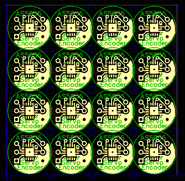
After seeing 16 PCBs fit on one of the 5cm x 5cm boards, I realized the price of the PCB itself wasn't very much with such a small board. A 4-layer board costs more, but a PCB of 0.25 square inches wouldn't cost much per board.
With 4-layers, I was able to add the extra lines needed for 4-wire daisy-chain mode.
The center 1/2" circle could be cut out and it would have the same functionality as the larger board. The pins not inside the center circle are there to make it easier to make connections with the board.
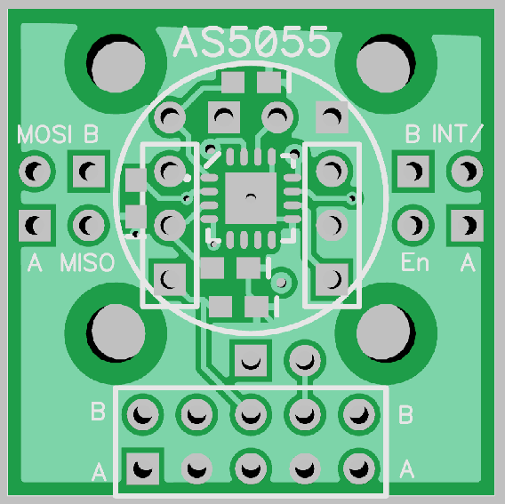
A 2x5 header could be used to connect with a 10-wire ribbon cable. A 10-wire ribbon cable would allow many of these sensors to be easily daisy-chained together.
Because of the need for one boards MISO pin to be connected to the next board's MOSI pin, one of the wires on the 10-wire ribbon cable would need to be cut between each board. The wire cut would need to alternate from one board to the next. A pair of jumpers would need to be set on each board to connect the MOSI and MISO pins to the appropriate wire.
The chip also includes an interrupt pin and an enable interrupt pin that would also require alternating cut wires. There's a second pair of jumpers for connection these pins.
There are other modes these chips can be used in that don't require cut wires. I included pins and jumpers to allow the chip to be used in any of its possible modes.
I included places for the caps and resistor recommended when using long wires with SPI communication. I placed the non-essential capacitors on the top with the sensor. If the extra caps aren't needed, then the top of the board will be flat to make mounting the magnet hardware easier.
I've noticed much of the space of these boards is taken up by the various header pins. I wondered if using 2mm pitched pins would save space on a board and make it easier to make these sensor boards small.
Here's my attempt using 2mm spaced holes.
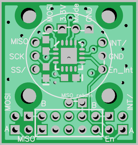
The 2mm hardware didn't help as much as I had hoped. One problem with the 2mm spaced holes is there is barely enough room for a trace to fit between the pins. I had to reduce the ring size around the holes in order to fit the traces safely between them. I'm not sure if I'll have this board made or not. I'll probably get a few made just to see if the 2mm hardware has any advantages I haven't thought of yet.
While the SPI protocol for these chips isn't very complicated, I think it might be hard for a Basic Stamp to interface with these chips.
I was hoping to find a way to make these sensors a bit more user friendly. One idea was to use a microcontroller with the chip so the sensor could then just send its data as asynchronous serial.
An ATtiny2313 has a built in UART but as very limited program memory. I decided to try using an ATtiny84 with this sensor and bit bang a serial driver for it.
(I had tried to fit the smallest Propeller package on a 1/2" diameter PCB, but I just could not get it to fit with the encoder chip, voltage regulator and EEPROM.)
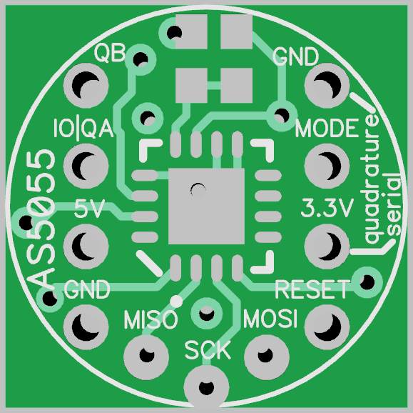
Here's my attempt at a smart sensor board.
Front of the board.
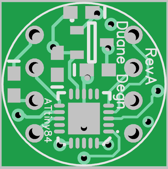
Back of the board.
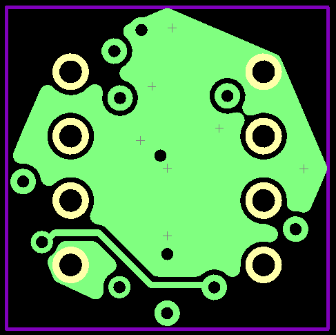
Top inner layer (with ground plane).
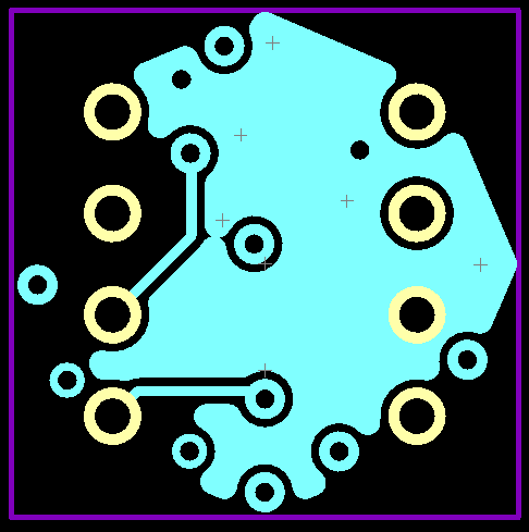
Bottom inner layer (with 3.3V plane).
I haven't figured out how to make a round board edge or a round copper pour.
I included a 3.3V regulator so the board could use the servo's power supply. One additional wire would be required to use the sensor with a microcontroller.
I included a jumper on this board so the user could decide if they wanted to use the board in serial mode or as in quadrature encoder mode.
The quadrature encoder mode would translate the position data into simulated quadrature encoder pulses. This way someone already setup to receive quadrature encoder information wouldn't have to change there program much when using these sensors.
I haven't figured out how many pulses per second an ATtiny84 could transmit yet. I plan to make the number of pulses sent per revolution configurable. I haven't worked on the software for this yet. I plan to work on the software while I wait for these boards to be made.
I'll likely make one other version of of PCB with this sensor. It will include the last board shown but with mounting holes and a place from additional headers that aren't so close to the sensor.
Now for some questions.
Do any of you see any problems with my last board (last four pictures)?
Any suggestions on other configurations of these sensors?
How do I make a round circuit board with DipTrace? How about a round copper pour?
Any suggestions on a PCB house to use? Itead Studios look like they have pretty good prices but they take 20 days of so to deliver the boards.
Kirk suggested PCBCart. I think they may be more expensive, but they also deliver a lot faster (I think in around 8 days).
I know with Itead Studios, it costs less if I submit multiple boards together and cut them apart myself. I'm not sure what the best (least expensive) method of submitting boards to PCBCart would be.
Thanks for looking and reading.
It was a fun job. I posted my progress of writing the code in this thread.
As I learned to use the sensors, I became impressed by them.
I had been wanting to learn to use DipTrace for a while so I thought I'd try making some PCBs for this chip.
I had used Eagle a little, but at the suggestion of someone here at Parallax, I switched to DipTrace. I'm very glad I did. It didn't take long for me to know how to use DipTrace better than I did Eagle (I didn't know how to use Eagle very well).
Anxious to get a PCB made, I submitted this board to BatchPCB as soon as I had DipTrace figured out enough to make a footprint for the chip (I've since learned where to find the various footprints in DipTrace) and lay some traces.
I didn't submit the silkscreen layers because I couldn't get the silkscreen items to behave the way I wanted. I've got a little better with the silkscreen but I still can't turn off the patterns' silkscreen component (for example the box around a set of headers).
I sent the above board in on May 2. I think I still have another week or two before I'll receive it.
The above board can use any of the AS5055 communication modes including the 4-wire SPI daisy-chain mode. The above board could be daisy-chained by having the incoming wires connect to the left side of the board and the outgoing connect to the right side.
The holes that aren't on either the far left or far right of the board are for jumpers used to configure the chip.
One application I hope to use this chip for is as an encoder on continuous rotation servos.
A lot of the servos I've converted have potentiometers 1/2" in diameter. I wondered if I could design a PCB with one of these sensors small enough to fit in the 1/2" spot left by the pot.
For my first attempt, I used the sensor in 3-wire, read only mode. I tried to see how many would fit on a 5cm x 5cm board that Itead Studio uses.
After seeing 16 PCBs fit on one of the 5cm x 5cm boards, I realized the price of the PCB itself wasn't very much with such a small board. A 4-layer board costs more, but a PCB of 0.25 square inches wouldn't cost much per board.
With 4-layers, I was able to add the extra lines needed for 4-wire daisy-chain mode.
The center 1/2" circle could be cut out and it would have the same functionality as the larger board. The pins not inside the center circle are there to make it easier to make connections with the board.
A 2x5 header could be used to connect with a 10-wire ribbon cable. A 10-wire ribbon cable would allow many of these sensors to be easily daisy-chained together.
Because of the need for one boards MISO pin to be connected to the next board's MOSI pin, one of the wires on the 10-wire ribbon cable would need to be cut between each board. The wire cut would need to alternate from one board to the next. A pair of jumpers would need to be set on each board to connect the MOSI and MISO pins to the appropriate wire.
The chip also includes an interrupt pin and an enable interrupt pin that would also require alternating cut wires. There's a second pair of jumpers for connection these pins.
There are other modes these chips can be used in that don't require cut wires. I included pins and jumpers to allow the chip to be used in any of its possible modes.
I included places for the caps and resistor recommended when using long wires with SPI communication. I placed the non-essential capacitors on the top with the sensor. If the extra caps aren't needed, then the top of the board will be flat to make mounting the magnet hardware easier.
I've noticed much of the space of these boards is taken up by the various header pins. I wondered if using 2mm pitched pins would save space on a board and make it easier to make these sensor boards small.
Here's my attempt using 2mm spaced holes.
The 2mm hardware didn't help as much as I had hoped. One problem with the 2mm spaced holes is there is barely enough room for a trace to fit between the pins. I had to reduce the ring size around the holes in order to fit the traces safely between them. I'm not sure if I'll have this board made or not. I'll probably get a few made just to see if the 2mm hardware has any advantages I haven't thought of yet.
While the SPI protocol for these chips isn't very complicated, I think it might be hard for a Basic Stamp to interface with these chips.
I was hoping to find a way to make these sensors a bit more user friendly. One idea was to use a microcontroller with the chip so the sensor could then just send its data as asynchronous serial.
An ATtiny2313 has a built in UART but as very limited program memory. I decided to try using an ATtiny84 with this sensor and bit bang a serial driver for it.
(I had tried to fit the smallest Propeller package on a 1/2" diameter PCB, but I just could not get it to fit with the encoder chip, voltage regulator and EEPROM.)
Here's my attempt at a smart sensor board.
Front of the board.
Back of the board.
Top inner layer (with ground plane).
Bottom inner layer (with 3.3V plane).
I haven't figured out how to make a round board edge or a round copper pour.
I included a 3.3V regulator so the board could use the servo's power supply. One additional wire would be required to use the sensor with a microcontroller.
I included a jumper on this board so the user could decide if they wanted to use the board in serial mode or as in quadrature encoder mode.
The quadrature encoder mode would translate the position data into simulated quadrature encoder pulses. This way someone already setup to receive quadrature encoder information wouldn't have to change there program much when using these sensors.
I haven't figured out how many pulses per second an ATtiny84 could transmit yet. I plan to make the number of pulses sent per revolution configurable. I haven't worked on the software for this yet. I plan to work on the software while I wait for these boards to be made.
I'll likely make one other version of of PCB with this sensor. It will include the last board shown but with mounting holes and a place from additional headers that aren't so close to the sensor.
Now for some questions.
Do any of you see any problems with my last board (last four pictures)?
Any suggestions on other configurations of these sensors?
How do I make a round circuit board with DipTrace? How about a round copper pour?
Any suggestions on a PCB house to use? Itead Studios look like they have pretty good prices but they take 20 days of so to deliver the boards.
Kirk suggested PCBCart. I think they may be more expensive, but they also deliver a lot faster (I think in around 8 days).
I know with Itead Studios, it costs less if I submit multiple boards together and cut them apart myself. I'm not sure what the best (least expensive) method of submitting boards to PCBCart would be.
Thanks for looking and reading.
Comments
If you want to make round circuit boards in DipTrace...
Select the "place board outline" button, left click to start the outline, then right click and select "Arc Mode".
Drag and drop your new round shape, It takes some practice, but it's easy enough..
-Tommy
That worked great.
Edit (8/16/13): Add information about an early PCB attempt. I sent this PCB to another forum member. I don't know if they ever populated the board or not (I don't think they did). If any of you have one of these early boards, let me know and I'll replace it with a more recent version.
The above shows the top of the board. I've labeled the pins. I intended to use this board in a chain of sensors. Unfortunately I placed the pins for the INT/ and INT_EN/ on the wrong edge of the board. In order to use a board the way I had originally intended would require eight pins on each edge. The interrupt signal should have its own return patch similar to the data return path.
To use the board as a stand alone board the interrupt enable pin needs to be connected to ground through the jumper or the header pin. The board's "wire_mode" pin is hard wired to 4-wire SPI mode. The board could still be used in 3-wire mode by connection the MOSI pin to VDD. The wire_mode pin only needs to be set to the 3-wire configuration if MISO and MOSI are tied together and commands and readings from the sensor are alternately sent and received. Receive only 3-wire SPI works with the wire_mode pin configured to 4-wire mode and MOSI pin tied to VDD.
The diagram above shows capacitor and resistor numbers which may be placed on the bottom of the circuit board. One resistor and most of the capacitors where added in order to increase the range of the SPI signal. The resistor and capacitor values may be found in the ams appnote on the topic (I don't recall the values off hand).
R1 and C2 were added to match the ams demo board. These components are only needed if VDD and VDDp are not identical. R1 on the demo board was 15 ohms, however since VDD and VDD are the save the pads for the R1 may be shorted together.
C2 on the demo board is 4.7uF but this capacitor may be left off.
C1 is the only capacitor required on the board. It should be 0.1uF.
To summarize, only C1 needs to be populated with a 0.1uF capacitor. An 0 ohm jumper resistor, Wire or a solder blob may be used for R1 and R2.
The various pins should be connected to the Propeller (or other 3.3V microcontroller) as shown in the AS5055 datasheet or AS5055 Adapter Operation Manual.
Again, I don't recommend these boards be used.
Would Tony Stark use it in field conditions?
That would be for a slow moving wheel (BOE-Bot speed). I don't think the ATtiny84 could output 4,096 PPR if the wheel were turning fast.
The ATtiny84 (84 from now on) will need to read the sensor's value with SPI and then figure out how many pulses to send on the two quadrature encoder lines. Once it has sent the pulses, it would then take another reading from the sensor and repeat.
Some of the limiting factors will be how quickly the 84 can read the sensor and send pulses and how quickly the host uC can read pulses.
My hope is it will make it easy to add a very accurate encoder to a drive wheel of a robot.
I'll likely dig my Basic Stamps out of storage to see how many PPR the BS2 can handle. Or better yet, ask you! What would be a good PPR setting for these when using them with a BS2?
I think using a serial link with the sensor would probably be a more efficient way to use these with a BS2. The BS2 could send a request for position (and possibly speed) and the sensor would send back either an absolute position or a differential position from the last position request. The type of information sent from the encoder will hopefully be configurable to make it easier for the host uC to use the data.
A big unknown in all of this is how much the little 84 uC can do. I don't have much experience programming this chip so I'm not sure what it's capable of.
I started designing a version with mounting holes. This is my current design.
Ideally the magnet would be mounted at the center of the wheel. One way to mount a magnet on a CR servo would be to mount the magnet on a shaft extending from the final gear of the servo. With the encoder located where the pot had previously been, the magnet would be ideally located for measuring rotation.
I'm hoping there would be other options of mounting magnet and encoder that wouldn't require the opening of a servo case. If a magnet were mounted at the center of a wheel and the encoder mounted over it, it should also give accurate rotation information.
I haven't tested it on a wheel yet, but I have tried circling a magnet around the sensor. This off axis method also gave rotation information. So hopefully as long as a magnet can be mounted relatively close to the center of a wheel, these sensors should be able to measure its position.
Now this is the hope. Since these encoders don't require any physical contact with the magnet to work, they don't have any mechanical parts to wear out. They should also work if they get wet or dirty.
I don't think they will help much in creating a new element. You need a big laser to do that.
BTW, I still like PhiPi's magnetic encoder using flexible fridge magnet material.
Now I see what's been keeping you away from the Oval Office challenge!
How about an oval circuit board, at least...?
The sensor is $5.04 when purchased 100 at a time. One at a time, they're $6.68.
The ATtiny84 costs $1.8764, 25 at a time (you've got to love those fractional cents).
Well ya, what's not to like? Phil keeps coming up with amazing things. I try to look at it as "inspiring" rather than "intimidating" (though I'm not always successful).
Yes, this, and "because the guys on the forum told me to" does work as well as a reason to be doing something as I thought it would.
Thanks to Tommy, I could do that.
Front of board with magnetic encoder.
Back of board with MCP1700 voltage regulator and ATtiny84.
The mounting holes should be large enough for 4-40 hardware. The board is 0.95" square. The center of the mounting holes are spaced 0.75" (edit: 0.70") from each other. The guts of the board are still within the center 1/2" circle. I'm doubt I'll make many (if any) of these boards since if I'm going to use this size of a board, I probably don't need it to be 4-layers.
I'm still hoping for feedback on the size of the boards and the position of the pins and mounting holes.
Are there better names for the pins? I'm using "IO|QA" for the asynchronous serial or channel A of the quadrature signal and "QB" for the quadrature B channel. I'm not thrilled with these names but I can't think of better names for the pins.
I'm not sure how difficult it will be to solder these small smt chips to both sides of a board.
One way I figure I could do it would be to solder the first chip with lead free solder and then solder the second chip with lead solder. Hopefully heating the board to melt the lead solder wont cause the lead free solder to melt (which may cause the first chip to fall off).
Edit (5/17/12): I replaced the above pictures the corrected versions. The original pictures are still attached to this post for reference purposes.
I can use the most tiny boards all the way around but if I were to use the larger boards, I'd request the centers be at 0.70" to easily fit in pre-punched perf boards drilled out for 4-40 screws, but it really doesn't matter since in production I'd be making holes with a CNC anyway. Making the soldering easy to automate should therefore be a higher priority.
The design of competitor www.Renishaw.com product is attractive, except for the price.
https://mail-attachment.googleusercontent.com/attachment/?ui=2&ik=cc633fdab9&view=att&th=136425e6fe6ff5e3&attid=0.1&disp=inline&realattid=3b2e5f8ab0553503_0.1&safe=1&zw&saduie=AG9B_P95rQ6FSearW0miqTKWSCas&sadet=1337238322322&sads=GsJFh8FHFZNy5KLloFqfCyrfeGg&sadssc=1
Kirk, I was mistaken about the distance of the holes. They are 0.70" apart and not 0.75".
I was hoping to keep all the pins on a 0.1" grid but the ISP header just wouldn't fit without making the board larger. The ISP would only be used for programming the ATtiny84 chip so normally it wouldn't be populated with header pins.
One would only use the ISP to upgrade firmware on the ATtiny84. I plan to program the chips myself before sending the boards out so the end user shouldn't need to use these connections.
I just noticed an error on the ISP. I have the ground and 3.3V pins swapped. I'll fix this before making any boards. (Edit: I've fixed the error and updated the pictures.)
Awesome job on the board layout! Looks great. It looks like that Diptrace program works well for designing the boards and I'll have to look into that as a replacement for the obsolete CircuitMaker/TraxMaker tool that I had been using.
Robert
Thanks Robert.
I like DipTrace. As I mentioned earlier, I used to use Eagle a little. I never had a board made with any of the PCBs I designed with Eagle (I hadn't designed many). I think DipTrace is more intuitive than Eagle and it didn't take long for my DipTrace knowledge to surpass my Eagle knowledge.
The free version of DipTrace limits the number of pins in a project and also limits the board to 2-layers. I purchased the upgrade so I could use 4-layers. I also needed to upgrade since the free version isn't supposed to be used for commercial endeavors.
I forget who started the thread about DipTrace, but it was a Parallax employee. I'm really glad they suggested it or I'd still be struggling with Eagle.
Great board! I am very interested in the AM chips, my present hang up is the diametric magnet and its mounting. I do not have the machine tools to build the mounts. What is your latest progress on that front?
Jim
This is my most sophisticated mount yet.
I used a drill press to make a hole in the end of a nylon 5M bolt and press fit the magnet.
I have a small hobby lathe which I hope use to make some other mounts.
Once I have these boards sent off to a board house, I plan to work on the software (for the ATtiny84) and I also plan to experiment with ways of mounting magnets with these sensors.
One think I want to find out is if I can get by with square (cubed) magnets.
While a nice 6mm diametrically magnetized round magnet is ideal for these encoders, they also work with non-ideal magnets.
I've used this setup with the encoders.
The above magnets are pretty inexpensive and sensor read the rotation of the magnet. The problem with using a non-ideal magnet is the output is likely to be non-linear as the magnet is rotated above the sensor. I didn't notice any obvious difference the in the output of the sensor using this magnet vs the 6mm magnet. I didn't quantify the rotation of the magnet/bolt to see if the readings from the sensor were in a linear relationship with the magnet's rotation so I don't know how it compares with the 6mm magnet (yet). One of the things I plan to test is how far from linear the readings using these various magnets are. I'm hoping the cube magnets will produce linear readings since I think the cube magnets would be relatively easy to mount and are seem to be less expensive than diametric round magnets.
If it is necessary to use non-ideal magnets, and the readings using these magnets are non-linear, then it should be possible to apply a correction algorithm with software so one could still obtain accurate rotation information with non-ideal magnets.
Using such an algorithm would likely reduce the precision of the encoder/magnet system at some angles, but I'm hoping sub-degree accuracy would still be possible.
I had previously attempted to fit a QFN Propeller on a 1/2" diameter PCB, but I just couldn't get all the parts to fit (with traces connecting them).
Most of the servos I've opened have a spot for a 1/2" pot under the final gear. The Futaba servos that came with my BOE-Bot originally had a smaller rectangular pot inside of it. Since I wouldn't be able to fit an encoder PCB in the little well previously occupied by the pot, I thought I'd try to make a board that would fit just below where the pot had originally been located.
The area inside the CR Futaba servo is about 16.2mm x 19.2mm. There's a little extra space along the sides of the motor, and the outside corners are occupied by the servos long screws so I didn't what to place any components in the two corners I'd need to notch in order to fit inside the servo.
This space was large enough to include a QFP (the smt chip with leads) Propeller on the PCB. I added a small TSOPP EEPROM and a MCP1700 regulator so it could use the servo's power source.
I added some mounting holes so it could be used other places besides just inside a servo. Of course the mounting holes would need to be cut off to us it inside a servo.
Here's the top with the AS5055 encoder chip, the voltage regulator, crystal and EEPROM.
Here's the bottom of the board with the Propeller.
I don't think it has all the decoupling caps I was hoping for, but I tried to squeeze caps in where ever I could.
I expected this to be a four layer board. I started laying traces using just two layers to see how far I could get before needing to add extra layers. I was surprised to find everything fitting. I did have to use P27's pad in order to get the EEPROM clock line to P28. Many of the Props pins aren't broken out. Besides the connections to the encoder chip, EEPROM and Prop Plug, I did break an additional four pins out to pads. This all fit on two layers.
I figure I'll use P30 and P31 for serial communication with the Prop and I may use the four free pad/pins to control the servo's H-bridge (maybe).
I just thought it would be interesting to have a Propeller inside a servo. Hopefully it will be one smart servo.
I welcome comments and critiques.
The PCBs are 0.5" in diameter. They include pads for an optional 3.3V regulator so they can be powered from the 5V of a servo. The PCB is small enough to fit inside a hobby servo where the potentiometer would normally be located.
Below shows the two sides of the PCB (top populated).
The pads for the optional 3.3V regulator are on the bottom of the PCB. There are also pads for three capacitors. If the regulator isn't use, only one capacitor is populated.
The photo below shows a PCB with the bottom of the board populated.
I planning to power this board from the servo's power supply. I'll use this board in 3-wire mode so three additional wires will be needed to control the servo.
The PCB below is wired for 4-wire mode and can be daisy chained with other encoders. This particular board has been tested and works correctly.
As RS_Jim has suggested, the real trick is going to be mounting the magnet. I'm still far from figuring out how to do this. The photo below shows the remains of one of the servo potentiometers. The board with the resistive traces shows how the original pot was the same diameter as the encoder PCB. The pot's shaft and bushing are above the resistive traces. I was hoping I could glue a magnet to the original shaft but after removing the pot's brushes there isn't much of the shaft left to glue,
I'll likely take apart another potentiometer and see if I can glue a magnet to the section containing the brushes.
The above photo also show a 3mm machine screw with a magnet glued with J.B. Weld. I'm planning to thread the screw into the final gear (metal in this case) from below. I think the screw is short enough to allow room for the servo horn's screw which will be threaded in from above. If the screw method works, I'll need to come up with some sort of jig to hold the magnet centered and level as the J.B. Weld cures.
I was considering adding a small microcontroller to the PCB in order for it to convert the SPI signal into an asynchronous serial signal with an option of having it provide quadrature encoder output. Below is a picture of a PCB with an ATtiny84. One of the many problems with this design is the ATtiny chip is as hard to solder as the AS5055. Another problem is the ATtiny doesn't have an UART so the serial protocol would need to be bit banged. I don't know enough about AVR chips to know if I'd need an external crystal in order to have the chip provide asynchronous serial. I'll probably wait to continue the ATtiny board until I know more about the microcontroller.
I hope to test my J.B. Weld magnets in a servo today. I'll post the results after the test.
Good call Dr. erco.
I have been using Devcon Home two part epoxy from Home Depot , (or Lowes, can't remember), with very good results lately.
I can't imagine the metal particles would help. Any ferrous metal above the magnet weakens the magnetic field on the bottom of the magnet.
I think you're right. I'll want to use a different epoxy if I use this method to mount the magnet.
I did consider attaching a magnet to a nylon screw.
I used Polymorph to attach the magnet to the screw. I didn't like how the polymorph protruded beyond the magnet which would require a larger gap between magnet and sensor chip.
The nylon also doesn't thread into the final gear as easily as the stainless steel screws.
This is where I'd like the magnet to be mounted.
Up in the round pocket made for the potentiometer. My plan is to thread the screw into the final gear from below.
The screw turns relatively easily and I can use a second screw with magnet as a type of screw driver.
Below is the screw with magnet after is has been "screwed in".
There is still some room in the final gear to accept a screw to secure the servo horn.
Unfortunately the screw/magnet combo has a lot of wobble. I think I can overcome the wobble with a carbon fiber bushing. I added a layer of Polymorph to the screw to reduce the wobble inside the bushing.
I'll need to add some sort of LocTite to the threads in order to keep the screw from working itself loose (or too tight).
This particular method requires the servo to have metal gears. I'm still hoping of finding an alternative way to hold a magnet in the proper position which won't require metal gears.
I still haven't tried these encoders with a servo yet. I'm very curious if the motors will interfere with the encoders or not. I'm inclined to think they won't be much of a problem.
Who do you know that has a 3D printer? The magnet mount begs for a printed part! I would like to have a 60mm long "bolt" with the magnet at one end and the other end threaded for my wind direction sensor for my weather station. The board with the Propeller chip could run the entire WX station, mag encoder direct, 1 i/o for wind velocity, 1 i/o for rain gage, 4 for the barometer/temperature sensor, 2 for RTC (share with eeprom,). Send all collected data once per second using 30/31 connected to XBee ( update commands like clock set via Xbee).
Jim
What are the dimensions of the final-part in the last photo?
Jim
The black carbon fiber tube is 5mm in diameter. The part is currently bolted inside of the servo so I'm not sure how long of a piece of tubing I used. It looks like it's about 5mm long. The bolt is a 3mm x 16mm machine screw.
The machine screw requires a plastic disk be removed from the final servo gear.
It would be better if I could make a part to replace the original potentiometer. Here's another picture of the shaft and bushing (taken on a mirror).
The brass and aluminum piece in the last picture of post #16 is a brass rod 3.5 mm in diameter. The rod narrows as it passes through the aluminum bushing. The outside diameter of the bushing is 4.96mm. The 4.96mm diameter section is about 3mm high (including taper to brass rod).
The narrow section of the brass rod (which engages with the final gear) is 2mm wide in its smallest dimension. The flat section of the brass rod is 5mm long. The brass rod extends 7.1mm above the bushing.
The wide flange of the bushing is 8mm in diameter and about 0.5mm high.
The small piece of brass sticking through the bottom of the bushing is probably too small to glue anything to it. Maybe I could protect the bushing with some wax paper and attempt to glue a magnet directly to the brass but I'm doubtful it would work.
The piece which originally held the brushes of the pot is made from steel and would likely interfere with the sensor.
I may attempt finding someone to make a printed part but I still have several other ideas I'd like to try.
I have successfully installed a magnet and sensor inside the servo. I now need to write some software to use the sensor for position feedback (this will be the fun part (I mean funner part)).
I'm using the sensor in 3-wire mode without the interrupt pin. Since the PCB has its own 3.3V regulator the servo only has three additional wires from the additional sensor.
I'll post some video once I have the servo using the sensor for position feedback. My day job is getting in the way of my experiments this weekend so this is all taking longer than I had thought it would.
I made the pad to for the mode setting solder jumpers a little larger than my previous version. I also added pads for optional solder jumpers next to the MOSI pin and interrupt enable pins.
I've been busy working on the software side of these encoders. I've moved the filtering algorithm to the PASM portion of the code so it runs really fast now. 98.6% of the time the driver is waiting for the interrupt pin to go low. The sensor is being read at just over 2KHz.
I'm having trouble in my attempts to mount the encoder inside the servo. The readings are very erratic. I'm going to try using a board wired to use 4-wire SPI to see if behaves any better than the board wired for 3-wire mode. I'm concerned the magnets in the motor are interfering with the encoder. I'm going to be very disappointed if these won't work inside of a servo.
Thanks.
Hi Kirk,
I don't know how this post got past me without my seeing it sooner.
The short answer to the spot welding is no. One way for a magnet to loose its magnetic properties is by getting too hot. I'm not sure if a spot weld would complete destroy the magnetic properties of a magnet or not but I doubt it's would be a good way to attach a magnet to a shaft. I also think spot welding would damage the metal plating of the magnet.
I don't know if superglue or red thread lock is strong enough to hold a magnet in place. As you suggest, it probably depends on how well the surfaces meet. A cupped receptical would likely be more secure than just a flat surface. In the case of the machine screw I used, the screw actually curved away from the magnet.
The JB Weld seems to be holding the magnet reasonably well but I doubt I'll use JB Weld again. I think erco raised a valid concern about the metal added to JB Weld interfering with the magnet's field.
These diametrically magnetized magnets have been carefully made to produce the optimal field for these sensors. Any ferrous material in their vicinity will likely degrade the uniform field properties. I believe even non-ferrous metal can affect the magnetic fields by allowing the fields to pass easier in certain directions than others.
I haven't yet tested these encoders to see how linear the reading are with respect to the rotation of a magnet. I haven't figured out what sort of rig I'd use to do such a test.
As mentioned in an email, I soldered up four of the new PCB boards.
Initial tests indicate all the pads are connected and there aren't any shorts but I still need to wire them up to a Prop and test them with a magnet. I had to use solder wick to remove a short and add some additional solder to an unconnected pad.
I've noticed the silk screen printing doesn't hold up to solder wick very well. I keep getting smudged "AS5055" labels.
I don't think I've mentioned on this thread that these are for sale.
I'm selling the PCBs with the encoder chip and decoupling capacitor (on back of PCB) are $20 each. I'll solder a 3.3V regulator (with caps) for an additional $5. This price includes shipping within the US. I'll add the actual shipping costs to international orders.
I also have some nice 6mm diametrically magnetized magnets for sale. They're $3.50 each.
I'm hoping once I streamline the process of populating and testing the boards I can reduce their price a bit.
Still $20 is a lot less than the ams demo boards sold at Digi-Key.
I think I've sold two of my current batch of encoder boards so far. I'm not vigorously pursuing sales at this point but if anyone else wants one of these early boards, let me know.
As I mentioned in post #23, I've continued to improve the software to read these encoders with a Propeller. Besides the speed improvements made to the software filter, I've also added speed feedback to the driver. I've also added an accumulator to keep track of total distance the encoder has been moved.
I made a couple of videos to demonstrate the problems of poorly aligned magnet and sensor.
I used a cheap servo tester to set the speed in this next video.
I'm hoping it's possible to come up with some sort of calibration table in order to correct the erroneous speed and position data.
Edit, the second video didn't finish uploading. I'll need to try it again.
The main difference between this video and the earlier one is I'm using a servo tester to control the speed of the servo rather than having the Propeller chip control the servo. I use a couple of different speed settings to better illustrate the limitations of using an unaligned magnet and encoder for speed feedback.
As I previously mentioned, it may be possible to come up with some sort of calibration table if the variations in the measured speed are consistent from rotation to rotation. Generating such a table may require a significant amount of memory (depending on how precise one wishes it to be). This may be a good application for Parallax's new memory card?
I'm not sure if I've mentioned my intention to make some better magnets mounts using a hobby lathe. Hopefully improved hardware will eliminate the need for complex calibration software.
I am thinking of ordering a couple of these {http://www.digikey.com/product-detail/en/9652.2300/486-2417-ND/3533919 and cutting them in half. My magnet need is on the end of an M5 shaft. I think that the inner hole may be perfect for the magnet.
Jim
That sounds like a good idea. I used a nylon M5 bolt to mount the magnet pictured on post #16.
Could it be a noise issue?
Your using magnetic encoders, and as your servo runs it creates its own field. Your sensor is in the case, which is really close to the servo motor.
The sensor might be picking up noise from the motor its running. Then it throws your readings off.
--Paul
I was very concerned these encoders wouldn't work at all inside a servo because of the reasons you mention. I wouldn't be surprised if the motor is causing noise, but I'm relatively sure the magnet alignment is causing a lot of the trouble. My initial tests indicate the error in the output is cyclic with regards to the magnet's rotation. I think the motor would generate a much higher frquency noise problem. The motor may still be a problem but I'm pretty sure the alignment issure is also a problem.
As I mention in at least one of the videos, I'll attempt to correct these issues with both better hardware and some sort of calibration algorithm.