

Magnetic Encoder Project (AS5055)
 Duane Degn
Posts: 10,588
Duane Degn
Posts: 10,588
Edit: See post #15 for latest video of single encoder. See post #23 for video of two encoders in 4-wire daisy-chain mode.
I'm working on learning how to read the input from astriamicrosystems' AS5055 chip.
Graham Stabler had suggested these type of encoders as a substitute for a potentiometer.
I purchased a set of their evaluation boards (and some chips) from Digi-Key.
The chip has several different ways it can communicate (all of them are SPI).
The three wire, read only method looked the easiest so I tried it first.
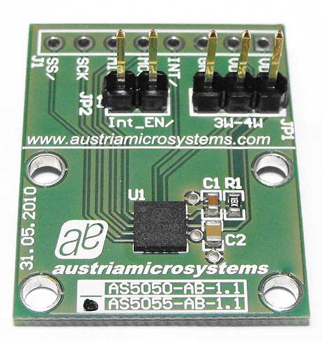
The evaluation board didn't come with a magnet or other encoder hardware. Here's a picture of the board.
I layered a few boards of expanded PVC together in order to sandwich in a set bearings. I attached a pair of axially magnetized magnets to the end of a carbon fiber rod with some PolyMorph. I held the shaft in place with some more PolyMorph with a couple of washer to smooth out the rotation some.
Here's a picture of my contraption.

My M2.5 nylon bolts weren't long enough to go through all three layers of expanded PVC and still reach to the bottom of the PCB so I had to start the bolt from the bottom layer of the boards. I used a couple of additional bolts to secure the layers together. It shouldn't come as a surprise the readings from the encoder flucutated a lot with this setup. I have some sample magnets arriving today that should let me build a more stable rig (the magnets should be diametrically magnetized instead of axially magnetized).
Even with the fluctuation, it was fun to see the read out from the encoder. The encoder outputs a 12-bit value. My current setup can't take advantage of the sensors full resolution.
Here's a video of the sensor in action. I'm using a QuickStart board to read the sensor and sending the data to a little 7-segment display. The output should range from 0 to 4095.
Edit: See post #15 for latest video (it's a lot better than this video).

The big advantage magnetic encoders have over pots or other encoders is they don't wear out. I suppose the bearings or some other part of the hardware could wear out but the magnet/chip interface is contactless.
Here's a close up of the magnet suspended above the encoder.

This is a paid job (software only). I will likely be able to release the code I write sometime in the future (hopefully soon) but for now, I can't post it.
I think this sensor has a lot of potential. One possible application would be a continuous rotation servo that provides position feedback.
I'm working on learning how to read the input from astriamicrosystems' AS5055 chip.
Graham Stabler had suggested these type of encoders as a substitute for a potentiometer.
I purchased a set of their evaluation boards (and some chips) from Digi-Key.
The chip has several different ways it can communicate (all of them are SPI).
The three wire, read only method looked the easiest so I tried it first.
The evaluation board didn't come with a magnet or other encoder hardware. Here's a picture of the board.
I layered a few boards of expanded PVC together in order to sandwich in a set bearings. I attached a pair of axially magnetized magnets to the end of a carbon fiber rod with some PolyMorph. I held the shaft in place with some more PolyMorph with a couple of washer to smooth out the rotation some.
Here's a picture of my contraption.
My M2.5 nylon bolts weren't long enough to go through all three layers of expanded PVC and still reach to the bottom of the PCB so I had to start the bolt from the bottom layer of the boards. I used a couple of additional bolts to secure the layers together. It shouldn't come as a surprise the readings from the encoder flucutated a lot with this setup. I have some sample magnets arriving today that should let me build a more stable rig (the magnets should be diametrically magnetized instead of axially magnetized).
Even with the fluctuation, it was fun to see the read out from the encoder. The encoder outputs a 12-bit value. My current setup can't take advantage of the sensors full resolution.
Here's a video of the sensor in action. I'm using a QuickStart board to read the sensor and sending the data to a little 7-segment display. The output should range from 0 to 4095.
Edit: See post #15 for latest video (it's a lot better than this video).
The big advantage magnetic encoders have over pots or other encoders is they don't wear out. I suppose the bearings or some other part of the hardware could wear out but the magnet/chip interface is contactless.
Here's a close up of the magnet suspended above the encoder.
This is a paid job (software only). I will likely be able to release the code I write sometime in the future (hopefully soon) but for now, I can't post it.
I think this sensor has a lot of potential. One possible application would be a continuous rotation servo that provides position feedback.
Comments
See post #34 for details.
Edit(3/11/15): I have deleted the archive AS5055Demo120526a - Archive [Date 2012.05.26 Time 15.21].zip
I plan to upload this program or an improved version to my GitHub account.
If there isn't a replacement on GitHub send me a message and I'll make sure to upload the replacement code.
cool that you are working with this magnetic encoder.
the people from 01mechatronics (the website does no longer exist) developed a small board for "super-modifying" RC-servos
http://code.google.com/p/zosupermodified/
maybe it is useful to look into their code which is GNU GPL
I would love to see somebody writing code for the propeller-chip to read out these devices
best regards
Stefan
Really interesting, and great use of Polymorph. Thanks for sharing.
The values on the display are steadier than I would have expected for such a setup. Any idea what kind of response time is possible (rpm etc)?
You mentioned getting different magnets. What was your source for the replacement magnets. I have a couple of sample chips I want to experiment with.
Jim
Thanks Stefan.
The "Super-Modified" servos look like they use a AS5145 chip. Those have some extra features like quadrature output and PWM output. They also cost more ($9 in quantity of 100). The AS5055 cost about $5 if you buy 100 at a time.
The AS5055 has the same 12-bit resolution and I think the smaller size of the AS5055 would make it easier to use as a pot replacement in a servo.
When you say "I would love to see somebody writing code for the propeller-chip to read out these devices" are you referring to the Super-Modified board or the encoder I'm working on?
I plan to make a small board using these AS5055 chips and once I do, I'll be free to release the code. I doubt I'll be able to get a board designed and made before the upcoming Expo since I'm trying to get some other projects that are further along finished to bring with me for "show and tell".
These AS5055 chips can be daisy-chained together which should make using a bunch of them not use a lot of pins (it will require four Propeller pins). In daisy-chain mode, each chip doesn't require a separate chip select pin as is usually required by SPI devices. The daisy-chain does reduce the frequency each chip can be read since they are all read one after the other.
Thanks Tubular.
Yeah, I wasn't expecting rock solid performance from my blob of parts. I was really pleased to get it working as well as it did with this setup.
The PASM code takes 56us to read from the device.
I don't know how many rpm it could read. I think once you're trying to measure rpm above a certain point, you'd be better off with just a single hall-effect sensor since the position within the rotation would no longer be very important.
I think these sensors would work well with a servo as Stephan suggested. I think it would be really cool to be able to know the position of a continuous rotation servo with better than 0.1 degree of accuracy. I'm pretty sure this sensor could be read fast enough to monitor the speed of even the fastest CR servos.
Jim,
I think you'll want magnets that are diametrically magnetized. I think the recommended size is 6mm diameter and about 2.5mm thick.
I had requested some magnet samples from austriamicrosystems. The sample that looks like it will work the best (it's the size I mentioned above) has a part ID of 990600037. The samples were sent FedEx. I'm sure the shipping cost them much more the magnets.
I haven't mounted the new magnet yet. It should let me build a more stable rig. I'll likely use 3/8" plexiglass as the support structure for the encoder this time.
The main thing is to have propeller-code to read the encoder at all. I guess the SPI-protocol is the same for AS5145 and AS5055. Is this right?
I think SPI will be faster than reading PWM. Would a DC-servo-control need quadrature-output
or could it work on just 12bit values with looking at increase / decrease the values to conclude clockwise/counterclockwise rotation?
best regards
Stefan
I use these on my robot motors.
I dont rember if they are 10 bit or 12?
You think the chips are expensive wait till ya price the 3mm radial magnets.
http://reprap.org/wiki/Magnetic_Rotary_Encoder_1.0
I don't think you'd need quadrature output. I think seeing the 12-bit value change would be enough to know the direction of rotation.
Reading the SPI output is kind of trivial (so many things are once you know how). A couple of years ago I would have been lost trying to read from this chip but since I've worked on other SPI projects, this one isn't too hard.
I can release the code once I have gerber files for making a board with this chip (part of the deal that was worked out with the person paying me to do this).
I'm hoping to take advantage of the small size of this chip and make a little board to take the place of a servo's pot.
Those encoders use a AS5140 chip which is the 10-bit sibling of the AS5145.
The AS5055 has a recommended magnet size of 6mm diameter. Smaller magnets will work by the output wont be as linear as the angle of rotation changes.
I used a piece of scrap plexiglass as the main structure of the encoder.
I used a M5 nylon bolt for the encoder shaft and as the magnet holder.
I milled a hole slightly smaller than the magnet in the head of the bolt. I was pleasantly surprised I was able to press fit the magnet into the hole on my first attempt. The milling was all done on a drill press. Any holes wider than 11/64" had to be made by repeatedly plunging the bit (I did use a milling bit) into the work piece.
I milled out an area for the bolt head around the 5mm central hole. You can see the encoder chip through the 5mm hole in the picture above.
Here's a picure of the two encoders side by side.
As you can see, this second encoder is much more rigid than my first attempt.
While this new encoder was a lot more stable than my first attempt, the last digit of the display still flickered different values. I used a running average algorithm to see if I could filter the output with software. I was amazed at the difference the software filter made.
Here's a video showing off the new hardware and software.
Initially the filtering algorithm had trouble when the encoder was close to the 4,095 to 0 transition. I ended up using a second set of numbers to computed the average when the reading was near this transition. I added 4,096 to the low values before averaging them.
There's a lot of fine tuning that could be done with the software filter but it's working well enough now for my to continue on and get the SPI daisy-chain mode to work.
So far this project has been a lot of fun.
how do you keep the magnet in a constant distance to the chip? On the picture I can't see anything that has this function.
best regards
Stefan
I pulled on the bolt as I turned it clockwise.
Counter-clockwise movement makes the bolt push against the top of the plexiglass.
I considered adding a thrust bearing and a couple of nuts to hold the bolt up but I wanted to get back to working on the software and the current version of the hardware works good enough for testing.
I also tested a 1/16" magnet today. It fit in the center of the philips "X" on the head of the bolt without needing to modify the bolt at all. The encoder could read the position of the little magnet just fine. Its output wont be as linear as the larger magnet though.
I'm just about ready to test my daisy-chain software.
-Phil
You're correct. The datasheet says the magnet should be 0.5mm to 2.0mm above the chip. The Propeller can still read the magnet's rotation when it's touching the chip. I haven't tested to see how far away the magnet can be. I think when the magnet is father away from the sensor, the sensor is more susceptible to noise. Using a metal shaft (even non-ferrous metals) to hold the magnet could also cause noise problems.
If you get a chance I'd be really interested whether a "longer" magnet would still give reasonable results. I'm thinking something like a horseshoe magnet which has an "open" centre and side. ie you would still have the magnetic flux cutting across the sensor surface but the pole ends of the magnet further out
I guess you could test with 3 or 4 of your magnets end to end, with minimal flux escaping where the middle ends connect.
I'd be glad to test any arrangement of magnets you'd like.
I don't think I have a horseshoe magnet to test.
I have ten each of these magnets.
0.25" cube magnets.
3/16" ring magnets.
Let me know what configurations you'd like me to test.
I'll likely try two of the .25" magnets to start with.
My first setup uses two magnets stacked on top of each other. The magnets are 1/8" thick. I don't think any of the earlier pictures show how the magnets are arranged.
I found a picture that kind of shows how the magets are stacked.
What I was thinking was if you can have the magnetic poles further apart,with the flux "cutting" across the surface of the chip, it may be easier to measure the position of servo horns for example, or other cases where you don't have access to a shaft poking out the rear of a motor
I added a feature to the filtering algorithm to sense when the encoder is in motion. When the encoder is in motion, fewer samples are used to generate an average. This lets the new position be updated faster on the display.
I'm using a second 7-segment display to show the output from the second encoder. I thought having two small displays made it easier to see which number corresponded to which encoder than displaying both numbers on a single larger display.
Here's the video showing the two displays in action.
I'm planning on making several different boards using these sensors. I want some of the boards to be small enough to use a pot replacements in servos. I'd also like to make some boards about the same size as these evaluation boards for panel mounting with a knob.
I tried something like this and it worked.
These sensors also worked with the magnet under the sensor. They worked if the magnet was about an inch above the sensor. I doubt readings will be as stable or as accurate with the magnet held father away than recommended, but it looks like the sensor is sensitive enough that you'd get some sort of reading at increased distances.
As I mentioned ealier, I also tried a smaller magnet. Here's a picture of one of the small magnets Kirk Frasure sent me.
I was able to press fit the maget in the "X" on the bolt head. The sensors read the position of this smaller magnet just fine. The main problem with using a small magnet or other unrecommended mounting techniques is the output from the sensor wont be linear throughout the rotation of the magnet.
I would like to enquire as to the schematic used for interconnection with your microcontroller ? Attached is a schematic of how i interpreted the uC-AS5055 interface from the encoder datasheet and Application note provided by Austria Microsystems.
I intend to program in MikroC Pro for AVR using the SPI Library. I would like to know whether or not it would be suitable to apply an active low SS/ signal and then read the data in via the SPI buffer.
Thanks in advance
welcome to the propeller-chip-forum.
hm - not sure what this post about AVR-C has to do with the propeller-chip.
Now if programming with the propeller-chip you simply dedicate a cog for the SPI-communication reading in the values and serve them via HUB-RAM to the other cogs.
As propeller-assembly offers conditional execution on EVERY ASM-command this can be done easily,
best regards
Stefan
AustriaMicroSystems has some apnotes about uses SPI over longer wires I plan to implement but I don't recall if their recommended wiring matches your schematic or not.
I used 3.3V on both the VDD and VDDp pins on the adapter board.
I imagine the AVR SPI library should be able to read from these devices. You do need to write and read 16 bits at a time. I think AMS has some example C code to read from these chips in one of their apnotes.
Graham
I think you're the one who suggested these to Kirk.
It was a lot of fun to write a driver for these chips.
Once I have a circuit board made I can release the code (hopefully within a month).
I have a bunch of projects where I'd like to use these chips.
Jim