

(Better) Crystal Sharing
 MacTuxLin
Posts: 821
MacTuxLin
Posts: 821
Hi All,
Please let me know if this is workable? Thanks.
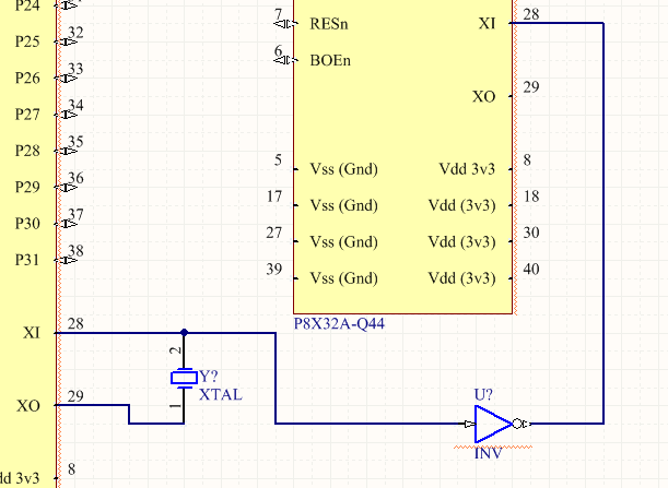
Updated: I have added the inverter according to Phil's advice.
Please let me know if this is workable? Thanks.
Updated: I have added the inverter according to Phil's advice.
Comments
-Phil
As soon as the two Props resets were commoned then all was ok. I did wonder about if the slave's RCFAST was a lot faster than the master's if the same would occure but swapping around the Props didn't seem to change anything
Thanks Toby. I planned to test it tomorrow as I was worried what you've mentioned might happen. The first Prop1 would have a possibility to reboot while the second Prop1 is in the mist of an operation. That's why I could not use the usual setup.
Thanks.
I'd tie a line from the prop that has both sides of the crystal connected to the reset line of the prop with the crystal disconnected. Have the beginning of your program on the 'master' prop reset the slave prop. That way if the master gets reset the slave won't go crazy when it loses its clock source.
What does the DI line on the master look like from the period of reset to up and running?
The way I see it, having the slave stop, then start will only happen cleanly and with proper timing if the DI input outputs say... 5MHz one moment, then for the next x time it outputs nothing (or low), then starts outputting 5MHz again. At no time is it allowed to output a different frequency during the boot phase.
:-) This solution may end up being super simple if it's a clean transition.
Also, could I slave say... 4 propellers to a single propeller's DI line? I imagine each propeller won't pull much from it.
You really don't want to connect XO to several other Props' XI inputs. XO is not designed to drive anything other than a single crystal. The additional capacitance of the PCB traces will load it down and the oscillator may not start up reliably. The extra capacitance may also decrease the oscillation frequency of the crystal. At the very least, you'll need some kind of buffer mounted close to the XO pin along with the crystal and keep the traces as short as possible.
(or the more focused, but not quite as cheap/multisourced, 74AUP1Zxx)
One Gate manages the Xtal, (no pauses on RST) and the other Gate buffers and speeds up the edges a little, for all the driven Prop XI's
Ok...so I hear two answers on this.
1) It's ok to drive ONE prop from another prop. It is not ok to drive MORE THAN ONE prop from another prop
and
2) It's not ok to drive ANY NUMBER of props from another prop without running it through a buffer such as the 2GU04. Also, the buffer should be physically located near the prop to minimize lead capacitance so as to not destabilize the crystal driving circuitry and possible cause it to not start up.
...also, here is a link to the 2GU04 buffer that was referenced by jmp...in case anyone wants to see
http://www.onsemi.com/pub_link/Collateral/NLX2GU04-D.PDF
That is a nice fact to know.
Bruce
Makes sense... The propeller ticks along based on its clock source. If you stop its clock...you stop the propeller. Switching oscillator inputs means it's doing something...aka...not stopped.
Makes perfect sense.
As Leon says I have used AVRs like this but with them the OSC options are set by flags and so kick in from the start.
Could you please elaborate? I don't have 2GU04 but I have SN74AUP1G04 x 2.
Thanks.
Just wire the Gates you have in series. See Fig 14 in
http://www.nxp.com/documents/data_sheet/74AUP1Z04.pdf
R1 is often used to adjust drive to the Xtal, and add a little phase shift too.
Ok, to follow that diagram...
http://www.nxp.com/documents/data_sheet/74AUP1Z04.pdf
omit c1, and c2 as the propeller's crystal drive circuitry takes care of that.
r1 is based on the reactance of the propeller's internal motion capactiors, which are likely around .010pF. The reactance of .010pF @ 5MHz is around 3.2 Megaohms. So to round that to a standard 5% resistor that would be 3.3 megaohms.
You've lost me here - you use All Prop's in External drive mode, and so you are building a external stand alone oscillator.
In a 1GU04 you need a bias resistor, 2 caps and a R1 drive resistor, which is usually under 10K at MHz frequencies.
See also
http://media.digikey.com/pdf/Data%20Sheets/NXP%20PDFs/74AUP1Z04EVB.pdf
This gives R1 = 330 ohms at 25MHz so expect ~1.5k at 5MHz
I never use 2 capacitors external to a propeller when I hook up a crystal. The propeller has those built in.
I looked at figure 14 and it said that R1 (the drive resistor) should be selected such its value is approximately equal to the reactance of C1 at the crystal drive frequency. This will result in an input to the crystal of 50% of the rail to rail output of X2.
Also, Rbias is internal to the 74AUP1Z04
Obviously we (I) am misunderstanding your meaning. Would you mind going into MS paint and drawing up a quick sketch of how you propose hooking up the 74AUP1Z04 such that a single crystal drives two propellers?
Just copy the sch here :
http://media.digikey.com/pdf/Data%20...AUP1Z04EVB.pdf
The 1GU04 which you said you have, does not include the bias resistor.
See comments above, the consensus is with TWO props, it is best to slave both, so any Prop caps are not used.
Since you have it on the bench...it would help me if you could do this...
Write a program in both props that toggles a pin at a regular interval, say ~1kHz. Hook up both props to a logic analyzer and look at that pin. Start a data capture. Reboot the master prop. Give it a second to capture more data. Stop the data capture.
Then post up the resultant waveform. If you have a nice logic analyzer such as the salae logic analyzer post up the capture file. I'd love to see.
Thanks!