

Help regarding PWM for H-BRIDGES ....
 RITESH KAKKAR
Posts: 254
RITESH KAKKAR
Posts: 254
Hello,
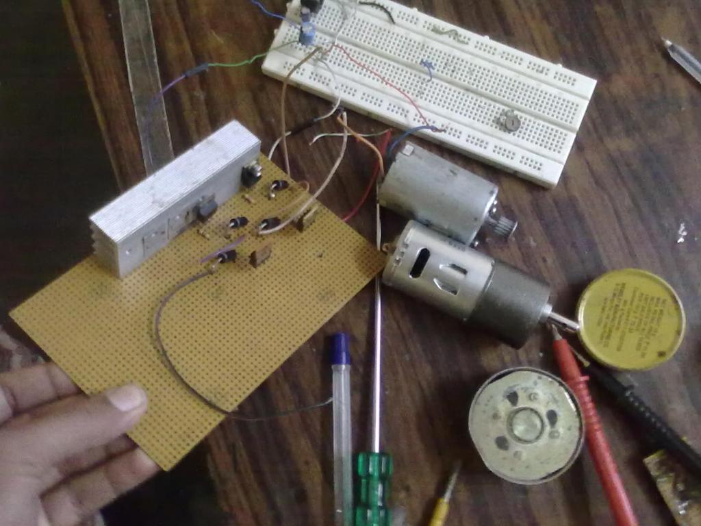
I have build H-BRIDGES for Brushed DC motor now i want to control its speed using PWM.So, I need help on building code and suggestion my circuit is working fine with 24V supply.
.
I have build H-BRIDGES for Brushed DC motor now i want to control its speed using PWM.So, I need help on building code and suggestion my circuit is working fine with 24V supply.
.
Comments
It would be a good idea to study this app note for Propeller Counters to understand how the Propeller generates PWM.
http://www.parallaxsemiconductor.com/an001
There are PWM objects in the Object Exchange that makes generating PWM very easy. Search the Obj Exchange for "PWM", "motor control". There are several objects there to control speed for DC motors.
Yes using pot meters..
.
There may be objects better suited to DC motors, I do not use DC motors but someone else may have a suggestion. The object below is very easy to use, and has an example. You start the object and give it the pin you want to use, specify the period and duty cycle. One you get this part working, then you can tackle how to read the POT into the Prop, but it is not a good idea to tackle 2 things at once.
http://obex.parallax.com/objects/216/
please tell what will be method to control i think it will use ADC..?
Will running motor at low speed by switching freq give lots of spark how to remove it?
Here is code no schematic...
{{ ***************************************** * generic ADC driver v1.0 * * Author: Beau Schwabe * * Copyright (c) 2007 Parallax * * See end of file for terms of use. * ***************************************** }} CON SDF = 6 'sigma-delta feedback SDI = 7 'sigma-delta input PUB SigmaDelta (sample) cognew(@asm_entry, sample) 'launch assembly program in a COG DAT org asm_entry mov dira,#1<<SDF 'make SDF pin an output movs ctra,#SDI 'POS W/FEEDBACK mode for CTRA movd ctra,#SDF movi ctra,#%01001_000 mov frqa,#1 mov asm_c,cnt 'prepare for WAITCNT loop add asm_c,asm_cycles :loop waitcnt asm_c,asm_cycles 'wait for next CNT value '(timing is determinant after WAITCNT) mov asm_new,phsa 'capture PHSA mov asm_sample,asm_new 'compute sample from 'new' - 'old' sub asm_sample,asm_old mov asm_old,asm_new wrlong asm_sample,par 'write sample back to Spin variable "sample" '(WRLONG introduces timing indeterminancy here..) '(..since it must sync to the HUB) jmp #:loop 'wait for next sample asm_cycles long $FFFF '(use $FFFF for 16-bit, $FFF for 12-bit, or $FF for 8-bit) asm_c res 1 'uninitialized variables follow emitted data asm_cnt res 1 asm_new res 1 asm_old res 1 asm_sample res 1 asm_temp res 1 DAT {{ +------------------------------------------------------------------------------------------------------------------------------+ ¦ TERMS OF USE: MIT License ¦ +------------------------------------------------------------------------------------------------------------------------------¦ ¦Permission is hereby granted, free of charge, to any person obtaining a copy of this software and associated documentation ¦ ¦files (the "Software"), to deal in the Software without restriction, including without limitation the rights to use, copy, ¦ ¦modify, merge, publish, distribute, sublicense, and/or sell copies of the Software, and to permit persons to whom the Software¦ ¦is furnished to do so, subject to the following conditions: ¦ ¦ ¦ ¦The above copyright notice and this permission notice shall be included in all copies or substantial portions of the Software.¦ ¦ ¦ ¦THE SOFTWARE IS PROVIDED "AS IS", WITHOUT WARRANTY OF ANY KIND, EXPRESS OR IMPLIED, INCLUDING BUT NOT LIMITED TO THE ¦ ¦WARRANTIES OF MERCHANTABILITY, FITNESS FOR A PARTICULAR PURPOSE AND NONINFRINGEMENT. IN NO EVENT SHALL THE AUTHORS OR ¦ ¦COPYRIGHT HOLDERS BE LIABLE FOR ANY CLAIM, DAMAGES OR OTHER LIABILITY, WHETHER IN AN ACTION OF CONTRACT, TORT OR OTHERWISE, ¦ ¦ARISING FROM, OUT OF OR IN CONNECTION WITH THE SOFTWARE OR THE USE OR OTHER DEALINGS IN THE SOFTWARE. ¦ +------------------------------------------------------------------------------------------------------------------------------+ }}I'm very ignorant about MOSFETs but I've been reading this thread.
I'm not sure how the code you posted relates to your question about sparks. The code you posted could be used to read a pot. There is an apnote about using the code here. The pdf has this schematic.
There is a place on the QuickStart board to add these parts. There are the two Greek letters Delta and Sigma above the touchpad P5. This is where you'd add the needed resistors and capacitors.
I've personally never added a delta-sigma curcuit to any of my boards. I usually just use an ADC chip.
Now about the sparks. I don't think I understood your question. When you run the motor at slow speed you have a problem with sparks? What code are you using to control the motor? What parameters are you using?
I hope you're having a good break from school (if you're still on break).
I think first i should control motor by software then come to hardware (ADC with pot meter)..
I was testing motor using Repeat and wait ( square wave) just testing giving lot of vibration and speed was not control..!!
So, i want some basic help to start PWM in Quick start Board.
I think it require snubber ckt i don't know how to build it..
dira[pin] := 1
outa[pin] :=1 ' see if this turns on hbridge, motor full speed.
Try this:
''Demonstration of PWM version of NCO/PWM counter mode CON _clkmode = xtal1 + pll16x _xinfreq = 5_000_000 pwm1pin = 12 'set your pin here VAR OBJ pwm1 : "pwmasm" PUB go | x pwm1.start(pwm1pin) pwm1.setperiod(1000) ' adjust this to find a smooth running value. motors vary, speeds vary, loads vary. this is freq of the cycle pwm1.SetDuty(100) ' adjust from 0 - 100, full off to full on repeat 'keep aliveYes it is working fine..!!
the code you have given is not working..
It is asking for PWMASM..!!
but then also showing error..!!
It should be located in the folder that contains all your other spin files.
OK, when i change the freq and duty cycle at low speed the torque become small and the motor fail to restart..!!
When i change the of duty cycle the motor torque reduce and on increasing the freq the motor start running not in low freq..??
Just because the program can go to 0 duty, that does not mean the motor will function properly at all duty cycles. Also, It is not clear that your hbridge is sufficient to operate at various frequencies/duty cycles. The circuit you have may not be switching nicely with PWM, since on each on/off pulse, you may have a point where both 24v and GND are on at the same time. A driver IC will prevent this. I think you are only going to have so much success with that circuit. It may work great when wired direct to a control voltage, but switching it is an entirely different matter. If it were me, I would test for now with ONLY the high side switching, connect the other side of the motor direct to GND. Then you can determine how the software is really behaving without concern for how nicely your circuit is behaving.
I am also doing the same..and the motor working fine..!!
But the code seems to be very complex.
Not sure what you mean by complex, that is about as simple as it gets for PWM control.
I am talking of that all code pwmasm ones...seems to be very hard for me.
OK, now if i want to go with pot meter then how to control speed.?
apply 24v
break
apply 24v
break
This is not a good method to run the motor, as it will be fighting itself. It is best to disable the NPN mosfet so it is not taking the motor to GND. Just switch the PNP only.
There is another thread already discussing how to use a pot. With a pot, you would put 3.3V on one side of the pot, GND on the other, then the wiper goes to the Prop based on the schematic shown in the ADC object. You read the ADC value, then create a ratio to PWM. I think you need to spend time first learning how to read a value fro, the Prop ADC, display the value somewhere(LCD,VGA, terminal etc). Once you can change the pot and see the result, you can learn to convert the value to PWM duty.
Hi again,
OK you are thinking that i am using H-BRIDGES one side only as indicated in schematic its not true i am using both side 4 MOSFET a complete H-BRIDGES...The schematic is just for understanding the concept..!!
OK, As QS also have a ADC converter but iu have to put C and R on it as suggested by Duage..I think i will like t to use ADC chip.!!
please suggest which one to use?
Ritesh,
I suggested some ADC chips in post #3 of this thread.
As I said before, I don't understand MOSFETs enough to help but it looks like T Chap knows about them. It's still unclear to me what schematic you are using. It might help T Chap if you post the exact schematic you are using (so he can better help you).
Good luck.
Hi again,
My circuit is working fine..!!( using IRF540/9540 and LM339)
I have tested it up to 6-7amps at 24V. OK, i will pot schematic soon.
I t will be better to use serial or // ADC chip?? I don't want to use that sigma and delta. i will assemble extra PCB for ADC from pot meter.
I think a serial ADC would be a good choice here.
I've only used a parallel ADC when I needed lots of samples, really fast, for video capture on the Prop. (Surprisingly, the delta-sigma curcuit can also capture video.)
As I mentioned in the thread I linked to earlier, my favorite ADC is the MCP3208 since it has 8-channels and doesn't cost much more the chips that only have two or four channels.
One chip I didn't mention in the other thread is the MCP3002. I like this chip because it's so cheap. I usually buy 10 at a time so they cost even less ($2.07). The MCP3002 only has 10-bit resolution (0 to 1023) compared to the MCP3208's 12-bit (0 to 4095), but for most applications, 10-bits is plenty of resolution. I know there are already objects for these chips so they should not be very hard to add to your project.