Shop OBEX P1 Docs P2 Docs Learn Events
A little propeller board — Parallax Forums

A little propeller board

Graham StablerGraham Stabler Posts: 2,507
edited 2011-08-16 07:47 in Propeller 1
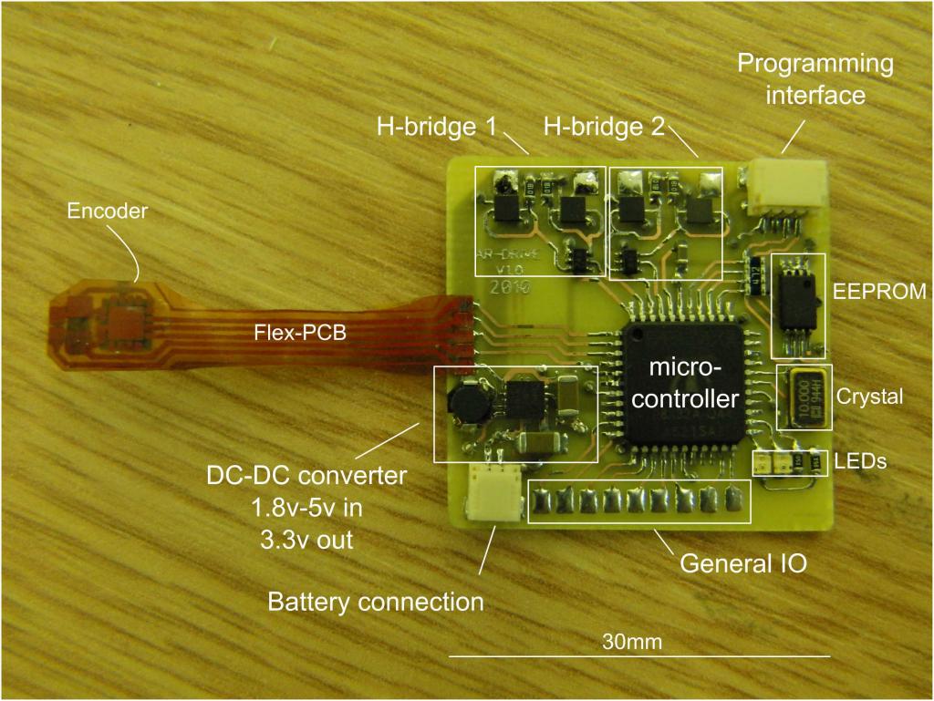
I've been meaning to post a pic of this for a while, something I developed as part of my research. Propeller, eeprom, two h-bridges and buck-boost converter (to run from lipoly 3-4.2v in 3.3v out) and the somewhat more application specific magnetic encoder on homemade flex PCB.

Double sided PCB with wire for vias but components on the top only. Soldering the dual mosfets was a real pain but got there in the end. I think they are rated for something like 7A with suitable PCB but I will run sub 1amp.

Graham

pcb.jpg
pcb.jpg 122.5K

Comments

  • Cluso99Cluso99 Posts: 18,066
    edited 2011-08-15 01:39
    Nice and tiny Graham. What is the size?
  • Graham StablerGraham Stabler Posts: 2,507
    edited 2011-08-15 01:41
    There is a scale on the picture, about 30mm X 30mm, ~1.2"X1.2"
  • FranklinFranklin Posts: 4,747
    edited 2011-08-15 07:57
    Which chip did you use for the voltage converter?
  • Graham StablerGraham Stabler Posts: 2,507
    edited 2011-08-15 08:01
    It is a TPS63001 by TI, another pain to solder :)
  • SapiehaSapieha Posts: 2,964
    edited 2011-08-15 08:03
    Hi Graham.

    Nice board.

    What type of driver IC's -- that ones 6 pin's You use to drive H-Bridges!
  • Graham StablerGraham Stabler Posts: 2,507
    edited 2011-08-15 08:08
    Sapieha, I don't think it is a proper solution for high switching frequencies, I took inspiration from the output drives of small brushless speed controllers as my main hope was a light weight development system. So they are just dual transistors, the pull gate down to ground otherwise it is pulled up by a resistor. The part is MUN5211DW1T1G

    This thing is supposed to go in flying machines if I work out the kinks.

    Graham
  • SapiehaSapieha Posts: 2,964
    edited 2011-08-15 08:21
    Hi Graham.

    Thanks

    I don't need big frequencies to.
  • Zap-oZap-o Posts: 452
    edited 2011-08-15 08:40
    Nice board ! Can I ask what the part number for the xtal is? I have been looking for a xtal smaller than what I am using and that looks like the one.
  • Graham StablerGraham Stabler Posts: 2,507
    edited 2011-08-15 08:44
    Zap, I can't remember if I nabbed the part number from Phil's (PhiPi) propeller backpack (diagram on parallax page for it) or if I just selected the first small crystal that seemed to meet the specs roughly. In any case the part is HCX-5SB at least that is the range it comes from.

    I definitely stole the idea of the array of pull up resistors for programming from Phil!

    Graham
  • Graham StablerGraham Stabler Posts: 2,507
    edited 2011-08-15 08:49
    May be of some interest, or at least someone can tell me how bad it is.

    bot.JPG

    top.JPG
    738 x 689 - 45K
    731 x 684 - 112K
    bot.JPG 44.8K
    top.JPG 112.2K
  • Phil Pilgrim (PhiPi)Phil Pilgrim (PhiPi) Posts: 23,514
    edited 2011-08-15 08:57
    Graham,

    I know you've been studying flying-insect kinematics for a long time. Is this the inevitable next stage? IOW, do the dual H-bridges drive the wings of a radio-controlled moth? :)

    -Phil
  • prof_brainoprof_braino Posts: 4,313
    edited 2011-08-15 09:15
    This thing is supposed to go in flying machines if I work out the kinks.

    Would this be suitable for something like Festo robo bird that erco posted?

    http://forums.parallax.com/showthread.php?133653-Robo-Bird

    I've been wanting one of these since I was ten years old, but never got the wing motion right. Seems so simple now that someone else has done it.
  • LawsonLawson Posts: 870
    edited 2011-08-15 22:00
    My only major nit-pick is that the prop and Fet drivers should connect to power ground directly under the FETs and nowhere else. This will insure that transient voltages on the power ground trace have a minimal effect on the FET gate drive voltage. Worst case, you might be able to fry the gate drive transistors. Looks like you're driving the H-bridge in a CMOS inverter configuration, I assume you've picked the FETs so that shoot-through (both FETs half on shorting the power rails) current is low? (unlikely to be a problem with most FETs and 3.3v on the gates) Any reason you're not direct driving the FETs with a prop pin? It's likely to switch faster, and work even with variations in the input voltage.

    Lawson
  • Graham StablerGraham Stabler Posts: 2,507
    edited 2011-08-16 02:05
    Phil, not a moth but a giant hoverfly.

    Prof, nothing like that. BTW, what Festo did is very similar to Holst and Hertzog, check the link at the top of this page: http://www.indoor.flyer.co.uk/buzzard.htm This page shows my attempt at a model with actively twisting wings a la Holst. Notice that I also tested mine on a ring that goes around and around like Festo did :) I did this 6 years ago.

    Lawson, not sure I understand the grounding issue but seems to work. The high side mosfet needs the battery voltage to turn it off hence I can't drive from the propeller pin at 3.3v.

    Graham
  • LawsonLawson Posts: 870
    edited 2011-08-16 07:47
    Lawson, not sure I understand the grounding issue but seems to work. The high side mosfet needs the battery voltage to turn it off hence I can't drive from the propeller pin at 3.3v.

    Graham

    The grounding issue is something I've seen in other higher power H-bridge designs. Basically, the power ground trace acts as a tiny inductor so when the input current changes due to the fets switching, a voltage is induced along the trace. In higher power/speed situations this voltage can get high enough to fry the gate or driver if logic ground isn't pulled from under the Fet gates. (in your case, power and power-ground are tightly paired which helps a lot by lowering inductance)

    For the Fets I'd have to look at the Idd-Vgs curves to be sure, but the p-fet may be off enough with -0.9v on it's gate (fresh charged Li-po) to work fine. Similarly, with a dead Li-po and 0.1 Vgs the p-fet will just be more "off" than usual. I've also had good success with a capacitive level shifter to drive fets. A capacitor goes between the prop pin and the Fet, then two resistors and a diode are used to define the start up state and voltage range of the level-shifter's output. (ironically this likely takes more space than your solution...)

    Lawson
Sign In or Register to comment.