

Mecanum Wheeled Robot with Machine Vision
 Duane Degn
Posts: 10,588
Duane Degn
Posts: 10,588
I've decided to document my latest project.
I've described this project a little here (post #5). Since Hanno has asked about my progress I've decided to continue describing my project in this thread (and not continue to hijack Ravenkallen's thread).
The base for this robot will be a Rover 5 platform from SparkFun. I'm also have a set of mecanum wheels to use with this robot.
I plan to use Hanno's machine vision method with this robot.
Here are some pictures of my Propeller Proto board with a ADC08100 attached to a breakout board.
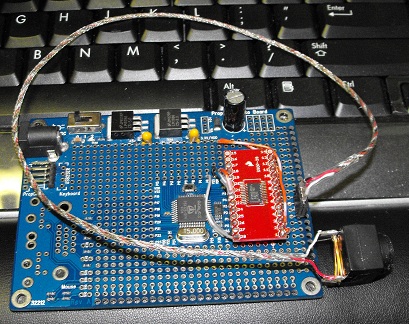
A lot of Hanno's code uses only the top four significant bits of the ADC. I wanted to experiment with all eight bits from the ADC.
From my little PASM experience, I know that the Prop can read fastest from the lowest pins. I attached the ADC output pins to pins 0 to 7 of the Prop. Pin 8 is connected to the ADC's clock pin.
I removed two pins from a row of male headers and bent the pins inward from both sides to connect the eight output pins from the ADC to the desired pins on the Prop.
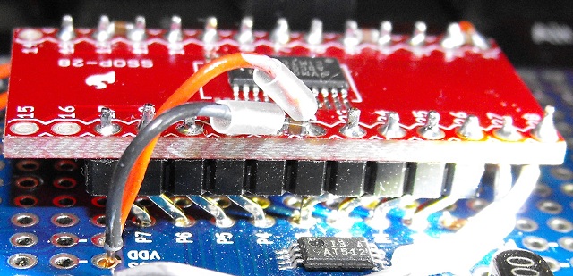
I'm hoping to use the camera with a laser for range finding. I want to be able to detect obstacles and drop offs (steps). I also want to use it this set up for other machine vision experiments.
So far I've just sent the INA values for pins 7 through 0 to PST. I get higher values when I point the camera at brighter objects and lower values when it's pointed at darker objects. I think the ADC is working.
While I want this robot to be able to roam around autonomously, I also want to be able to control it remotely. I also want to received information from the robot. My current plan is to use a Nordic nRF24L01+ module to send and receive information from the robot.
Supposedly this module can communicate at 2Mbps. One of my goals is to modify the current driver to take advantage of this speed.
The Rover 5 has four motors and four quadrature encoders. The manual doesn't specify with wire does what with the encoders. As one would expect the red wire is 5V the black is ground with the white and yellow wires are the signal wires.
The Mecanum wheels come with hubs that are a little too large to fit in the center of the wheel. I used a 4-40 bolt with a nut and washers to mount the hub in my drill press. I then just touched some sandpaper to the spinning hub until it fit snuggly inside the center of the wheel.
The center hole of the hubs are also a little too small for the Rover 5's shafts. I used a 4mm drill to bore the hole a little larger. I temporarily attached the hubs to the wheels to make them easier to hold while I used the drill press on the hubs.
Here's a pdf file I found on using Mecanum wheels.
ControllingMecanumDrive[1].pdf
As I've started to add up the number of pins I'll need for this project, I'm starting to think I'll need a second Prop on this project.
Here's my pin count so far:
Machine vision ADC: 9
Nordic module: 6? (I'm not sure if I need all six or if I can get by with 5)
Shift registers for motor control, laser and LEDs (you have to have LEDs on a robot): 3
Quadrature encoders: 8
Emic text to speech: 3
I'd like to keep pins 28 & 29 free for I2C devices: 2
I also want to keep pins 30 & 31 free for debugging: 2
So that leaves me with -1 pins. I'm pretty sure there are other devices I'd like to use with this robot that will take extra pins.
I think I'll move motor control to a second board. I'm not sure if I'll use a second Propeller Proto board or if I'll just use a small protoboard. I'll need to think about where I'll put all the chips I'll be needing. I plan to use SN754410 chips to control the motors. I'll probably stack a couple of these chips on top of each other to make sure they can handle the current. The stall current on the robot's motors is 2.5A.
Well that's it for now. Man, it sure takes a lot of time to document this stuff.
I'm starting a blog. I don't have a link yet because I wanted to link to this post in my first blog post so I have submitted my first blog post yet.
Hopefully I'll keep this thread current with my progress.
Duane
I've described this project a little here (post #5). Since Hanno has asked about my progress I've decided to continue describing my project in this thread (and not continue to hijack Ravenkallen's thread).
The base for this robot will be a Rover 5 platform from SparkFun. I'm also have a set of mecanum wheels to use with this robot.
I plan to use Hanno's machine vision method with this robot.
Here are some pictures of my Propeller Proto board with a ADC08100 attached to a breakout board.
A lot of Hanno's code uses only the top four significant bits of the ADC. I wanted to experiment with all eight bits from the ADC.
From my little PASM experience, I know that the Prop can read fastest from the lowest pins. I attached the ADC output pins to pins 0 to 7 of the Prop. Pin 8 is connected to the ADC's clock pin.
I removed two pins from a row of male headers and bent the pins inward from both sides to connect the eight output pins from the ADC to the desired pins on the Prop.
I'm hoping to use the camera with a laser for range finding. I want to be able to detect obstacles and drop offs (steps). I also want to use it this set up for other machine vision experiments.
So far I've just sent the INA values for pins 7 through 0 to PST. I get higher values when I point the camera at brighter objects and lower values when it's pointed at darker objects. I think the ADC is working.
While I want this robot to be able to roam around autonomously, I also want to be able to control it remotely. I also want to received information from the robot. My current plan is to use a Nordic nRF24L01+ module to send and receive information from the robot.
Supposedly this module can communicate at 2Mbps. One of my goals is to modify the current driver to take advantage of this speed.
The Rover 5 has four motors and four quadrature encoders. The manual doesn't specify with wire does what with the encoders. As one would expect the red wire is 5V the black is ground with the white and yellow wires are the signal wires.
The Mecanum wheels come with hubs that are a little too large to fit in the center of the wheel. I used a 4-40 bolt with a nut and washers to mount the hub in my drill press. I then just touched some sandpaper to the spinning hub until it fit snuggly inside the center of the wheel.
The center hole of the hubs are also a little too small for the Rover 5's shafts. I used a 4mm drill to bore the hole a little larger. I temporarily attached the hubs to the wheels to make them easier to hold while I used the drill press on the hubs.
Here's a pdf file I found on using Mecanum wheels.
ControllingMecanumDrive[1].pdf
As I've started to add up the number of pins I'll need for this project, I'm starting to think I'll need a second Prop on this project.
Here's my pin count so far:
Machine vision ADC: 9
Nordic module: 6? (I'm not sure if I need all six or if I can get by with 5)
Shift registers for motor control, laser and LEDs (you have to have LEDs on a robot): 3
Quadrature encoders: 8
Emic text to speech: 3
I'd like to keep pins 28 & 29 free for I2C devices: 2
I also want to keep pins 30 & 31 free for debugging: 2
So that leaves me with -1 pins. I'm pretty sure there are other devices I'd like to use with this robot that will take extra pins.
I think I'll move motor control to a second board. I'm not sure if I'll use a second Propeller Proto board or if I'll just use a small protoboard. I'll need to think about where I'll put all the chips I'll be needing. I plan to use SN754410 chips to control the motors. I'll probably stack a couple of these chips on top of each other to make sure they can handle the current. The stall current on the robot's motors is 2.5A.
Well that's it for now. Man, it sure takes a lot of time to document this stuff.
I'm starting a blog. I don't have a link yet because I wanted to link to this post in my first blog post so I have submitted my first blog post yet.
Hopefully I'll keep this thread current with my progress.
Duane
Comments
The manual states there are "1000 state changes per 3 wheel rotations." This should give 250 encoder cycles (or periods) per 3 rotations.
I set my power supply to 7.2 volts and hooked up one of the motors. I counted 30 rotations in 20 seconds making the speed 90 rpm. This was with the wheel free to turn. The motor drew about 150 mA when allowed to freely spin like this.
At 90 rpm and with 250 encoder cycles per 3 revolutions the period for the encoders should be 8 ms. The oscilloscope measured the period at 8.08 ms so I think have a pretty good measurement of the rotation speed at 90 rpm.
With the positive power connected to the motor's red wire the motor turned counter-clockwise. The white wire encoder lead the yellow wire encoder by about 1/4 of a period.
I don't think there are any encoder objects in the OBEX to use with four quadrature encoders. This could be a bit of a trick since to move sideways the mecanum wheels have to spin toward each other on one side and away from each other on the other side. I'll need look through the quadrature encoder objects available to see is I can use them or not.
I probably ought to come up with a spin version (of encoder reading and motor control) to start with. I'll just keep the motor speed low until I get a spin version working the way I want. Once I have the logic figured out I'll change it to PASM.
I don't think I finished recording my observations on the current draw of the motors. As I said, the free spinning motor (with mecanum wheel attached) drew about 150 mA. When I tried to slow the wheel down with my hand, it was difficult to get the current above 400 mA. I don't think these motors will draw anywhere near the 2.5A stall current under normal conditions. I think 400 mA is more current than each motor will normally draw. I'm not sure if I'll need to double up on the motor controller chips. (I probably will stack them to be on the safe side and because I have lots of SN754410 chips.)
I think I've decided to use two Propeller Proto boards with this project. I removed the large capacitor on one of the boards to make them easier to stack. The Nordic module fits nicely between the two boards with the antenna sticking out at the edge of the boards near the Prop Plug connection. I'm planning on using the top board for reading the encoders and controlling motors.
Thanks for documenting your ambitious project! I like how you used the breakout board to mount the adc08100 and how you're methodically testing the components. The Propeller is great for breaking complex projects into smaller tasks- each consuming a cog, and then putting everything together at the end. Good luck!
Hanno
Keep it coming I want to know how it goes.
I mentioned in my earlier post, I've started a blog. Here's a link. (There are only two posts so far.)
@Hanno, Thanks for your interest. I didn't feel adventurous enough to try to solder wires to the tiny leads of the ADC chip. The breakout board made the task of connecting the chip to the Propeller much easier. I'm very excited to have some aspects of machine vision working. I was able to adapt your code to use with this project. I doubt I would have tried this without your great tutorials.
@Shylark87, Thanks for your comments. I'm always glad that my efforts to document a project are appreciated by others. Keep on working with the Prop it's a lot of fun. I started using the Propeller a couple of years ago. These forums have made learning to use it a lot easier.
On with the update:
I worked a lot on a driver for the Nordic nRF24L01+ modules I plan to use to control the robot remotely with. The driver in the OBEX didn't work and could only receive (as it turned out only one byte of data). I made the SPI interface much faster and the object can now send and receive full payloads of data at a time. I still plan on improving the object but I was ready to work on something else for a while.
The something else I worked on was an LED array. Ever since seeing Ben Heck stack a bunch of 595 shift registers on top of each other to drive a bunch of LEDs, I've wanted to try something similar. Here's a picture of the monstrosity.
Here's a picture of the front.
I have two Proto Boards stacked on top of each other. The LED array is actually controlled by the bottom board but I didn't have a good way to connect it to the lower board. I have a set of headers that transfer the signals from the lower board to the upper board. The lower board is the same board in my first post on this project. To get the lower board to sit as close as I wanted to the top board, I removed the tall capacitor and I also removed the power connector since the solder tabs of the connector on the top board bumped into the bottom board's connector. I have Vin, 5V, 3.3V and ground of both boards connected to each other. I think this should be okay. Most of the voltage regulator datasheets I've read have stated that they can be run in parallel. The bottom board receives its power from the top board.
Once I had the LED hardware done, I started working on the software. I wanted each LED to have 8 bits of brightness control. The brightness of each LED would be held in a 120 byte array while a cog would monitor these values and send the necessary instructions to the shift registers.
120 LEDs could be controlled with 15 8 bit shift registers. I decided to use 16 shift registers and to break the data in four groups of 30. All 16 shift registers share their clock and latch lines (and Vdd, ground, enable and reset). The data is sent through four lines. One for each set of four shift registers. My thinking was that if I wrote to four data lines at a time, I could increase the refresh rate of the screen. I'm not sure if this really matters though.
Once I had the software working I could set the values in the 120 byte array and each LED would be appropriately lit. While soldering the gazillion wires on this display I began to doubt the sanity of this part of the project. All these doubts vanished as the LED array began to scroll the patterns I programmed in. There is something primal about basic LEDs. It's hard to convey the emotional response these little lights caused in me. I was immediately glad I had made it.
Now that I had video capture hardware and a low res LED screen, it was time to combine the two. Hanno's capture code was pretty easy to follow. I saw in the low res mode it skipped every other scan line. So I changed it to skip 19 lines between reading a line. I tried to divide each line into 12 parts (since there are 12 LEDs in the horizontal direction on the array). I sampled all 8 bits of the ADC eight times and used the average as the pixel's byte value. This byte was then written to the array in hub RAM. Here's a picture.
It looks better live because a little motion makes it easier to see the image.
The initial images were too bright so I dropped the eight bits down to seven. I also subtracted 15 from the final value (or set it to zero if it was less than 15). These are a couple of parameters I'd like to be able to control on the fly. So the next step of the project I'll work on is the controller. I'm leaning toward using a PlayStation 2 controller. I just cut the end of the cord off of the one I have and downloaded all the objects I could find for it.
I'm not sure how to mount the display on the robot. Hopefully I'll figure it out.
This has been a lot of fun so far.
Hanno
I have a couple of little TV screens that work great with the Prop and are in color and cost me $10 (I purchased these screens from someone on the forum). This display cost about $25 to make. The perf board for this LED display cost $10 (it's nice perf board), the shift registers cost $8 the LEDs cost about $7.
Not most cost effective display but I think it looks super cool.
High contrast images show up the best with this display. I decided to use some text on a whiteboard for the photo. I plan to make a video when I have a couple of more features worked out. The images are a lot easier to see with a little motion added (like looking through a screen window is easier when you sway you head side to side).
In case anyone out there doesn't see it, the LED display is showing the word "HI" as seen by the Prop with the little B&W video camera using Hanno's video capture method (modified a bit to decrease the resolution).
When I start working on image interpretation I'll add a bunch of the pixels back in. I think the Prop can handle a lot more than 120 pixels. This was just to get the screen displaying video and to convince me I followed Hanno's tutorial correctly in adding the hardware.
I plan to add a laser to use with the camera for range finding. I've been trying to figure out how to mount all this hardware on my robot. It's starting to get kind of crowded.
I'm trying to add text scrolling to the LED display. Vertical scrolling is easy. Horizontal scrolling takes a bit more work. I looked around on the internet for some dot matrix fonts. I found a couple I like (at dafont.com). I'm entered the uppercase letters (I plan to add the lowercase letters later, I just got tired of typing ones and zeros) on one of these fonts into the DAT section of my program. The display is scrolling reasonably well but I'm getting some strange artifacts on the far left column of the display. I'm still trying to debug it. If I can't solve this problem soon, I'll ask on the Prop forum for help.
This is still a lot of fun.
I added four SN754410 motor controllers. I'm using the motor chips in sets of two with one stacked on top of the other.
The robot traveled under its own power for the first time yesterday. One of the sets of motor chips got very hot. I'm not sure what the problem was. The pair of chips soon stopped working all together. I decide to replace the pair with new SN754410 chips. I was more cautious as I connected the various wires than the first time I installed the chips. I stopped and tested the connections with my multimeter after soldering each set of wires. I also added an extra ground wire and made sure all four ground pins had a good connection to ground. I suspect my initial installation wasn't grounded well enough.
I tested the new chips today and they work fine. The robot traveled across the floor and the motor chips didn't get hot.
Here's a picture of the robot with its battery pack. The present battery pack is probably temporary. I'll probably use a LiPo pack (probably 2 cells).
I'm using three Propeller Proto Boards with this project. The controller board is a USB Proto Board. Here's a picture.
As you can see, I'm using a PlayStation 2 controller. I initially used a cloned controller. It was a piece of JUNK. Instead of 8-bit resolution the joysticks had 5-bit resolution. The clone cost $10 while a genuine Sony controller only costs $15 at Amazon. Do yourself a favor (if you want a PS2 controller) and go with a genuine one. I included a connection for a Wii Nunchuck on the controller board. If the board detects a Nunchuck, it uses the Nunchuck as the controller. I included the Nunchuck support so I had something to work with while I waited for the PS2 controller.
The controller board has a Nordic nRF24L01+ module attached to it. I'm using these Nordic modules for communication with this project. I've written a driver for these modules (there should be link to the driver in an earlier post).
I plan to make some sort of enclosure for the Propeller Proto Board as well as a small TV screen that attaches to the PS2 controller.
The two Proto Boards in the robot are stacked on top of each other. Here's a picture.
The picture above is of the bottom of the bottom board. This side faces the front of the robot. It has a pair of SN754410 motor control chips soldered to the board. The control lines to the motor control chips come from the other board.
Here's a picture of the top of the top board.
This board is used for motor control. There is a 595 shift register that sends the PWM signals to the motor control chips. Both of the outside facing board surfaces have connections for the encoders. All of the encoders are connected to the motor control board. There are also connections for a RC helicopter gyro, I plan to use to keep the robot from rotating when it's not supposed to.
Here's a picture of the "inside" of the stack.
The board of the left is the bottom of the top board (motor control). The board on the right is the communication / machine vision board. It has the ADC I mentioned in my first post. It also has one of the Nordic modules for communicating with the controller board.
My next step is to use the encoder information to help control the speed of the wheels. I think this may be a difficult part of the project. I've downloaded Kye's object that uses PID with encoder information to control a motor. I'm hoping I will understand enough of his object to modify it for my purposes. I'm hoping I can monitor all eight encoder signals, monitor the gyro and control the motors all from one cog. I should have some spare cogs on the motor control board so I can use more than one cog if I need to.
I've postponed working on the LED array until I have the robot moving successfully (better than it is now). I still plan to have the LED array attached to the back of the robot. Lots still to do.
I just now (as I was writing this post) received a couple of Rayman's Flash Point memory boards. My original intention was to use the boards with one of Rayman's Propeller Touchscreen Platforms. Now I'm considering using one with the video capture system. I don't know if I could read and write to the memory fast enough to use it with machine vision or not. This will have to wait until I've got the encoders figured out.
Duane
I think some of the pictures I've posted show the cable I'm using with the video camera. It's a three wire cable with an outer sleeve of shielding. The shielding is not insulated which was a big mistake. The shielded wire ran between the to Propeller boards and as I should have known, shorted out both boards. It ruined both Propeller chips and also the Prop Plug I had connected to one of the boards.
Fortunately I has several extra smt Propeller chips. I removed the damaged chips with some hot air. I melted one of the resets buttons as I removed the chips.
I soldered new chips in place with a soldering iron and lots of solder wick. I found I liked taping the chip in place before soldering. I didn't try using tape until I soldered the chip to the second board. The second board was much easier to repair.
Once I got the boards working again, I continued work with the LED array. I got the array so it can scroll text on command (from the PS2 controller). When not scrolling text the array shows what the camera is seeing.
I've been considering adding external memory to the machine vision board for a while. One problem has been the lack of pins on the machine vision board. I've finally decided to move the Nordic transceiver from the vision board to the motor control board. This will free up six pins on the vision board. I should have enough pins to try using an 8-bit data line memory. I'm not sure if I'll use two of Rayman's Flash Point memory boards or if I'll use eight 23K256 SRAM chips. I'm glad I finally decided to make room for the memory. There just isn't enough Hub RAM to hold data to a large number of pixels and also have room for the rest of the robot code I want to add. (How the heck to Hanno get all those features in his dance bot?)
Since I decided to move the transceiver to the motor control board I decided to stop and think about how I want the boards to sit inside the robot. Previously the only way I could see having the boards fit without having the transceiver's antenna sticking out the back, blocking the LED array, or sticking out the front, blocking the camera/laser was to mount the boards vertically inside the robot. This made for a taller robot than I would have preferred. With the transceiver removed, I can see if I use vertical headers instead of right angle headers, I can have the Propeller board lie horizontal inside the robot and still have the antenna come up through the middle.
Sorry about such a wordy post. I'll try to get a video of the LED array in action (after I rewrite the code to transfer the transceiver code to the motor control board).
Which reminds me. I have had the motors running with the encoders (sort of). So far, I'm using four instances of Kye's PID motor control object. As I mentioned previously, I was hoping to watch all the encoders and control all the motors from one cog. Now I'm using four cogs. I've decided not to try to write my own motor control program unless I need the cogs for something else. I'd rather spend my time working on the machine vision aspect of this project.
I've also put heat shrink tubing over the metal shielding of the camera cable.
I'm having trouble deciding how to enclose the Propeller board I'm using with the PlayStation controller. So far my solutions make the front of the controller very front heavy. I'm still hoping to use a TV display with the controller, but I'm not sure how to physically hold it all together.
Duane
Sorry to hear about your fried chips. You don't need a lot of video resolution to actually recognize something. I think humans have been shown to do a pretty good job with 32x32 images. So, that's an easy way to decrease ram usage. A lot of Dancebot was written in pasm and didn't use much hub. Good luck and keep up the good work!
Hanno
Any updates?
Regards,
Bill
Hanno,
Thanks for the encouragement.
Bill, I'm glad you asked. No.
Okay, that's not quite true. I've just keep finding side projects to work on but I have also worked on this project.
I know you saw the thread about my 8-bit SRAM module. I added the module to the vision board. I'm not sure how I will incorporate the 256K of SRAM into the machine vision aspect of the robot. I just thought it would be interesting to try using some external memory with the Propeller. One thought is to use the SRAM to hold several seconds of captured video. So far the SRAM is a solution looking for a problem.
In order to add the SRAM, I had to move the Nordic transceiver from the vision board to the motor control board.
Another change I made to this project was to keep the 5V and 3.3V lines independent on each board. I had thought I could use the voltage regulators on the Propeller Proto boards in parallel. It turned out not to be such a good idea. I asked about the parallel regulators on this thread.
I've also spent time with the new QuickStart boards Parallax sells. I think I'll be using these boards in lots of future projects. Here's the thread with some of my first QuickStart projects.
Another side project related to this project is to use a Say It module with the Propeller. I wrote a simple bridge program for the Propeller so I could use the Say It's GUI. I also wrote some other code for using the Say It with the Prop. I've made a connector for the Say It on my controller board (the same one that also has a PlayStation controller attached to it). I will probably use the Say It module as part of the controller.
I still have some programming to do to get the code up to were it was before I switch things around. I'll be working on this today.
Duane
You have been keeing busy
Extra RAM never hurts! The only real pain with 8x SPI RAM's is having to always read/write eight bytes at a time, which is not that big a deal considering it gets you 256KB in only 10 pins... and using it as a video capture buffer is an excellent use for them.
My QuickStart boards are stuck in some warehouse due to the Canada Post lockout/strike situation, delaying my plans for them :-(
Regarding SayIt - I thought I remembered a phoneme based speech synthesizer for the prop...
I'm off to Maker Faire this weekend, once I am back I'll have more time for projects again.
Bill
No, no satisfactory results yet. But this isn't necessarily the wheels fault. I switched back to the treads while I try to figure out how to keep all four motors turning at the speeds I want. I spent some time trying to get more resolution out of the encoders of the Rover 5. I found I could triple the number of stripes on the encoder disk and still get a good reading on the one test motor I tried. After changing the encoders on the other three motors I found the other three didn't like the extra stripes. So I'm back to the original encoders.
I'm trying to monitor all four encoders and control all four motors with one cog. I have a program that kind of works but it's jerky as it tries to maintain the desired speed. I think the extra encoder stripes would have smoothed out the control. I also think some sort of PID algorithm would help but getting it coded in PASM has been a challenge for me.
I just ordered a S2. I'm hoping to learn some of Phil's tricks on encoders and motor control from it.
Once I'm satisfied with the motor control, I'll switch back to the mecanum wheels.
The Vex wheels are hard to find. Nothing on Ebay or Amazon, and they have been out of stock fat Vex.com for a while. They just got back in stock yesterday, FYI. http://www.vexrobotics.com/276-1447.html
Duane: Any news on your project?
Not really any new news on this project. I've keep adding new projects without finishing my older ones. I've been working on an attempt at a stair climbing robot.
I found the encoders on the Rover 5 have about the same linear resolution as the S2's encoders. So I think it should be possible to to get this robot to drive nearly as smoothly as the S2.
@Michael, Thanks for your comments. I've often wondered if the easiest way of adding a laser/camera system is to use a Wii camera like Gareth has done. Chris the Carpenter makes some little modules that make adding a Wii camera pretty easy. Of course the Wii camera is very limited (in the information it gathers) compared with Hanno's method or probably the GameBoy camera.
That's where I saw them. At least two articles from Forumistas in the latest issue!
Sparkfun, hang your head in shame!
Thanks erco!
Yes, and I followed your advice and got a set of the Vex Mecanum wheels. You're right; they are very nice. I haven't drilled a hole for the Rover 5's axles yet. I just purchased Ravenkallen's Rover 5 so I can compare the two different sets of mecanum wheels side by side.
I recently purchased Ravenkallen's Rover 5 so I now have two chassis to work with.
I'm thinking of using L298N motor controllers on the second bot. I think the L298N can control two motors so the Rover 5 will require two of them.
I've been thinking about moving the LED array off the bot. It's a lot of fun and looks really cool (IMO) but it's just not very practical.
I'll probably have the LED array as a separate project and start a different thread for it. I still haven't made a video of it in action. I hope to work on this project some today.
Both the 298N and the SN754410 chips will need heat sinks and flyback diodes. I've read more than one place the internal diodes of the SN754410 aren't enough protection from the fly back voltage spikes.
This is the way the original Rover 5 wheel is secured to the axle.
As you can see in the next picture, the Vex mecanum wheels are wider than the original wheels. (The wheel is is on the axle as far as it will go.)
I'll need to figure out a way of securing them. Preferably non-permanent. I'll likely try using PolyMorph to hold them in place.
My first try was to squish PolyMorph down the hole to fill the empty area left by the flat side of the axle. Here's a couple of pictures of the attempt.
While I could get the wheels secure enough that the axle and wheel would turn together, the wheel would easily come off the axle.
I was hesitant to do this, but I finally decided drilling a hole for a set screw would be worth attempting. It was difficult to get a drill bit that was thin enough to reach as far as I needed it to go. I did manage to drill down to the center. Here's a picture of the hole.
I used yellow electical tape to protect the rollers. As you can see in these next pictures, I didn't hit dead center.
The drill was a little off to one side. I still think this should work if I can find a bolt with threads in the right place. I had three 3mm bolts that I thought look promising.
The long one was long enough, but it doesn't have threads where I'd need them. The two other bolts are just a little too short to reach to the center. I was hoping the bolt would cut its own thread into the center section of the wheel. I used a larger drill bit to make the outer hole large enough not to engage the threads of a bolt. While it seemed like the bolt was cutting threads into the center section, once I tried to attach the wheel to the axle the bolt just continued to turn as I tried to tighten it. I think the solution will be to have a nut in the spokes section of the wheel. The threads will engage the nut and use it to push against so the set screw can be tightened agaist the axle.
So that's the current plan. Order some bolts that have the threads in the correct location. I needed to order some nuts and bolts anyway since I'd used up all my 2mm nuts and washers making the popsicle stick robot. So this robot will be in "waiting for parts to arrive" limbo for a bit. Actually I have lots of other things to work on with this robot. I should try to get the L298N motor controllers working with the Propeller.
I hadn't tried these particular bolts earlier. I opened my box labeled "Nuts & Bolts 2mm - 3mm" (to see what other hardware I should order) and there was a bag of 30mm 3mm bolts that wasn't inside the bag of the other 3mm hardware (which I had been using).
I've been using this wheel as my "experimental" wheel. It has been subjected to the most abuse of the four Vex mecanum wheels. I was going to have this beat up side inward but the set screw hole is drilled a little off center and my needle nose pliers wouldn't reach the nut to hold it secure if I had the wheel turned around.
Here's an out of focus video of the mecanum wheel under power by the Rover 5. (Not an exciting video. I wont feel bad if no one watches it.)
Three wheels to go.