

Hall Effect Sensor Help
 Twisted Pair
Posts: 177
Twisted Pair
Posts: 177
I need help to figure out if this will work. I wish to replace an exsiting potentiometer used as a voltage divider, with a Linear Hall effect sensor. The exsiting pot·varies the voltage going into the control voltage pin on a 555 IC chip, which in turn controls the direction of a RC servo. The servo only rolls ninety degrees in each direction. I'm looking at the Allegro A1301KUA-T.... Will this sensor replace and act like my exsiting potentiometer ? The reason for replacing the potentiometer is that the turning torque on the pot is to much and this does not allow my wheel on a shaft to turn freely. I have attached a rough drawing of my shaft & wheel assy which shows the exsiting pot along with the concept Hall sensor. Also included is a PDF of the Linear Hall effect sensor information.

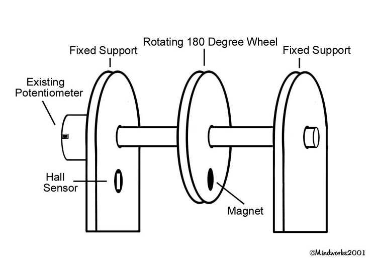
750 x 529 - 32K
Comments
I do not expect the Hall sensor will deliver a linear output change as your shaft is rotated using the mounting configuration shown. I think you may need to mechanically change the shaft rotation into a linear displacement of the magnet or sensor to improve the linearity of the output signal.
Also, the original pot produces its most extreme signals (either high or low) near the ends of the 180 degrees of travel. Since the lines of flux for your magnet are not drawn I am unsure if it is axially or diametrically magnetized. This will make a difference. If the magnet has poles that are aligned axially, its placement on the rotating wheel will result in central high signal level (or low depending on pole orientation) around the center position that then tapers back toward half the supply voltage regardless of direction. The direction of travel will be indistinguishable. If the magnet has poles that are diametrically aligned, its placement on the rotating wheel will result in a steeply changing region near the center of travel with signal levels that taper back toward half the supply voltage as the outer limits of rotation are reached. Basically, as soon as the physical edges of the magnet have passed the sensor the signal level will begin to return to the quiescent voltage. For this device, that is equal to about half of the supply voltage.
I do not think that either outcome is what you want. However, if you mechanically change the rotation of the shaft into a linear displacement of the sensor between opposite poles of two magnets and provide some means of adjusting the signal gain so it matches that of the original pot, then I think it just might work. At least the theory would then seem sound to me. Others may have more insight.
- Sparks
Thanks for the reply. I have attached a re-hashed drawing of my exsiting setup, minus the pot and with a flat magnet shown mounted flat against the side of the wheel. The position of the magnet centerline is aligned with the Hall sensor centerline, thus this should give me an output of 2.5 volts from the sensor if the supply voltage to the sensor is 5 volts. The volts rise gradually with the approach of the magnets south pole while the approach of the north pole gradually decreases the volts down to near zero. Would this be correct ? The flat magnet shown is for demonstration but round ones can be used if needed. Is a particular kind of magnet recommeded for use with the hall effect sensor or will any type of magnet·work ? In regard to the Hall sensor, it could be moved under the wheel for better linear results if needed. Is this what you meant by making the shaft linear ? In the drawing, I have the Hall sensor mounted to the fixed support bracket. I had planned on inserting a round magnet through the wheel towards the sensor. Is that an incorrect way of mounting it ? Sorry about all the questions but this is my first time working with Hall effect sensors. Is there more data, schematics or information on these great devices anywhere ?·I forgot to mention in my first post that the wheel must freely rotate to find earths center by means of a weight that is attached to the wheel. The stiff turning exsiting pot does not allow this to happen, hence the reason for wanting to use the Linear Hall effect sensor.
Twisted Pair....
Post Edited (Twisted Pair) : 11/16/2007 9:42:20 PM GMT
I need to dash off right now but I think I grasp what you are trying to do. You are making some kind of electro-mechanical stabilizer, right?
You may not need a directly linear response for that. By linear I mean that if you graphed the voltage output from the sensor against the position of the shaft the result would approximate a straight line as opposed to something with a distinct curve.
What I think you need to remember is that the magnetic force is going to be greatest on the furthest pole faces of the magnet. If you start with the center position of the shaft or wheel and the center of the magnet directly over the sensor, the effect from both poles will tend to cancel each other out leaving you with a mid level voltage. (You already have this clearly understood.) When one pole or the other is close enough to saturate the sensor you will see either a maximum or minimum voltage depending on which pole is very close to the sensor. (You understand this as well.) My expectation is that once a pole passes the sensor and continues to rotate further away from the sensor the output voltage will tend to return again toward half the supply voltage as the pole face of the magnet moves further way. If that happens it will then be hard to distinguish whether or not the wheel has rotated more toward the center or more toward the limit of travel in a certain direction.
I wish I could describe it better but I can’t with the time I have. However, if you were to use a bar magnet that was mounted through (or at least near) the center of the wheel, that should avoid the situation that concerns me most. (I tried to illustrate this by modifying your drawing slightly.) I think you want to devise a solution where either magnetic pole can rotate toward the sensor but neither one can rotate past the sensor. That is my main concern with my understanding of previous drawings.
- Sparks
You have hit the nail right on the head. That is exactly what I'm making. Sorry that I didn't know what to call it earlier. You have explained it well and I understood your tutorials. I took a voltage reading using the exsiting pot and here are the results. Center postion of the servo arm = 2.5 volts....Ninety degrees left = 1.0 volts....Ninety degrees right = 3.5 volts....I will experiment with the magnets placement to get the best saturation angles after I figure out which magnet is best to use. Do you have any recommendations regarding the type of magnets to use and where to get them? I had planned on using small round ones and just mount them through the wheel towards the sensor. On one side of the wheel centerline would be a North pole while on the other side a South pole with gap between them for the quiescent voltage. The smaller the magnet the better. Another point that I forgot to mention is that the wheel may stop at any point from zero to ninety degrees, left or right, depending on how much the bracket holding the wheel is tilted. Will the Linear Hall effect sensor saturation levels pick up these small variations or will the swings be large ? These variations will be as small as one to·five degrees of tilt at times....Will the Allegro A1301KUA-T work for what I want it to do ?
Thank You Sparks
Twisted Pair....
Post Edited (Twisted Pair) : 11/17/2007 12:17:23 AM GMT
Using two magnets might work as you describe and is probably worth exploring. It might be helpful for determining placement if you can somewhat visualize the magnetic lines of flux either mentally or with iron filings and paper. Unless you have a full comprehension of the mathematics for all the factors involved (I do not), you will likely need to try, test, adjust and retry until you get something that works for you. I think that what you are suggesting has enough merit to be worthy of exploration. I think there is a good chance this can be made to work!
I would not know how to determine that without a lot more data. If it is too much, use a less powerful magnet and/or move the sensor further away. If it is too little, use a more powerful magnet and/or move the sensor closer.
I can not say for sure. Based upon what I read and what I think you want to do, it seems like a good choice to me.
- Sparks
I know Radio Shack as rare earth magnets that are about 1/8" dia x 1/8" long. I used them for a pick-up for the speed sensor for my dirtbike. It worked great. At around $2, local, you could have one tonight.
http://www.radioshack.com/product/index.jsp?productId=2102642&cp=&sr=1&origkw=magnet&kw=magnet&parentPage=search
I think that is the link above to what I used. It says 3/16, but I recall it being smaller...
-Parsko
PS - Call to make sure they have it first... I called 2-3 stores before I found one that had them in stock.
Sparks, your help has proved invaluable and I look forward to hearing more from you regarding Linear Hall Effect Sensors. Parsko, thanks for the link to Radio Shack but I didn't buy any magnets from them because there were no Data sheets for the magnets that they sell. They might have worked but since my project is a precision device, I needed magnets with high flux and strength. As I continue forward with my project, I will update this post accordingly.
Twisted Pair....
Twisted Pair....
- Sparks
Twisted Pair....
I expect that a tradeoff exists between the magnitude of the signal level variations and the useable working distance of the sensors to a magnet.
- Sparks
Twisted Pair....
Twisted Pair....
▔▔▔▔▔▔▔▔▔▔▔▔▔▔▔▔▔▔▔▔▔▔▔▔
- Stephen
Thanks,
Twisted Pair....