Shop OBEX P1 Docs P2 Docs Learn Events
Connecting an AMP to a Propeller — Parallax Forums

Connecting an AMP to a Propeller

DgswanerDgswaner Posts: 795
edited 2007-11-17 07:03 in Propeller 1
I'm connecting a simple audio amp to my Propeller Proto board, this is a little different than a stamp, so I wanted to clarify a few things and not add more components than i need to.

here is the post about the amp
http://forums.parallax.com/showthread.php?p=688548

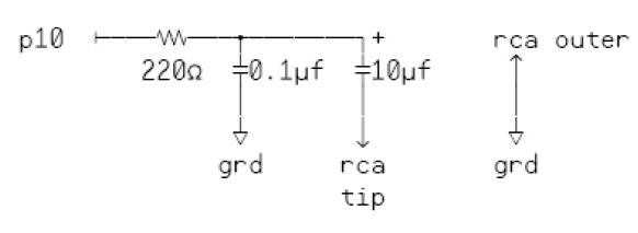
I looked at the Propeller cook book and it shows a simple circuit for connecting a RCA jack to the propeller for sound output. the circuit consists of a 22Ohm resistor a 0.1uF and 10uf cap. if I'm going straight into an amp do I need the caps? I'm guessing the resistor is there to limit current and the caps are for when the bass kicks it doesn't brown out.

if the circuit was designed to connect to and stereo (amp) I'd bet I Would need them with my amp.

Some insight would be helpful!

▔▔▔▔▔▔▔▔▔▔▔▔▔▔▔▔▔▔▔▔▔▔▔▔
A complex design is the sign of an inferior designer. - Jamie Hyneman, Myth Buster

Comments

  • Paul BakerPaul Baker Posts: 6,351
    edited 2007-11-15 18:31
    The resistor and cpacitor serve as the DAC, the Propeller drives it by PWM'ing the pin and the resistor and capacitor low pass filter the signal into an analog signal. You should keep the circuit and attach the output to the input of the amp

    ▔▔▔▔▔▔▔▔▔▔▔▔▔▔▔▔▔▔▔▔▔▔▔▔
    Paul Baker
    Propeller Applications Engineer

    Parallax, Inc.
  • DgswanerDgswaner Posts: 795
    edited 2007-11-15 18:36
    ahh, I see. Very important to keep them then. Ok I'm going to design them right into my amp circuit then. thanks for the quick response.

    Dave

    ▔▔▔▔▔▔▔▔▔▔▔▔▔▔▔▔▔▔▔▔▔▔▔▔
    A complex design is the sign of an inferior designer. - Jamie Hyneman, Myth Buster
  • Mike GreenMike Green Posts: 23,101
    edited 2007-11-15 18:42
    You need it all ...

    1) The Propeller switches its I/O pins quickly ... on the order of nanoseconds. The 0.1uF capacitor slows down these edges and smooths out the audio waveform

    2) The Propeller switches its I/O pins from roughly 0.3V to roughly 3.0V and back. By spending proportional amounts of time at 0.3V and 3.0V, the average voltage can be anywhere in between. The 0.1uF capacitor acts to store this average voltage and present it to the audio amplifier. Obviously, this average will vary at an audio rate to produce the waveform for the audio amplifier.

    3) The 10uF capacitor is to block any DC voltage while allowing AC to go to the amplifier. Because the Propeller output varies between 0.3V and 3.0V you effectively have a 3.0V - 0.3V = 2.7V peak to peak signal with a positive offset of 1.35V (1.35V - 2.7V to 1.35V + 2.7V). The 10uF capacitor blocks the DC component and the amplifier will just see the 2.7V peak to peak audio signal.
  • DgswanerDgswaner Posts: 795
    edited 2007-11-15 19:08
    If I have the circuit caps on my amp circuit board, connected to the propeller with 6-8" of wire is that going to cause a problem? sorry I do understand what your saying (barely) but I don't know enough to make my own conclusions.

    Thanks for explaining that, I'm learning a ton for this forum.

    DG

    ▔▔▔▔▔▔▔▔▔▔▔▔▔▔▔▔▔▔▔▔▔▔▔▔
    A complex design is the sign of an inferior designer. - Jamie Hyneman, Myth Buster

    Post Edited (Dgswaner) : 11/15/2007 7:13:55 PM GMT
  • Mike GreenMike Green Posts: 23,101
    edited 2007-11-15 19:17
    It would be better to have the resistor and 0.1uF capacitor close to the Propeller, then you could put the 10uF capacitor anywhere you want in the connection to the RCA jack or on the amp board. If you put the resistor and 0.1uF capacitor further away from the Propeller, the wire will radiate more high frequency electrical noise than it would if the resistor and capacitor were closer to the Propeller. In addition, it would be helpful to use a shielded audio cable for the 6-8" length, grounded at the jack ... not absolutely necessary, just good practice (and better sound).
  • DgswanerDgswaner Posts: 795
    edited 2007-11-15 19:41
    Ok I thought there might be something to it. I'll keep the parts you suggested local to the prop.

    thanks for the help on all of my little tangent projects.

    ▔▔▔▔▔▔▔▔▔▔▔▔▔▔▔▔▔▔▔▔▔▔▔▔
    A complex design is the sign of an inferior designer. - Jamie Hyneman, Myth Buster
  • DgswanerDgswaner Posts: 795
    edited 2007-11-16 15:07
    OK so I added the components on the protoboard, and for a while I couldn't get any sound. it was quite weird and maybe one day I'll understand what was actually going on. I finally got my first bit of sound when I touched the Pot. to adjust the volume I'm guessing I was acting as some sort of ground or antenna. as long as I was touching it I could hear sound. I messed with things and examined the Singing Seven code, and saw that it was outputting to 2 pins. so I said what the heck and attached it to two pins. This worked also but I didn't have any more caps, so it wasn't the best sound but it was working at that point. It was getting late so I didn't have much time to look at code and I don't know what the commands are so I'll just ask. Does sound on the propeller require 2 channels (2 i/o pins)? I'm not after stereo sound, and my amp circuit is a mono amp. if its a matter of rewriting a object every time someone comes up with something. I'd rather just use 2 channels. but if I use both channels I'm sure I can't just hook both I/o pins together and put them into the amp. I was thinking of a diode, but then I'm betting that would block the AC voltage to the amp. and lastly, when I fired this up it caused a lot of interfering on my daughters radio, about 5 feet away. Is this normal? I did have everything wire clipped together with long unshielded wires so I know that didn't help.

    Thanks again for the help.

    ▔▔▔▔▔▔▔▔▔▔▔▔▔▔▔▔▔▔▔▔▔▔▔▔
    A complex design is the sign of an inferior designer. - Jamie Hyneman, Myth Buster
  • RaymanRayman Posts: 14,162
    edited 2007-11-16 15:17
    What's the input impedance of your amp?· I got sound into a line-in port on my computer even without the blocking capacitor:
    http://www.rayslogic.com/propeller/Programming/dac/dac.htm
  • Mike GreenMike Green Posts: 23,101
    edited 2007-11-16 15:26
    Many of the sound programs are written for the stereo sound output of the Demo Board. On the other hand, the Hydra has a monaural sound output and some programs are written specifically for that. You can always use a program with stereo output and leave one I/O pin unconnected. If you want to have stereo output with a monaural amplifier, you'll need two sets of the resistor/capacitor network and connect the far ends of the 10uF capacitors together (where they would connect to the amp). You can't just connect the I/O pins together. It won't work and theoretically can damage the I/O pins ... from a practical standpoint, the I/O pin circuitry can handle the short circuit, but don't try this with other microprocessors.

    The switching frequency is high and, with long unshielded wires, you've got a radio transmitter.

    Rayman,
    Many amplifiers already have a DC blocking capacitor on their input, but some do not.
  • DgswanerDgswaner Posts: 795
    edited 2007-11-16 15:40
    I tried only having one pin connected and it didn't produce any sound. as soon as I connected the second pin, Sound! I think the best option is to tie the 2 outputs together, that way I won't have to mess with any new sound objects and have to convert it to mono sound.

    I don't know the Impedance of the AMP. I can connect it right to the I/o port of a BS1 or my computer and it works fine. and the propeller will work great if I get the caps on both channels.

    ▔▔▔▔▔▔▔▔▔▔▔▔▔▔▔▔▔▔▔▔▔▔▔▔
    A complex design is the sign of an inferior designer. - Jamie Hyneman, Myth Buster
  • Mike GreenMike Green Posts: 23,101
    edited 2007-11-16 15:50
    Do not connect the two I/O pins directly together! It causes an intermittent short circuit and stresses the I/O pin circuitry among other things.
    If you don't get sound without doing that, there must be something wrong with how you've wired it up.
  • DgswanerDgswaner Posts: 795
    edited 2007-11-16 16:18
    I connected them after the caps and resistor, and just a resistor on the one pin. for the final product I will connect them after the caps as you suggested.

    I'll have to double check the connection, the only time I get sound is with 2 pins connected.

    ▔▔▔▔▔▔▔▔▔▔▔▔▔▔▔▔▔▔▔▔▔▔▔▔
    A complex design is the sign of an inferior designer. - Jamie Hyneman, Myth Buster
  • DgswanerDgswaner Posts: 795
    edited 2007-11-17 07:03
    Success!!! OK after I fixed the entire circuit that was not even correct I now can hear "Singing Seven" loud and clear! each channel works separate now also. The crazy part was I had an open in part of the circuit and my guess is that it was acting like a radio xmitter so when I touched the pot is picked up enough signal to work. the fact that I didn't blow the whole proto board is a testament to how durable this board is. I'll try not to test the limits further.

    Thanks for everyones help.

    just to clarify, the circuit is correct I just didn't have it connected the right way.

    ▔▔▔▔▔▔▔▔▔▔▔▔▔▔▔▔▔▔▔▔▔▔▔▔
    A complex design is the sign of an inferior designer. - Jamie Hyneman, Myth Buster

    Post Edited (Dgswaner) : 11/19/2007 2:30:03 PM GMT
    640 x 480 - 98K
Sign In or Register to comment.