

PCB Design for 64 KEYPAD & 64 LED matrix Interface with Propeller
 DavidM
Posts: 640
DavidM
Posts: 640
HI,
I this is not "purely" propeller but the subject of keypad interfacing ( and LED driving) has come up a few times before,
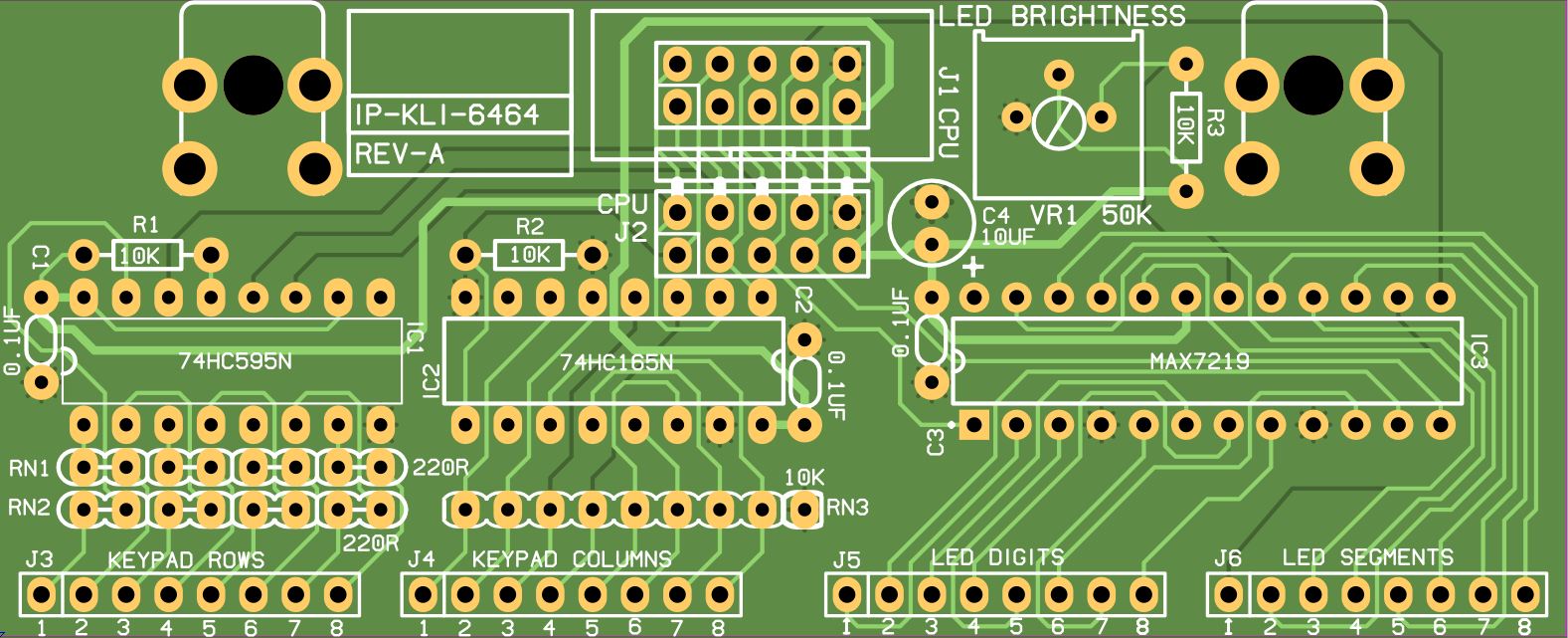
Further to my previous post about 64 KEYPAD MATRIX a few weeks ago, I have added 64 LED's outputs as well using a MAX7219, to a current PCB Design of mine.
This is designed as an INTERFACE to a KEYPAD MEMBRANE OVERLAY PANEL ( or similar) , Which has up to 64 buttons and 64 LED's. ( or less )
Its all designed using through-hole components so I can make them myself.
The board can be attached at right angles to the main propeller board ( my own prop pcb design that is!) using a 10 way R/A header or via a 10 IDC cable ( for testing ),
I found some nifty little solder-able right-angle brackets - http://www.keyelco.com/products/prod19a.asp?SubCategoryID=75
I am running both shift registers at 5 Volts, So I think I need some series resistors for the serial lines. ( I am running at 5V because I have only enough pins to run one power line through the header and the MAX7219 needs 5 volts.
What do you think? I figured that if you have many buttons in a device you may have many LED's as well!
I have not used the MAX7219, So I have designed "BLINDLY " with just the spec sheets, I have used a pot to allow the adjust of LED Brightness, or a fixed resistor can be used instead.
I will need some help later with the MAX7219 devices ( spin code that is) when I get my prototype boards made
I have some code for the shift registers, but need to make it do the MATRIX thingy? I dont think I will have too much trouble with that part.
This will be a lot easier as well when I finish my MEMBRANE OVERLAY PANEL DESIGN , but that is a few weeks away yet!
regards
Dave M
I this is not "purely" propeller but the subject of keypad interfacing ( and LED driving) has come up a few times before,
Further to my previous post about 64 KEYPAD MATRIX a few weeks ago, I have added 64 LED's outputs as well using a MAX7219, to a current PCB Design of mine.
This is designed as an INTERFACE to a KEYPAD MEMBRANE OVERLAY PANEL ( or similar) , Which has up to 64 buttons and 64 LED's. ( or less )
Its all designed using through-hole components so I can make them myself.
The board can be attached at right angles to the main propeller board ( my own prop pcb design that is!) using a 10 way R/A header or via a 10 IDC cable ( for testing ),
I found some nifty little solder-able right-angle brackets - http://www.keyelco.com/products/prod19a.asp?SubCategoryID=75
I am running both shift registers at 5 Volts, So I think I need some series resistors for the serial lines. ( I am running at 5V because I have only enough pins to run one power line through the header and the MAX7219 needs 5 volts.
What do you think? I figured that if you have many buttons in a device you may have many LED's as well!
I have not used the MAX7219, So I have designed "BLINDLY " with just the spec sheets, I have used a pot to allow the adjust of LED Brightness, or a fixed resistor can be used instead.
I will need some help later with the MAX7219 devices ( spin code that is) when I get my prototype boards made
I have some code for the shift registers, but need to make it do the MATRIX thingy? I dont think I will have too much trouble with that part.
This will be a lot easier as well when I finish my MEMBRANE OVERLAY PANEL DESIGN , but that is a few weeks away yet!
regards
Dave M
1577 x 641 - 216K
Comments
As to accessing it with spin code, as you have accessed shift register outputs before you should find it a piece of cake. Take CS low shift out the 8-bits of address (4 unused) and 8-bits of data then take CS high and the 7219 will do the rest. There are 8 addresses for the 8 digits of data plus other addresses to set some basic control functions.
If you don't use the internal decode mode (register 9) you will have to have your own segment decode table for the digits plus the characters if you are keen to read 7-segment characters. Your string and number output routines should also take into account the decimal point and set that independently from the 7-segments.
You shouldn't need to have a pot as the Iset resistor is only needed to set the maximum current after which you can control the intensity through register 0x0A.
BTW, your PCB looks nice, it's good to see you labeling connectors and pins where appropriate. Just hope it all works.
*Peter*
Thanks for the reply!
So , Only 5ma per segment!!,
"The MAX7219 is oldtech" , So what is the "NEWTECH" ??
I will remove the POT, as you suggested.
Thanks
Dave M